Author Archive
 Waiting for an AP510/AVRT5 APRS tracker
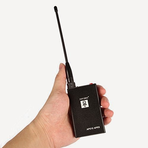
I just ordered an AP510/AVRT5 APRS tracker and am anxious to get my hands on it to try it out. I like the small size and the fact that it is self contained – no external wires are needed to have a fully functional tracker for the automatic packet reporting system APRS: But is it useful or just a toy?
The specifications from the Amazon.co.uk site are (adapted from Chinenglish):
- SainSonic AVRT5 APRS Tracker VHF with GPS/Bluetooth/Thermometer/TF Card, Support of APRSdroid
- GPS module: SIRF3 module, high sensitivity, fast positioning, stable power.
- GPS antenna: 18mm x 18mm active GPS antenna, built-in LNA amplification, Star Search, locate quickly.
- VHF Module (1W): The latest 1W VHF transceiver modules, small size, high stability for all types of wireless data transmission.
- VHF antennas are individually matched to transmitter to ensure that the standing wave ratio is proper and the emission is efficient.
I also signed up for the Yahoo group AP510 AVRT5 APRS.
 Congratulations to Logbook of the World
Congratulations to the ARRL Logbook of the World (LOTW) which just reached 100 million confirmed contacts. This is the same as an impressive 200 million QSL cards out of about 630 million uploaded contacts on LOTW.
LOTW was established way back in 2003. This was only 2 years after I got my license. Since I have never enjoyed much to fill in QSL cards I embraced LOTW very quickly. I have to say though that I will of course respond with a paper QSL for those who ask for one.
But LOTW has been my primary means of confirming contacts for a decade. My DXCC was confirmed with LOTW.
Now at the same time that LOTW is celebrating 100 millions confirmations, I am celebrating 8 bands with 100 or more contacts all confirmed via Logbook of the World. This is on all bands from 3.5 to 28 MHz. This has been my goal for many years. The last confirmation came from the TC0A contest station in Turkey on 80 m after last month’s CQ World Wide CW contest.
I consider myself lucky to have reached 100 confirmations even on the elusive 12 m band which we all know will shut down soon not reopen again until the next solar maximum in about 11 years time.
But as the saying goes “The journey is the reward“, so what to do next as a radio amateur?
 Milestone in blogging
Today the number of hits on my blog just exceeded a quarter of a million. When I converted my old web pages to a blog I didn’t really expect this many readers, so I thank you all for each and every hit on one of my 106 blog posts.
I have been blogging here since May 2011. But I have actually 23 posts which are older than that as I copied posts from my old web pages and gave them the original date of publication. The oldest post actually dates back to 2001 and is the first modification I published for my Elecraft K2. That was the year when I got my ham radio license
These are the most popular posts:
- How to make a very cheap VHF receiver (2011)
- The best of the Baofeng handhelds (2013)
- QRPp: Ultra low power operation with the Pixie (2011)
- Scratchy Tivoli Model One (2013)
- Temperature compensation for an Arduino ultrasonic distance sensor (2014)
- A regenerative receiver for the 40 m band (2011)
 So you want to play with a Pixie?
 |
| My own surface mount version of the Pixie2 |
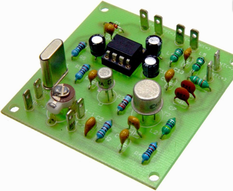
This page provides a guide to Pixie and related kits in a table format. These are simplistic single-band transceivers which are fun to build, yet they perform well enough to be used, although with some effort, for real contacts.
The idea of using the power amplifier transistor as a mixer seems to come from George Burt – GM3OXX – whose five transistor FOXX was described in 1983 in SPRAT. The basic design of the oscillator, PA/mixer and the simple keying has been more or less unchanged since RV3GM – Oleg Borodin – described the four transistor Micro-80 in 1992 in SPRAT. Later the Pixie 2 by WA6BOY replaced two of those transistors with the LM386 audio amplifier (QRPp 1995). Most later versions are variants of these designs.
Foxx | |
 Foxx-3 kit from Kanga, £29.95 | Incorporates a sidetone oscillator, changeover relay and low-pass filter. Different versions for the 80, 40, 30 or 20 m bands |
Micro-80 | |
 Kit from QRPme, $35.00 | Micro80D. Updated version with choice of high or low impedance headphone, polyvaricon tuning cap and board mounted connectors, 80 m. |
Pixie2 | |
 Kit from HSC Electronic Supply, $14.95 | For 80 and 40 m. Eham review |
 Kit from Kenneke, $29.95 | Includes 80 m crystal |
 Kit from QRPme, $40.00 | Lil Squall Transceiver ][. Several components and the output low pass filter are on sockets. Comes with a crystal for 40 m. |
 Ali Express Ham QRP DIY Kit Shack 40 m, $15.07 | 40 m version. Tuning pot for VXO. |
 Radi0kit, £22.00 | Enhanced Pixie2 which comes in 80, 40 and 20 m versions. Judging from the PCB layout it has an improved pin 7 muting circuit. |
What can we say to characterize these designs? One the one hand they are very simple to build and get to work. One the other hand they are also simple in the sense that they do not always perform very well. Therefore I don’t think I would recommend them to any novice ham. It takes some understanding of frequency offsets and sidebands in order to make real contacts. But many have had great fun with this minimalist transceiver which in its basic version puts out some 2-300 mW. And it encourages experimentation and modifications. Also, it should be remembered that it isn’t really necessary to get a kit, as the Pixie 2 is quite simple to build from scratch also. I did that myself.
The original designs and many variants and modifications are documented in the Pixie file document of SPRAT. There are many, many more clever modifications out there and I have my share on this blog also. To sort out and link to all the other pages is too daunting a task, so therefore I have focused on kits here. Finally I wouldn’t be surprised if the table is incomplete so I would appreciate comments if you think that something is missing.
 Digital Signal Processing
The Norwegian-language “The road to the international radio amateur license” came off the press this June. It is based on the RGSB International Amateur Radio Examination Manual from 2006, which RSGB graciously allowed us to use.
But the translation has been adapted on several topics. One example is the chapter on propagation due to the need in our country for more emphasis on propagation in polar regions and in mountainous terrain. Another is a completely new chapter on digital signal processing.
I got involved quite late in the project for this new chapter. The importance of digital signal processing in amateur radio has just kept on increasing as variable digital filters, adaptive noise reduction filters, adaptive notch filters, digital demodulation, and software defined receivers are everywhere.
The entire book project was handled by the Bergen group of the Assocation of Radio Amateurs in Norway. In fact it was done in order to celebrate their 90 year anniversary. The editor has been Frode Igland, LA6VQ.
My efforts resulted in a completely new chapter which was written during the first few months of this year. It was finalized with valuable input from the editor after a process of sending the manuscript back and forth lots of times. It was a fun project, where the challenge was to convey complex ideas with a minimum of equations.
The chapter has these headings:
- Applications of digital signal processing
- Discrete values
- Quantization – digitization of amplitude
- Sampling – digitization of time
- Aliasing
- Nyquist frequency
- Reconstruction filters
- The time domain
- The frequency domain
- The Fourier transform
- The Fast Fourier Transform (FFT)
- Digital Filters
- Moving average as an example of an FIR filter
- IIR filter equivalent of a low pass RC-filter
- IIR filter equivalent of a high pass CR-filter
- Example of a software defined receiver with spectral display

 New gadget measures negative resistance
If you are like me, you appreciate electronic gadgets with dials and displays. So when I discovered this “USB detector”, I thought to myself that I really always wanted to know the voltage as well as the current consumption of my USB devices. And since it is more or less impossible to connect a multimeter, this is exactly what I need.
The device fully satisfied my curiosity. Actually one surprising result was that the charger for my Samsung Galaxy Note 8 has a negative output resistance.
With a load it outputs 5.27 Volts as shown in the top image. Usually one expects the voltage to increase when the load is removed. But for this charger the voltage dropped instead to 5.13 Volts (second image). That should mean that there is the equivalent of a series resistance of (5.13-5.27)/0.98 which is about -0.14 Ohm.
I measured other chargers also, without finding a negative output resistance, so it seems as if it applies to this particular charger only. Out of curiosity, I also measured the current consumption of my Arduino Mega to 0.08 A without any shields connects.
The unit has two outputs which are different from each other. Output 1 is a fully functional USB port, while output 2 only connects DC power. What is that good for? Well, the epanoroma blog opened my eyes to the utility of this. If you charge your phone at some public place, then this feature isolates the data port of your phone. That may protect you from being hacked.
So there you see. The €5.13 were well spent and I even learnt something new by giving in to the temptation to click “Buy It Now” on Ebay.
But why does the Samsung charger have what amounts to a negative output resistance, is it by design or by accident?
 WSPR on 5 bands
For the first time ever I have been spotted on all the five bands that my Ultimate3 QRSS/WSPR kit (G0UPL design) is transmitting on. This is after 2-3 days of transmitting.
Right now I am using the beacon for discovering if the bands should open up on 24 and 28 MHz. The other three bands, and especially the 14 MHz band, serve as references to tell me that the transmitter is working. My antenna is not so optimal so I would be surprised if I am spotted far outside Europe. It is an end-fed 5 m long half wave vertical dipole which isn’t too bad for 28 and 25 MHz, and probably not very good at all on 21, 18, and 14 MHz.


