Author Archive
 Nice radio-related stamp
A few weeks ago I had one of my rare visits to the post office. As I was waiting, I saw a display of a new series of stamps and I just had to buy the one shown here. What caught my attention was not really the artist, but rather the Kurér portable radio.
The stamp was of course not about the radio but was issued in commemoration of the 100 year anniversary of the birth of Alf Prøysen. The English Wikipedia page has this to say about him:
Alf Prøysen (23 July 1914 – 23 November 1970), was a writer and musician from Norway. Prøysen was one of the most important Norwegian cultural personalities in the second half of the twentieth century, and he made significant contributions to literature, music, TV, and radio.
One of his main characters was “Teskjekjerringa” called Mrs. Pepperpot in English. She is shown here in the second stamp in the series. I remember this story very well from my own childhood in the 60’s as told in the characteristic calm and soothing voice of Prøysen himself. The character eventually appeared in 23 different languages. The radio is of course here because this and others of his plays were very popular on radio in the 50’s and 60’s.
And it was this radio, the Kurér (= Courier), that made me buy the stamp. It was a highly successful portable radio from the Radionette factory in Oslo from 1950 to 1958. It has four valves and covers long wave, medium wave, ‘ the trawler band’, and short wave. It has room for batteries (90 Volts and 1.5 Volts). But luckily it also has a built-in mains supply – the 90 Volt battery is hard to find these days. A total of 224 000 were produced and it was exported to many countries especially in the Middle East. It is very easy to repair even today.
I would think the most popular version today among collectors is the dark red one shown in the stamp. I have a grey one shown here with a simple medium wave transmitter that I have described before on top.
- Alf Prøysen honored with stamps
- Kurér radio. This radio could could need an English language Wikipedia page as well as a better Norwegian one.
- The Radionette factory 1927-1972
 Disappointment with Spice and the QRP-er’s favorite, the LM386
The trusty old LM386 audio amplifier from the 70’s is still used a lot in low power and portable equipment. Recently some ultra high gain circuits have been recommended that I wanted to simulate with Spice. I started with the datasheet examples for checking the quality of the model. The result was surprising.
In the data sheet one can find a minimum parts circuit, a high gain circuit, and a bass boost circuit:
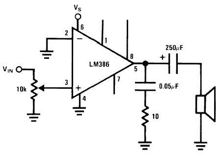 | 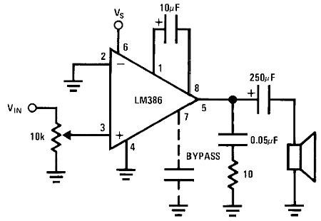 |  |
Gain = 20 (26 dB), minimum parts | Gain = 200 (46 dB) | Bass Boost |
There isn’t any official Spice model available from the manufacturer of the chip, at least not that I have been able to find. But there is a “no-frills LM386 model” attributed to Dave Dilatush (5/30/95) so I used that and a put it in a separate LM386.sub file.
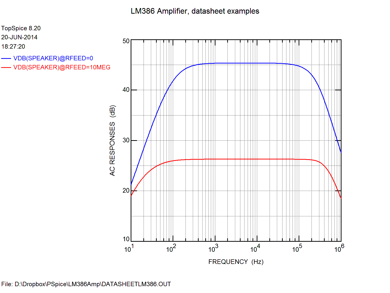
The Spice code is quite simple and listed at the end of this posting. The result is shown here in two sets of curves. The first is for the 26 dB and 46 dB amplifiers.
The first result is in the left-hand curve which shows that the high-gain version has problems with the low frequency response, so I increased the 10 μF feedback capacitor to 100 μF in the right-hand plot (between pins 1 and 8). That makes the plot almost as flat as that of the data sheet down to 100 Hz.
 |  |
| 26 and 46 dB amplifiers according to data sheet | 26 and 46 dB amplifiers with 100 uF in the feedback |
Second, the high frequency response is too high in the simulation compared to the data sheet shown below. The Spice model does not seem to have enough high-frequency roll-off.
Third, close inspection shows that the gain of the high-gain amplifier (the blue curve) levels off at 45.4 dB, not 46 dB. This should indicate that the open-loop gain of the Spice model is not high enough.
For comparison, the data sheet plots the responses as follows:
 | 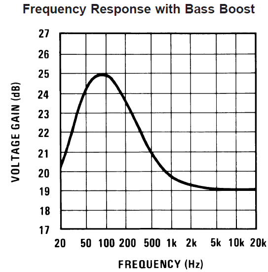 |
Finally here is the simulation of the bass boost. It is actually quite close to that of the data sheet, probably because the gain is not very high and the original plot only goes to 20 kHz.
In conclusion, in order to do simulate the LM386, there is a need for a Spice model with more roll-off at high frequencies and with a higher open loop gain.
I also observe that there is a constant current source in the LM386 model of value i1=5 mA. It must for sure be too high since the data sheet says that the quiescent current for the entire chip is min. 4 mA, max 8 mA.
Before there is any point in simulating the “Unleashing the LM386“-circuit that I introduced in Sprat (autumn 2003) or the simplified version that SM7UCZ (Johnny Apell) introduced in Sprat this spring – both based on the circuit of JF1OZL (Kazuhiro Sunamura), the Spice model needs some improvement. These circuits are also in George Dobbs, G3RJV’s articles in Practical Wireless, May and July 2014.
Actually I knew that improvements are needed since I have already tried with inconsistent results. But I have the hope that some of the readers may steer me towards an improved model.
Links:
- Dave Dilatush no-frills LM386 model.
- Comments on the quality of the LM386 Spice model.
- Datasheet for LM386
Spice code for use with TopSpice or LTSpice:
LM386 Amplifier
*
*
* LM386 Data Sheet curves simulated in TopSpice
* Sverre Holm (LA3ZA), 20 June 2014
*
**********************************
.include lm386.sub

* Step through 26, 34, 46 dB
cfeed nc4 100 10uF
*rfeed nc3 100 {Rvar};     LTSPice
*.STEP param Rvar LIST 0.01 10Meg;          LTSpice

rfeed nc3 100 10Meg;     TopSPice
.STEP Rfeed LIST 0 10Meg;    TopSpice

* Comment out for flat response (default)
*Xfeed nc3 output BassBoost

.probe
.ac dec 100 10 1e6 ; 100 steps per decade from 10 Hz to 1 MHz
*.tran 1u 3m 0 5u
.save vdB(speaker)
*.print ac V(speaker);  LTSpice
.print ac vdB(speaker); TopSPice

vsupply vcc 0 dc 9
rsupply vcc vs 10
csupply vs 0 470uF

vsignal inn 0 ac 1 sin 0 .05 1k
rplus nc1 0 1e-6

* Output circuitry
csnub output snub .05uf
rsnub snub 0 10
ccoupling output speaker 250uf
rspeaker speaker 0 32

xamp inn nc1 nc2 nc3 nc4 output vs 0 lm386

cbypass nc2 0 0.1uf ;bypass cap for PSRR

************************************************************
* Bass boost (in LM386 Data Sheet)
.subckt BassBoost nc3 output
cfeed output 10 33nF
rfeed nc3 10 10k
.ends BassBoost
************************************************************
.end
Spice circuit for the LM386 (store in LM386.sub):
* NO-FRILLS LM386 MODEL
* Dave Dilatush 5/30/95
*
*http://groups.google.com/group/sci.electronics/browse_thread/thread/4acbf7a7f3c36b0f/db8514b79b5b1709
*

* lm386 subcircuit model follows:

* IC pins:     2   3   7   1   8   5   6   4
*              |   |   |   |   |   |   |   |
.subckt lm386 inn inp byp  g1  g8 out  vs gnd

* input emitter-follower buffers:

q1 gnd inn 10011 ddpnp
r1 inn gnd 50k
q2 gnd inp 10012 ddpnp
r2 inp gnd 50k

* differential input stage, gain-setting
* resistors, and internal feedback resistor:

q3 10013 10011 10008 ddpnp
q4 10014 10012 g1 ddpnp
r3 vs byp 15k
r4 byp 10008 15k
r5 10008 g8 150
r6 g8 g1 1.35k
r7 g1 out 15k

* input stage current mirror:

q5 10013 10013 gnd ddnpn
q6 10014 10013 gnd ddnpn

* voltage gain stage & rolloff cap:

q7 10017 10014 gnd ddnpn ;
c1 10014 10017 15pf

* current mirror source for gain stage:

i1 10002 vs dc 5m
q8 10004 10002 vs ddpnp
q9 10002 10002 vs ddpnp ; diode

* Sziklai-connected push-pull output stage:

q10 10018 10017 out ddpnp
q11 10004 10004 10009 ddnpn 100 ; diode D1
q12 10009 10009 10017 ddnpn 100 ; diode D2
q13 vs 10004 out ddnpn 100
q14 out 10018 gnd ddnpn 100

* generic transistor models generated
* with MicroSim's PARTs utility, using
* default parameters except Bf:

.model ddnpn NPN(Is=10f Xti=3 Eg=1.11 Vaf=100
+ Bf=400 Ise=0 Ne=1.5 Ikf=0 Nk=.5 Xtb=1.5 Var=100
+ Br=1 Isc=0 Nc=2 Ikr=0 Rc=0 Cjc=0p Mjc=.3333 ;
+ Vjc=.75 Fc=.5 Cje=5p Mje=.3333 Vje=.75 Tr=10n ;
+ Tf=1n Itf=1 Xtf=0 Vtf=10) ;

.model ddpnp PNP(Is=10f Xti=3 Eg=1.11 Vaf=100
+ Bf=200 Ise=0 Ne=1.5 Ikf=0 Nk=.5 Xtb=1.5 Var=100
+ Br=1 Isc=0 Nc=2 Ikr=0 Rc=0 Cjc=0p Mjc=.3333 ;
+ Vjc=.75 Fc=.5 Cje=5p Mje=.3333 Vje=.75 Tr=10n ;
+ Tf=1n Itf=1 Xtf=0 Vtf=10) ;
.ends
*----------end of subcircuit model-----------
 Temperature compensation for an Arduino ultrasonic distance sensor
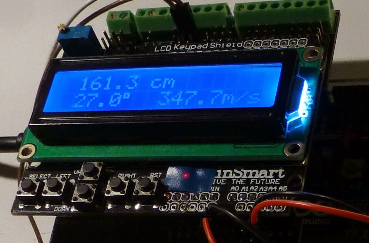 |
161.3 cm 27.0° 347.7 m/s |
Ultrasonic distance sensors can find the range out to 2-4 meters and are popular in e.g. robotics. Here I look at how the accuracy can be improved by compensating for the variation of speed of sound with temperature. It actually varies quite a lot in air and around 0 C it is:
c = 331.3 + 0.606 * T
where c is in m/s and T is in C. The formula is good to up to at least +/-30 C. There is also a dependence of humidity, but as it is so small it is neglected here.
The equation can be analyzed for sensitivity (a little bit of differentation, you know). The result is that a two-way range measurement creates an error of 1.8 mm/C/m. That means that with a 4 degree C error, the deviation will be 14.4 mm at a range of 2 meters. Not a lot, but more than the wavelength which is 9 mm at 40 kHz. Considering how easy it is to compensate for, then why not give it a try?
I have tested this with the inexpensive HC-SR04, but the compensation is really independent of the type of sensor. First let me analyze a typical example code for this sensor:
- For range in cm the code divides elapsed time in microseconds by 29. That corresponds to c=10,000/29=344.8 m/s. According to the equation above, this is the speed for a temperature of 22.3 C.
- For range in inches it divides elapsed time by 74. That corresponds to c=1,000,000/74 =13513.5 inches/sec =1126 feet/sec or 343.2 m/sec. This boils down to an assumed temperature of 19.6 C. That’s 2.7 degrees lower than the calculation for cm and means that the measurement in inches is lower than that in cm by 2.7*1.8 = 4.9 mm per meter of range.
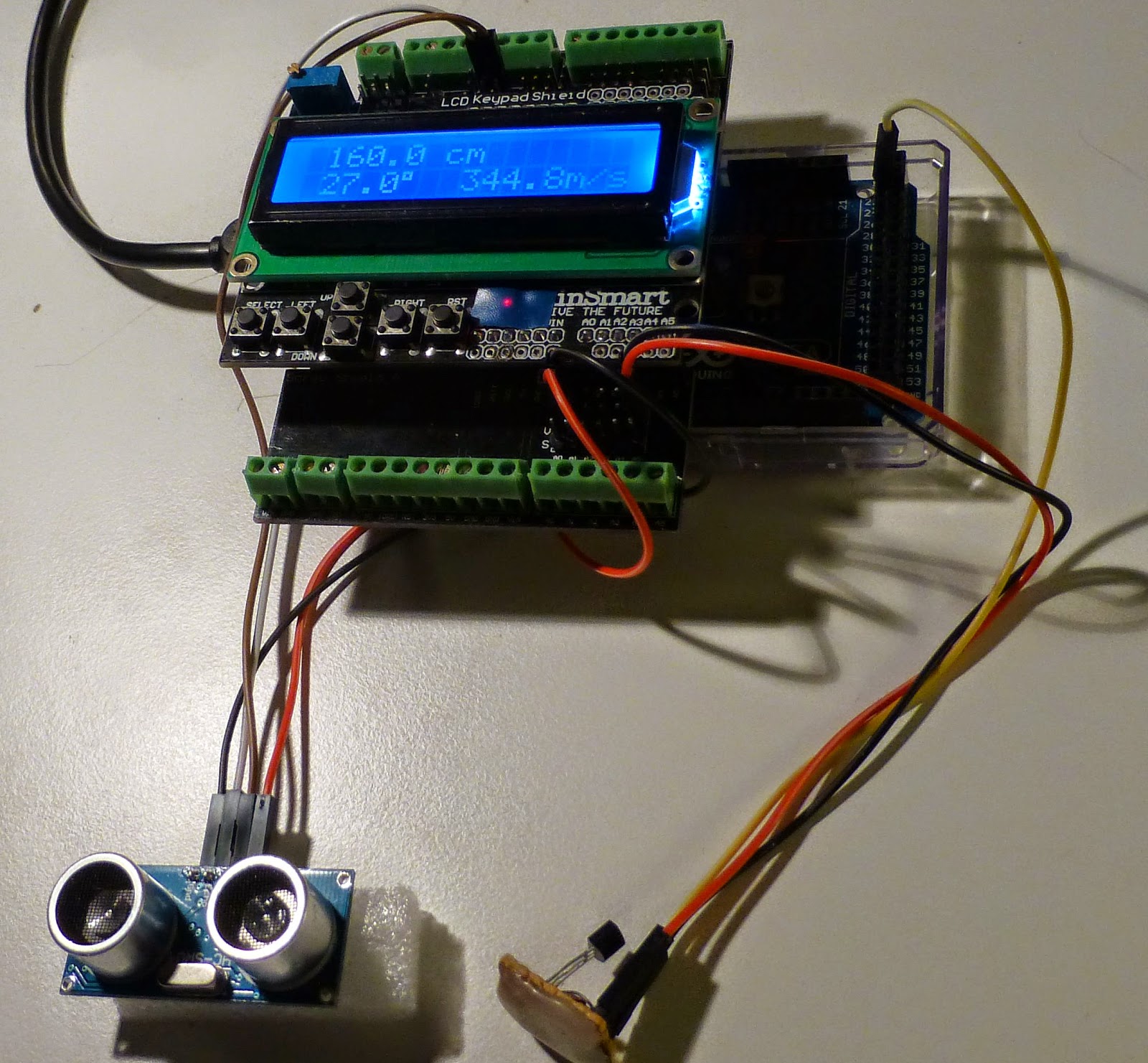 |
| Temperature is 27.0°, but the program doesn’t use that value and assumes instead its standard value of speed of sound of 344.8 m/s and finds 160.0 cm. |
I integrated an HC-SR04 program from Tautvidas Sipavičius with a code from the Arduino playground that uses the DS1820 1-wire temperature sensor (the last program on that page). In the process I had to convert the range estimation from integer to floating point arithmetic. This may give a speed penalty, but at least it runs fine on my Arduino Mega 2560.
The first image in this post shows that at a temperature of 27 C, the speed of sound is 347.7 m/s and the distance from my desk to the ceiling is found to be 161.3 cm. In the picture to the right, I have disabled the temperature compensation so the default velocity of 344.8 m/s is used instead and the estimated distance falls to 160.0 cm.
In the bottom picture, I have detached the 1-wire bus to the temperature sensor, so the program believes it is 0 C, and finds that the range drops to 154.5 cm.
 |
| 154.5 cm 0.0° 331.3 m/s |
Now, the HC-SR04 isn’t the most advanced of sensors. Other sensors may have a more accurate detection circuit that works more reliably and with better repeatability at longer ranges. I should also say that since I admitted a digit behind the decimal point in my code that wasn’t there in the original, my measurements wandered a bit from ping to ping also. In reality, I don’t think the HC-SR04 has much more accuracy than 1 cm. But it may have some potential for improvement as e.g shown here: “Making a better HC-SR04 Echo Locator“.
Combining a better detector with compensation for speed of sound variations with temperature should be what it takes to get the ultimate range sensor.
The Arduino sketch measures the range every 0.1 second and pauses for a second every 10 seconds to measure the temperature. The code is here (formatted with Hilite Me):
/* |
 Nice, watery CW signals from Alaska
 |
| Great circle path between Anchorage and Oslo |
Here’s what a transpolar signal sounds like (click here to listen) and looks like (below). This one has traveled from Anchorage, Alaska to Oslo, Norway.
The characteristic sound of a CW signal that has passed over a moderate geomagnetic disturbance (Kp = 2) isn’t too hard to recognize with a little practice. There is also some static on this short recording as we had a local thunderstorm coming in with the first summer days here.
The great circle distance between the two cities (actually their two airports) is 6446 km as illustrated by GPSVisualizer. Anchorage and Oslo are about at the same latitude, 61° N and 60° N, respectively. As they are at longitudes 149° W and 10° E, there is a difference of 159 ° – almost 180 ° – and this means that the signal almost passes directly over the North Pole, although a bit hard to see on the projection used in the map.
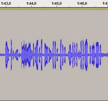 |
| “TU KL7SB UP“, 1550 UTC, 19 May 2014, 18 MHz |
There is rapid fading, or flutter, as seen e.g. from the large level difference between the two initial dots in “U”. Also the dah-dih-dah pattern of the “K” has more or less merged into each other in the image, but not in the audio, as this is caused by a static crash.
It was recorded just after my contact with KL7SB on 18 MHz today from my Elecraft K3 using Audacity® which is a free, open source, cross-platform software for recording and editing sounds.
 Practical Wireless with the LM386 unleashed
“Improving the LM386 Audio Amplifier” is the title of always inspiring Rev. George Dobbs G3RJV’s column in this month’s Practical Wireless. George talks about the basic amplifier with a voltage gain of 20 (26 dB) and how it is straight forward to increase gain to any value up to 200 (46 dB). The article then shows how it can be built dead-bug style.
Then he goes on to talk about various ways to improve the circuit such as for hiss reduction and even higher gain. In that connection he also mentions my article “Unleashing the LM386” from SPRAT in the Autumn of 2003. That circuit was an enhanced version of the high-gain circuit of Kazuhiro Sunamura JF1OZL. Basically it increases the gain to up to more than 70 dB, enough for it to drive a loudspeaker. My circuit also adds bandpass filtering. All this is achieved by adding only 5 passive components to the basic amplifier. The circuit was recently revisited in SPRAT by Johnny Appel SM7UCZ. He added a 40 dB Darlington pair preamplifier for even further gain.
The bandpass filtering (not low pass as the article says) is due to the series resonance of 100 uF and 1 mH which happens at about 500 Hz making it a nice CW filter.
It was good to see my article revisited as I think the idea deserves to be better known and to be considered in more LM386 amplifier circuits. The same goes for the improved muting circuit of the LM386 using pin 7. I developed both in the period when I was interested in minimal transceivers like the Pixie 2 and in true QRP spirit was interested in how to achieve much with as few as possible components.
One thing which is not mentioned in Practical Wireless is that the circuit may be used in such a way that it really squeezes out every grain of amplification of the poor little LM386, so the warning I wrote when I wrote an introduction to “Unleashing the LM386” for the blog (see link below) is worth repeating:
One word of warning is prudent here. As the 200 ohm pot approaches zero ohms, the amplification becomes so large that the series resistance of the 1 mH inductor and the ESR (equivalent series resistance) of the 100 uF capacitor in combination with the open loop gain of the LM386 will determine gain. Some of these values are unspecified for standard components and may vary a lot. Therefore such a setting is not recommended for use in mass-produced circuits. However for a hobbyist’s one-of-kind circuit it should be fine.
A poor copy of the last of the three pages of the Practical Wireless article, where the high gain options are discussed, is shown.
See also:
- Unleashing the LM386, introduction to article in SPRAT, No 116 (Autumn 2003)
- Using pin 7 of the LM386 to reduce BCI and add side tone to Pixie 2, based on article in SPRAT, No 113 (Winter 2002)
 Pulled out my dummy load tonight
 |
| Press image for a better view of the dummy load |
Testing a transmitter means the use of a dummy load. Trying to be considerate, I don’t want to cause unnecessary interference with my signals. So when I want to test my Ultimate 3 QRSS/WSPR kit I also pull out one of my dummy loads.
It measures just 9-10 mm across and is the size of a BNC connector. It is simply one of the many Ethernet terminations that I have lying around. Its built-in 50 ohm resistor is rated at something like 0.25 W. Considering that the kit outputs something like 200 mW that should mean that there is enough margin and no forced air cooling or liquid cooling is required.
These terminators were used with 10BASE2 or 10BASE5 ethernet. They are not so common anymore so the terminators are not that easy to find any longer. But they are still very handy for testing QRPP transmitters.
The size of these dummy loads should point out in a very vivid way how tiny the power levels of these transmitters are. Despite that, when running with the effective WSPR code, they can still be decoded on the other side of the globe.
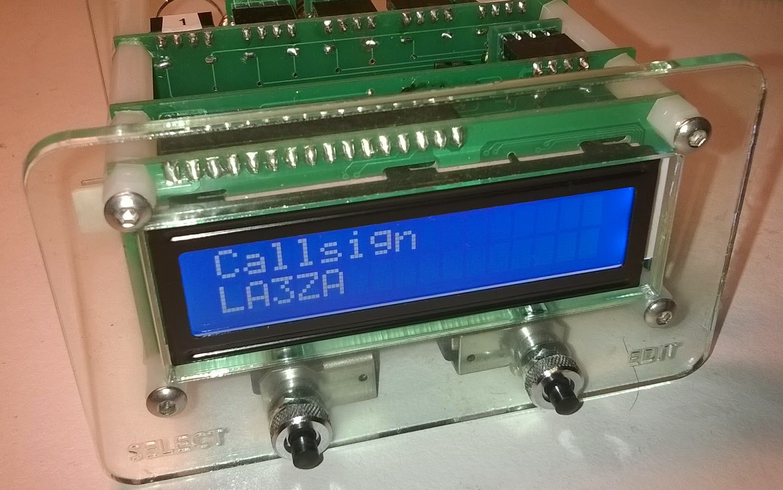
Showing just the back of a piece of equipment is contrary to my bragging instincts, so for completeness, the front of the Ultimate 3 QRSS/WSPR kit is also shown. It is housed in the minimalistic, but beatifully crafted acrylic enclosure from M0ION.
 Bletchley Park, Enigma, and GB3RS
 |
| Enigma (Photo: R. Holm) |
Bletchley Park, northwest of London (between Oxford and Cambridge), is one of the best known British sites from WW2. Its fame goes back to the breaking of the legendary Enigma cipher machine and its successor, the Lorenz cipher machine.
In order to perform this work a large effort in the development of early computers took place here. They include the mechanical Bombe for breaking the Enigma, and the valve-based Colossus for breaking the Lorenz.
The Bombe was reconstructed through a 13 year effort that resulted in an Engineering Heritage Award in 2009.
 |
| The Bombe machine (Photo: R. Holm) |
Colossus was the world’s first electronic digital computer that was at all programmable. It was also finally reconstructed in 2007 despite most of the hardware and blueprints being destroyed after WW2.
I visited it with my oldest son who lives in Cambridge, and it was a fascinating place that made me want to learn more about the work done at Bletchley Park and in particular one of the founders of computation, the brilliant Alan Turing, who was treated so badly after the war.
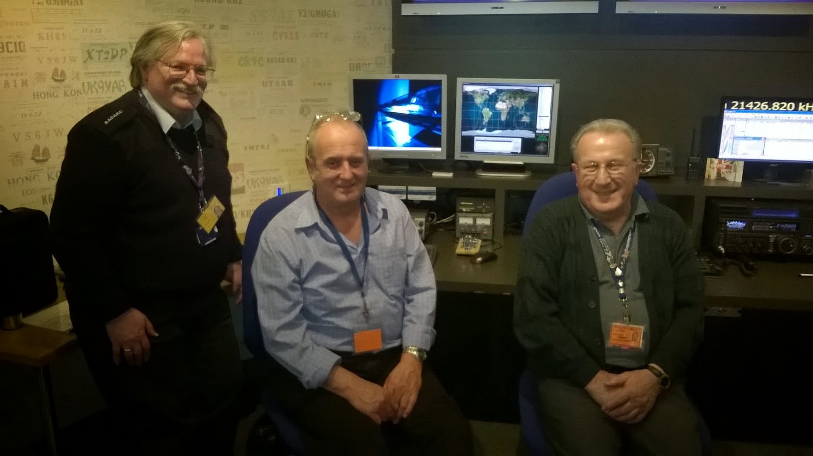 |
| From left: Henry Ehm (M0ZAE), Peter Davies (M0PJD), and Alan Goold (2E0GLD) on duty 5. April 2014 |
I was also impressed by the National Radio Centre run by the RSGB, callsign GB3RS, with its informative and well laid out exhibition and demonstrations.
They are able to keep it staffed for four days a week based on volunteers, and I really appreciated the hospitality and friendliness of the radio amateurs I met there.
If you ever come to London you should really try to visit this place. It is only a 36 minute train ride from London Euston station.


