Author Archive
 Single-lever and ultimatic adapter
 |
| Photo @LA3ZA |
Here’s an adapter that emulates both a single-lever paddle mode and the ultimatic mode. It is meant to go between a dual-lever paddle and an iambic keyer. The adapter has been implemented in an AVR Butterfly in C and it is compatible with Morse keyers such as the one in the Elecraft K3 and the K1EL WKUSB. The single-lever emulation is probably the most novel part and it is meant to make it easier to practice single-lever keying on a dual-lever paddle.
When pressing both paddles in the ultimatic mode the last one to be pressed takes control, rather than the alternating dit-dah or dah-dit of the iambic mode. The five possible states are then (from “An ultimatic adapter for iambic keyers“, Kevin E. Schmidt, W9CF, 2008):
- Lin = 1, Rin = 1 => Lout = 0, Rout = 0.
- Lin = 1, Rin = 0 => Lout = 0, Rout = 1.
- Lin = 0, Rin = 1 => Lout = 1, Rout = 0.
- Lin = 0, Rin = 0 after Lin = 1, Rin = 0 => Lout = 1, Rout = 0.
- Lin = 0, Rin = 0 after Lin = 0, Rin = 1 => Lout = 0, Rout = 1.
The left and right inputs are Lin and Rin and an open input is “1” and a closed one is “0” since the key grounds the input. The output is “1” when it is on and “0” when it is off. The adapter makes it possible with this mode on your favorite keyer where you may have missed this mode.
When I implemented the ultimatic adapter after W9CF’s instructions, it struck me that it would be both useful and easy to add an emulator for a single-lever paddle also. When both keys are pressed in this mode, the last one to be pressed is ignored. This gives the following inverted outputs in states 4 and 5:
- Lin = 0, Rin = 0 after Lin = 1, Rin = 0 => Lout = 0, Rout = 1.
- Lin = 0, Rin = 0 after Lin = 0, Rin = 1 => Lout = 1, Rout = 0.
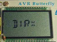
The code also has a direct mode that just sends the input unchanged to the output, as well as a possibility for exchanging the right and left paddles. The display may therefore show ‘ULT, ‘SGL, ‘DIR’ and ‘ULTx’, ‘SGLx’, ‘DIRx’ for these combinations.
The exchange mode is actually quite fun to use. In general for me it is easier to swap the paddles when keying with my left hand. I don’t think I am the only one with that experience.
The C code can be found below. These days I should probably have written it for the Arduino, but the code should be easy to move. Perhaps I’ll do that myself, now that I have an Arduino Mega on order.
Many keyers have the ultimatic mode and the possibility to exchange right and left, but no keyers have the single-paddle emulation mode as far as I know. I think it is quite useful. This summer when I implemented it I thought it was novel also.
But that was before I found out that this mode actually had been proposed by Larry Winslow, W0NFU, in QST in October 2009 and that one can get an iambic to single paddle kit from WB9KZY. Oh well, “there is nothing new under the sun” as the wise man of Ecclesiastes said some 3000 years ago. Just like the ultimatic mode has been implemented in many keyers these days, let me propose the single paddle mode for implementation as a new command also.
void paddle() |
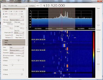
 Video of busy 70 cm ISM band due to car key fobs
Data recorded from an RTL-SDR USB dongle with the SDR# program using the Apowersoft Free Online Screen Recorder.
Related posts:
- “Car keys in the 70 cm band” (with more documentation of hardware and software)
- “Not so busy 70 cm ISM band”

 Not so busy 70 cm ISM band
Yesterday’s post entitled “Car keys in the 70 cm band” showed a very busy band around 433.92 MHz with up to 10 simultaneous transmissions. That snapshot was taken on a Sunday afternoon at 16:32 local time. Here is a much less crowded snapshot taken with the USB SDR-RTL dongle under the same conditions as the previous blog post. The difference is that this is from late Monday night at 23:34 local time:
 |
| Press image for a larger view |
Thanks to all viewers who have made the former blog post the most popular on my blog for this week. Thanks also to the RTL-SDR blog which gave it publicity in the blog post “Looking at the 432 to 438 MHz ISM band“.
Related posts:
 Car keys in the 70 cm band
 |
| Press image for a larger view |
Related posts:
- “Not so busy 70 cm ISM band” showing the status on a late Monday night
- “Video of busy 70 cm ISM band due to car key fobs“
 Clever K3 macro trick
Tonight I sat down to fiddle with the macros of my Elecraft K3. As I already use M1-M4 for CW memories, I only had the PF1 and PF2 buttons available.
It was the blog post “K-3 Rotating Macros” of W8TN that made me aware of a clever trick for using a macro to reprogram itself. This gives the possibility to have two rather than one function in the PF2 button. My need is for a button that can toggle between the typical pile-up functions Split+1 and Cleanup. In addition I have another macro that toggles speakers on and off.
The two first macros resemble those of W8TN, but are not quite the same:
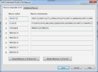
- Split+1: SWT13;SWT13;FT1;UPB4;RT0;XT0;SWT11;BW0045;SWT11; MN110;SWT12;SWH47;SWT14;
- 0 Split: FT0;RT0;XT0;LN0;SB0;SQ000;DV0;LK0; MN110;SWT11;SWH47;SWT14;
The Split macro in memory 1 means:
- SWT13; taps A>B once to copy VFO A frequency to VFO B
- SWT13; taps A>B again to copy all other settings to VFO B
- FT1; enters Split mode.
- UPB4; moves VFO B up according to setting 4, which is 1 kHz
- RT0; turns RIT off
- XT0; turns XIT off
- SWT11; taps A/B to go to VFO B
- BW0045; sets bandwidth B to 0.45 kHz
- SWT11; taps A/B to go to VFO A
- MN110; enters Config, Function, Macro
- SWT12; taps the (2) button to choose Macro 2
- SWH47; holds the PF2 button to assign it to PF2
- SWT14; taps the Menu button
Entries 10-13 are the reprogramming steps where the PF2 button is reassigned to the cleanup macro in memory slot 2. The contents of that macro is:
- FT0; turns Split off
- RT0; turns RIT off
- XT0; turns XIT off
- LN0; unlinks the VFOs
- SB0; turns subreceiver off
- SQ000; turns squelch off
- DV0; turns diversity mode off
- LK0; unlocks VFO A
- MN110; enters Config, Function, Macro
- SWT11; taps the (1) button to choose Macro 1
- SWH47; holds the PF2 button to assign it to PF2
- SWT14; taps the Menu button
 |
| Picture of Koss PortaPro from Wikipedia (Malcolm Tyrrell) |
Since I often toggle between speakers and my Koss PortaPro headphones (connected to the back of the K3), I liked what I just found on the Elecraft list where the command for speakers on/off was reposted. I have assigned that to the PF1 button which is also the RIT (Receiver Incremental Tuning) reminding me that this affects reception.
Macro 3 is MN097;UP;MN255; meaning:
- MN097; Access Menu, Speaker+phone
- UP; Change parameter
- MN255; Access Menu, Exit
After the macros have been loaded into the K3 with the K3 Utility Program, the macros are assigned to the PF1 and PF2 buttons by first entering Config, Macro 3, and then hold PF1, and then Config, Macro 1, and then hold PF2.
 Scratchy Tivoli Audio Model One
The Model One has been a huge success. But in many ways it is a daring retro design judging from all the features that are missing in this radio. I am thinking of features such as a customizable equalizer, a digital display, and memory presets. It just has a plain old analog tuning dial for FM and AM.
The radio could as far as I can tell just as well have been made in the 70’s except for some of the IC’s which are used. Actually it is easy to see the similarity with the even older KLH Model 18 from the 60’s, and yes – Henry Kloss played a role in both radio designs. But that makes for easy repairs, such as a seemingly common fault in the FM tuning capacitor, which over time may develop contact problems.
The radio is in many respects exceptionally well made. The tuning dial has a quality vernier drive. The audio section is well built with a powerful amplifier, a strong magnet for the loudspeaker, and a bass port design for the wooden cabinet. All are factors which contribute to its reputation for good audio. If one can trust measurements on the web, it has been equalized for enhanced bass and treble with the mid’s some 6 dB down. These are well-known tricks for getting a warm and crisp sound with universal appeal. Internally the tuner section, which is built around the TEA5711T chip, is well shielded for frequency stability as seen in image 2.
One weakness which manifested itself after only 3-4 years in this particular radio is that it became hard to tune, scratchy, and unstable on FM due to intermittent contacts in the tuning capacitor. According to the TEA5711T datasheet it is a varicon which for AM has 140/82 pF, for FM 2 x 20 pF, and for trimmers 4 x 8 pF. This particular unit had a Mitsumi varicon. Some say, when this fault occurs, that the varicon must be replaced and others say it can be cleaned. Who do you think I sided with?
Disassembling the radio is quite straightforward if you are used to this kind of work. The tuner is enclosed in shielding on both sides of the PCB. The shields can carefully be desoldered as shown in image 3. That exposes the varicon, and its plastic casing can be lifted as shown in the last image.
I sprayed it with contact spray and the radio came back to life. The only problem was that the tuning on FM had shifted so that a station on 100 MHz now appeared on 107 MHz. A little detective work around the circuit showed which trimmer that was for the FM oscillator and which one that was for the FM RF circuit (marked O and R in image 2). Since the oscillator trimmer was set for its maximum capacitance with the plates covering each other, it was easy to reduce the value and get the FM dial back to normal again, and then to peak the RF trimmer.
It got me wondering though to see that it had been necessary in the first place to have the oscillator trimmer set at its maximum value. It was just as if the tuning capacitor never had had its full value, even in the factory, and that it finally got it after my cleaning.
 The best of the Baofeng handhelds
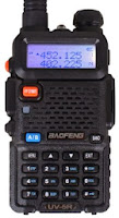
How do the cheap Baofeng handhelds compare? I have had the Baofeng UV-5R since I bought it from the 409shop in April 2012, but recently I noticed that the UV-B5, UV-B6, and UV-82 have appeared on the market also. If I should need another handheld transceiver for VHF/UHF, is there any advantage in getting any of the other models?
I prepared the following table in order to highlight differences and similarities. Bold characters signify an improvement for what I conceive to be typical radio amateur use.
Feature |  UV-5R |  UV-82 | UV-B5 |
|---|---|---|---|
| Front-end | OK | OK | Improved |
| Antenna | Short | Longer | Longer |
| Signal meter | On/off | On/off | Dynamic |
| Squelch | VHF: On/off UHF: Tiny steps 21. Dec 2013 | As the UV-5R 21. Dec 2013 | Larger steps |
| Size and shape | Square and small | Fits better in hand, larger buttons | Fits better in hand |
| Frequency/channel change | Up/down | Up/down | Rotary encoder |
| VFO/MR button | Yes | Turn radio off, then press menu as you turn it on 3. Jan 2014 | Yes |
| Band button | Yes | No (in menu) | Switches automatically |
| Dual PTT button | No | Yes | No |
| Programming | Need a computer to enter alpha tags | Alpha tags can be entered from keyboard | Alpha tags can be entered from keyboard |
| Memory channels | 128 | 128 | 99 + 16 for FM radio |
| Display | 7 characters in name | 7 characters in name | Harder to read, only 5 characters in name |
| Modifications | Enlarge mic hole, (and here), Low modulation mod | – | Unused button as background light switch |
My main sources are the blogs of PD0AC (UV-82, UV-B5/B6) and the Miklor FAQs
In general I think the design of much radio equipment is lagging behind other electronics when it comes to user interfaces. Imagine a smart phone user interface on a handheld! That is why I emphasize user interface issues in my final evaluation.
I like the improved front-end, signal meter, and squelch of the UV-B5 making it a strong contender for the winner position. But I don’t think they are worth the price of a poorer display. On the other hand, the UV-82 is inferior in my view to the UV-5R due to the need to enter the menu for VFO/MR and band switch functions. So for now I’ll stick with the UV-5R.


