Author Archive
 Elecraft K3 modifications
There aren’t that many modifications that you can do to the Elecraft K3. This is very different from the K2 as in my list I now have 138 different modifications for it. But Elecraft does have a few K3 enhancements and mods on their home page and here are two additional modifications that I have done to my K3.
 |
| Plug-in roofing filters on main RX board |
The first one is to add a wideband LC-filter (roofing filter). The filter was inspired by ideas from W5DHM with three tuned sections at the IF frequency of 8.215 kHz. It is to the right in the image. It is not the best of filters, and probably compromises performance somewhat, most likely because of its low image rejection 30 kHz away. It has however served me well as a receiver filter for the latest version of K1JT’s software WSJT-X. That software processes a 4 kHz band for both the JT65 and JT9 digital modes, and the LC-filter has demonstrated to me the utility of having a wide roofing filter for reception of those modes. The filter also works well for listening to broadcast AM which was what W5DHM designed it for in the first place.
 |
| Back panel of the K3 |
The second modification allows for a connection to the P3 Panadapter without using the recommended KXV3A Interface. All that is needed for the P3 is simply a minicoax with proper terminations. On the underside of the main PCB it should have a plug that connects to the J66 connector (see page 10 in the KXV3 manual). In the other end it is soldered to a BNC connector on the back of the K3. I put mine in the hole reserved for the REF input, as I don’t have the K3EXREF External Reference Input option. The BNC connector was marked with a label that says “IF out” as seen in the image.
Both of these modifications are temporary, and as a matter of fact the last one was just replaced by a KXV3A after several years of service. I needed the KXV3A for the PR6-10 preamplifier. I also plan some day to replace the wideband LC-filter with either the KFL3A-6K 6 kHz AM/ESSB filter or the KFL3B-FM 13 kHz FM filter.
 Studies on Morse code recognition
 |
| Nice drawing of Morse key by Dutch radio amateur Dick Kraayveld, PA3ALM (http://www.morsecode.nl/pa3alm.html) |
In the early 90’s there were some interesting studies performed on Morse code recognition and the effects of pitch frequency, signal to noise ratio and code speed. They were part of the PhD work of Peter Montnémery who is a medical doctor and also radio amateur SM7CMY. I reread these papers now since there was a discussion on the pitch frequency (CW pitch resolution) just recently on the Elecraft mailing list. This discussion comes up from time to time, as it did for instance in 2006 also (Sidetone questions — copy speed vs sidetone pitch).
The two first papers are probably the most interesting ones for radio amateurs, so therefore I have posted their abstracts and a key figure from each of them also.
 |
| Press figure for larger size |
Paper 1: Montnemery, P., Almqvist, B., & Harris, S. (1991). Recognition of Telegraphy Disturbed by Noise at Different S/N-Ratios and Different Telegraphy Speeds A Comparison to Short-Tone Audiometry. Scandinavian Audiology, 20(1), 33-39.
Abstract: “The ability to recognize telegraphy at different S/N ratios and telegraphy speeds was compared for 10 normal-hearing men trained in detecting telegraphy. The ability to recognize telegraphy disturbed by noise decreased with increasing telegraphy speed and reduced S/N ratio. The recognition of telegraphy disturbed by noise seems to follow the relations known from experiments with short-tone audiometry.”
The figure above (Fig. 5) shows recognition in % vs signal to noise ratio (SNR) for speeds 13, 25, 40, 63, 82, and 103 characters per minute (CPM) which when divided by five correspond to 2.6, 5, 8, 12.6, 16.4, and 20.6 words per minute (WPM). Note how recognition at the 90 % rate is easiest (works under lowest SNR) at 5 WPM, then 8, then the exception for the slow speed 2.6 WPM, and then gets even harder at speeds 12.6, 16.4, and 20.6 WPM.
 |
| Press figure for larger size |
Paper 2: Montnemery, P., Almqvist, B., & Harris, S. (1992). Recognition of telegraphy signs at different listening levels and frequencies. Scandinavian Audiology, 21(4), 255-260.
Abstract: “The recognition of telegraphy masked by noise at 40 and 80 signs/min telegraphy speed was studied in 10 normal-hearing subjects at different sound pressure levels (25–85 dB SPL in steps of 5 dB) as well as at different test frequencies (2000, 1000, 800, 630, 500 and 250 Hz). The ability to recognize the signs varied with varying SPL. Recognition for most of the subjects was best at an SPL close to 70 dB. All subjects improved their recognition as the frequency was lowered to 500 Hz, some even at 250 Hz. These facts should be taken into consideration when training telegraphy operators as well as in the construction of radio receivers to permit listening at low frequencies. Furthermore, the critical ratio was calculated at the different test frequencies.”
The figure above (Fig. 6) shows recognition rate at different pitch frequencies at a speed of 80 CPM = 16 WPM. There is an improvement as the pitch is lowered and it more or less seems to level off at 500 Hz, except for the lowest SNRs (-13 and -14 dB) which improve at a pitch of 250 Hz. As a side note, the SNR scale must be different from that in the former figure since the values are considerably lower here.
The other papers in the thesis “Signal Detection in Noise, with special reference to telegraphy” are:
- Paper 3: This study is on the effect of stimulating each ear simultaneously with different sounds: Montnemery, P., & Harris, S. (1995). Effect of dichotic presentation on the recognition of telegraphy signs. Scandinavian Audiology, 24(1), 39-45.
- Paper 4: Montnemery, P., Almqvist, B., & Harris, S. (1995). Performance of electronic Morse decoders in decoding telegraphy masked by noise. Scandinavian Audiology, 24(1), 57-62.
- Paper 5: Montnemery, P., & Harris, S. (1995). Recognition of telegraphy in hearing-impaired telegraph operators. Scandinavian Audiology, 24(2), 107-115.
The first paper shows how lowering the speed enhances recognition when conditions are poor. Unfortunately only 250 and 500 Hz were tested in the second paper, but it should be clear that a low tone is preferable. If one were to do a follow up study, it would be interesting to zoom in on the frequencies between 250 and 500 Hz for further testing. Since 40 and 80 CPM is only 8 and 16 WPM, it would also be interesting to test at higher speeds.
 The simplest possible AM transmitter
Here’s a design for a 1 MHz amplitude modulated (AM) transmitter. I’ve been looking a while for something like this, a simple short range AM transmitter for the medium wave band, as I needed something for demonstration of my collection of old radios.
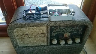
The result is the AM transmitter shown here in an Altoids tin on top of a Radionette Kurér radio. This is a portable tube radio from the 1950’s. Several hundred thousands were produced, and it was exported from Norway to 60 countries. It is still popular among collectors.
The transmitter is as simple as it gets. The heart of it is a 1 MHz crystal oscillator in a can. Its 5 Volt power is modulated via an audio transformer, one taken from the output of a transistor amplifier (primary 147 ohms – secondary 3 ohms). I drive the modulator from my cell phone into the low resistance side of the transformer and get good audio when the phone’s volume is set to maximum.
The design was inspired by one from Instructables, but mine also has a 78L05 5 Volt voltage regulator and a red LED in series with the power supply. It indicates that the battery is plugged in. In total the transmitter draws 4.4 mA at 9 Volts. The input power to the oscillator is less than 5 Volts * 4.4 mA or in the order of 20 mW. The power output is just a fraction of that. I have tested it with a 1.5 m wire hanging down behind the built-in frame antenna in the back of the radio with good results.
This is really just a modulated marker transmitter as I have briefly described on this blog before, and the square wave will have harmonics of 1 MHz over the entire short wave band. Some of these frequencies may propagate really well, so if used with a longer antenna, it should really have an output low pass filter to prevent that.
I’m not totally happy with this design, despite its simplicity, though. If I could, I would rather like to transmit in the long wave band at 216 kHz. This is the old frequency of the Oslo transmitter which ceased operation in 1995. As a member of the Norwegian Radio Historical Society, I am allowed to use that frequency with a transmitter input of 0.5 W for demonstration purposes.
For other frequencies, one simple alternative is a standard canned oscillator at 1.288 MHz. I also believe some of the Silicon Labs oscillators can be used in order to get an adjustable frequency, but I haven’t tried that myself.
But until I find a suitable frequency source at 216 kHz, I’ll stay with the 1 MHz alternative at a mere 20 mW. It is in line with the best principles of KISS (keep it simple stupid) or with Occam’s principle : “It is vain to do with more what can be done with less“, i.e. the QRP philosophy.
 Q codes from the streets of Paris
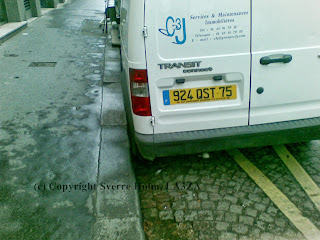
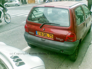
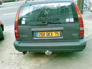
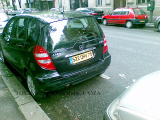
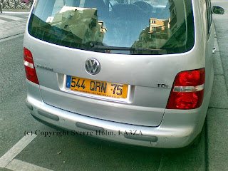
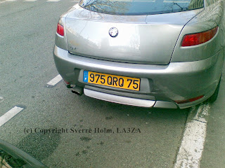
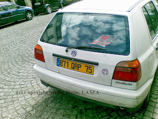
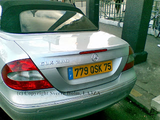
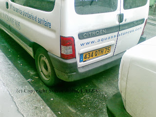
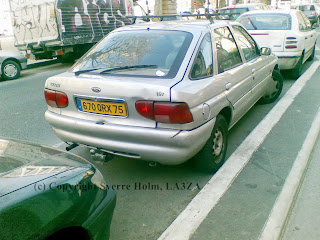
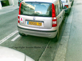
I had the privilege of living in Paris with my wife a few years ago. At that time, 2008/2009, the series for car license plates had just come to Q. That made it easy to find plates with many of the Q codes which are used as abbreviations in radio communications. What follows is the result of walking the streets of Paris, mostly between the 5. and the 13. arrondissement:
Here is a broadcast to all radio amateurs:
Watermarking by http://www.watermark-images.com/
 What’s in a name – radio societies all over the world

Image © Freeworldmaps.net
The IARU HF Championship took place this weekend. This is the contest where every country has national stations which exchange the abbreviation of the radio amateur society. Therefore it was an opportunity to reflect on what the names of the national societies mean. Many of the names in the IARU list portray the heritage of a hundred years. It is not so strange then that this may make some of them hard to understand and even a bit old-fashioned.
Starting with the ARRL – American Radio Relay League or NRRL (Norwegian …) then this is about a network of stations relaying messages in a country with large distances. This is a bit 1920’s to me. Looking at the ARRL web page it looks as if the the ARRL agrees and really would like to modernize the name to the National Association for Amateur Radio. The Portuguese may already have modernized it a bit by the use of network instead of relay: “Rede dos Emissores Portugueses” (Network of Portuguese Transmitters), or perhaps it is just because this is the same word as “relay” in Portuguese?
Most societies have “radio amateur” in the name like the German and the French: Deutscher Amateur Radio Club, Union Francaise des Radioamateurs. My knowledge of Spanish is not so good but this one sounds better to me: Union de Radioaficionados Espanoles as “radioaficionados” gives me the impression of “radio fans”, but perhaps it is just another word for “radio amateurs”?
Just like “radio relay” is a bit old-fashioned, the Swiss also have an old name in Union Schweizerischer Kurzwellen-Amateure. It must have been coined before VHF and UHF as Kurzwelle means Shortwave.
A name which sounds more contemporary despite its age is the Radio Society of Great Britain. Many others have similar names, one example is Amateur Radio Society of India.
The word “club” is used by many and seems to emphasize the hobby aspects, e.g. Radio Club Argentino and Český radioklub (Czech Radio Club).
Contesting is in many ways like a sport, at least in the same sense as chess is called a sport today. Examples that use this word are Chinese Radio Sports Association, Belarussian Federation of Radioamateurs and Radiosportsmen, and Mongolian Radio Sports Federation.
The there’s those who value the experimental aspects, like Vereniging voor Experimenteel Radio Onderzoek in Nederland (Society for Experimental Radio Research), Experimenterende Danske Radioamatører (literary Experimenting Danish Radio Amateurs) and Federacion Mexicana de Radio Experimentadores.
A similar technical emphasis is in the word “transmitter”: Irish Radio Transmitters Society, Foreningen Sveriges Sändareamatörer (literary Society of Swedish Transmitter Amateurs) and Österreichischer Versuchssenderverband (literary Austrian Experimental Transmitter Society).
The protection from the royal family exalts the society, but it is something I could only find in Belgium: Royal Union Royale Belge des Amateurs-Emetteurs / Koninklijke Unie van de Belgische Zendamateurs / Königliche Union der Belgischen Funkamateure.
Finally, these are the most serious and ambitious names I could find: Egyptian Radio Amateurs Society for Development, Syrian Scientific Technical Amateur Radio Society, and above all the Wireless Institute of Australia.
Which words should be used in the name of a radio society today? It’s a balance between reflecting a hundred years of history and communicating with contemporary people.
Personally I don’t like to use the word “amateur”. It comes originally from the same root as “amour” and “amore” and thus means someone who loves and is passionate about something. But today it gives the impression of being unprofessional. A contemporary name should also emphasize the experimental side in my view.
 The radio amateurs are coming! Oslo Mini Maker Faire
“Have you dreamt about sending radio signals via the ionosphere? Or what about studying moon bounced echoes? Visit the radio amateurs and you can learn about analog and digital radio communications, antennas and electronics. There are 5-6000 radio amateurs in Norway, and they probably represent the oldest maker hobby.”
This was the enthusiastic introduction that we were given on the web pages of Oslo Mini Maker Faire. It was arranged at Norwegian Museum of Science and Technology on April 6-7, 2013 in collaboration with the University of Oslo. There were close to 4000 visitors during the weekend and about 100 exhibitors. Our joint stand between the radio amateurs of the Asker/Bærum and Oslo clubs also had a constant stream of visitors.
 |
| LA3ZA, LA5FRA, LA9UTA and LA8OKA at the stand (photo LA5FRA) |
Our stand was only active on the first day, and it was manned by LA8OKA Martin, LA5FRA Paul Henrik, and LA9UTA Erlend in addition to me who served as the liaison to Oslo Mini Maker Faire since my employer, the Department of Informatics at the University of Oslo was a sponsor of the Faire. There was also a good deal of curious radio amateurs that stopped by during the day.
We had a couple of Elecraft K2’s, several home-brewed electronics projects, the possibility to send your own name in Morse code, and several posters that covered everything from emergency communications and APRS to radio amateurs on the space station.
 |
| LA8OKA explaining the innards of the K2 |
We also had a 0.15 W WSPR transmitter that we had hoped could transmit out through one of the large windows. The intention was that we could follow its reports on the internet, but there turned out to be too much metal in the window frames and the curtains so radio waves would neither enter nor exit – whether it was HF, VHF, or GPS-frequencies. Therefore we ended up explain the fascinating aspects of radio propagation from posters instead.
There was much interest in our stand, and many expressed that they found ham radio to be exciting. Several were also interested in ham radio courses. Among pan cake robots and other robots, 3D printers, Star Wars-enthusiast, computer gamers, 3D photo, advanced Lego builders and Norway’s largest smoke ring canon, this was finally a place where people like us with as nerdy an interest as radio felt quite normal.
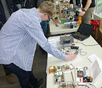 |
| Trying out Morse, in the background a 3D printer |
This was therefore a perfect place for radio amateurs to take part and since it most likely will be arranged again we should be prepared to take part next year also.
 Young operators in All Asian contest
The All Asian DX Contest is one of the more fun ones to participate in. One thing is the DX aspect of it, but I like it also because of the exchange of the age of the operators. In other contests one exchanges boring stuff like serial number 1, 2, 3, … ; the CQ or IARU zone (14 and 18 for me); or the power output. But exchanging the age of the operators gives a little glimpse of the person behind the radio on the other side.
It also makes it possible to make a graph of the distribution of age. I had 62 contacts this weekend, of which 55 were unique. They were mainly in Asiatic Russia and Japan. The average age of the operators was 51.6 years – 7 years younger than me – and the graph shows the distribution. The bar for e.g. 54 is the percentage, 20 in this case, of operators in the bracket 50-54 years and so on.
The graph actually makes me quite optimistic concerning the future of ham radio. There are many young contest operators out there, at least in Asia. This resonates well with what others are saying also. Never before has there been so large activity on the bands as during contests these days.
