Author Archive
 GSM phone power control and signalling
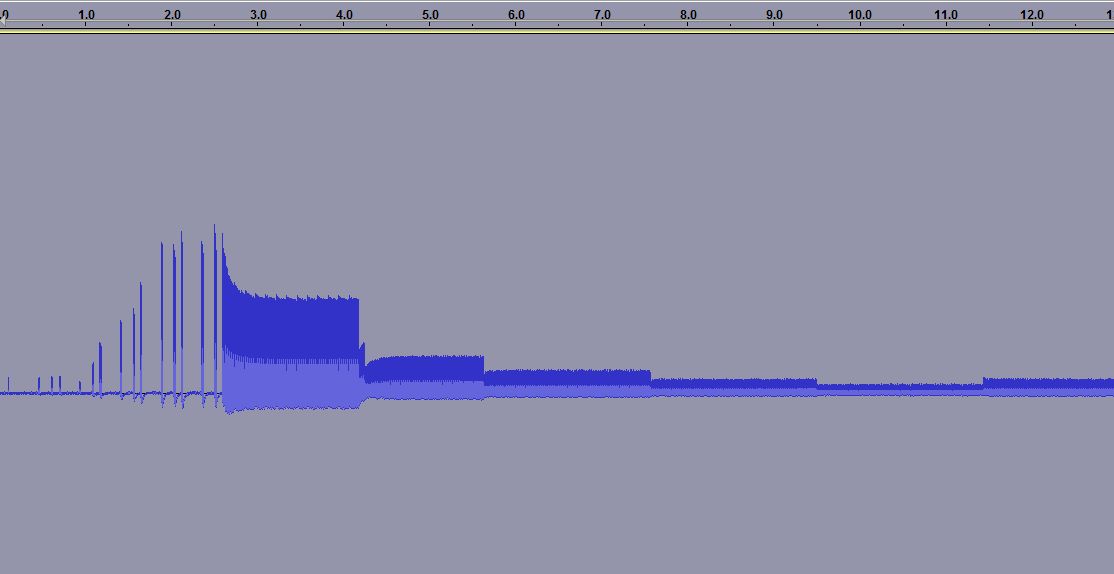
When you measure the energy out of a GSM cell phone at the moment of initiating a call, you get the picture to the right. It shows the first 15 seconds.
For the first 3.5 seconds there is the signalling between the phone and the base station. Then the connection is established, but after some time (at 4.2, 5.6, 7.5 and 9.5 seconds) one can see how the phone turns the power down, according to the commands it gets from the base station.
 The first example was for the case of a strong received signal, all bars are shown in the signal strength meter. The reduction in power, preservers battery life and as a side effect the user is exposed to a smaller amount of radiation. Interestingly, one can see that after a while there is a small adjustment of the power and it is turned up a bit (at 11.5 seconds).
 In other cases one can see a situation which follows the same pattern in time, except that the power stays at a high value. This second recording was done in my basement where GSM coverage is much poorer. Here the phone’s signal level indicator hardly shows any signal.
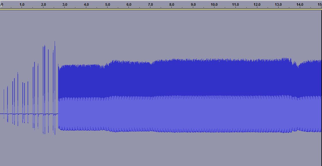

The third plot is a zoom of the previous one. Here one can see how the phone only transmits 1/8 of the time as it shares the channel with 7 other phones in a time multiplex. It is allowed to transmit every 4.6 ms and this is the reason why one often can hear a buzzing sound at 1/4.6 ms = 217 Hz in equipment which is placed close to a phone.
One also sees another frame structure, as the phone transmits 25 bursts and then breaks for one burst before continuing. Every transmission consists of 150 bits, but that is not possible to resolve with the simple setup that was used here.
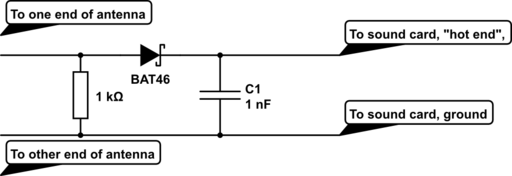
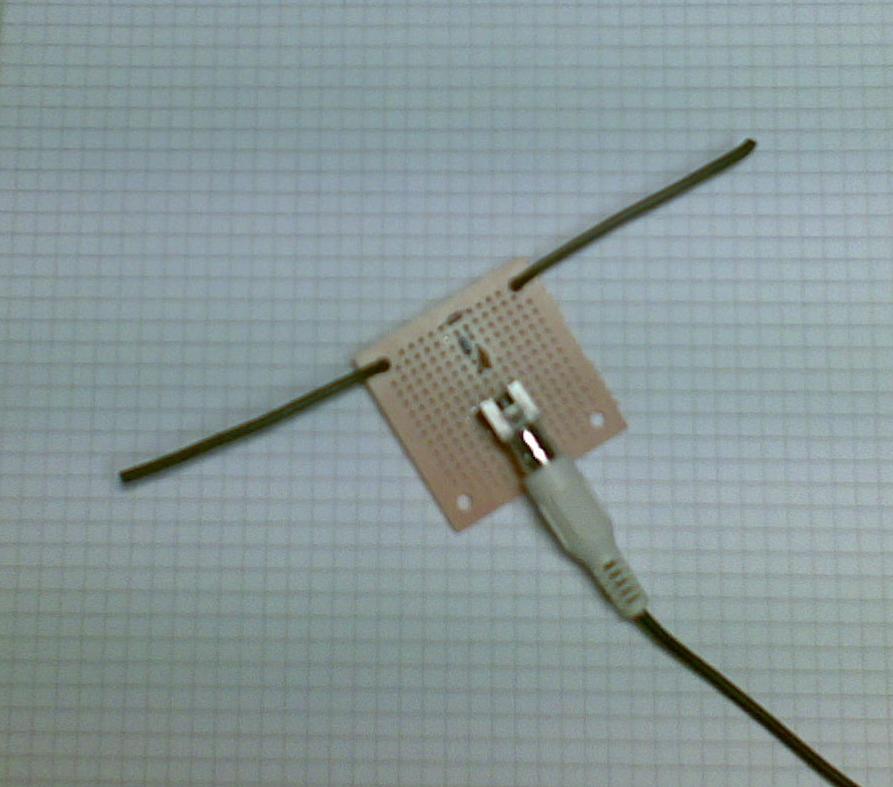 The equipment was a dipole antenna and a simple diode detector:
- A half wave dipole antenna for 950 MHz has a length of 0.5*3*108/950*106 = 15.8 cm, thus the antenna is about 2 x 8 cm (probably not very critical). The antenna was made from stiff self-supported wires.
- There is a resistor of R=1 kohm across the antenna and then a Shottky diode which acts as a detector (A Shottky diode which handles higher than 1 GHz is needed and BAT46 was used here), and finally a 1000 pF capacitor as a filter.
This post was inspired by William Andrew Steer’s “GSM phone signal analysis“.
Half a year of APRS temperature monitoring
 My APRS-based temperature monitor has now worked flawlessly for half a year. APRS stands for Automatic Packet Reporting System so it can send much more than temperature data, the chief usage is really for GPS position reports.
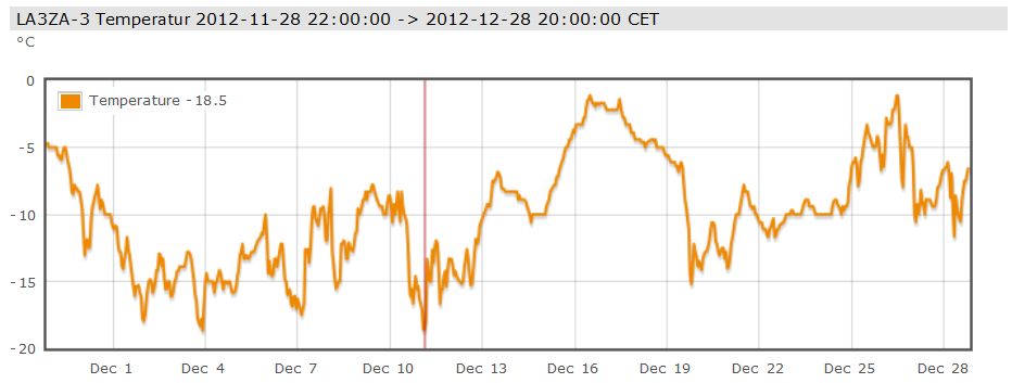
But I just needed a temperature monitor and here are the readings for December. As one can see, there were no days with temperature above freezing. At 800 m elevation in the mountains of Telemark in Norway, this is not unexpected for this time of year and makes for good skiing!
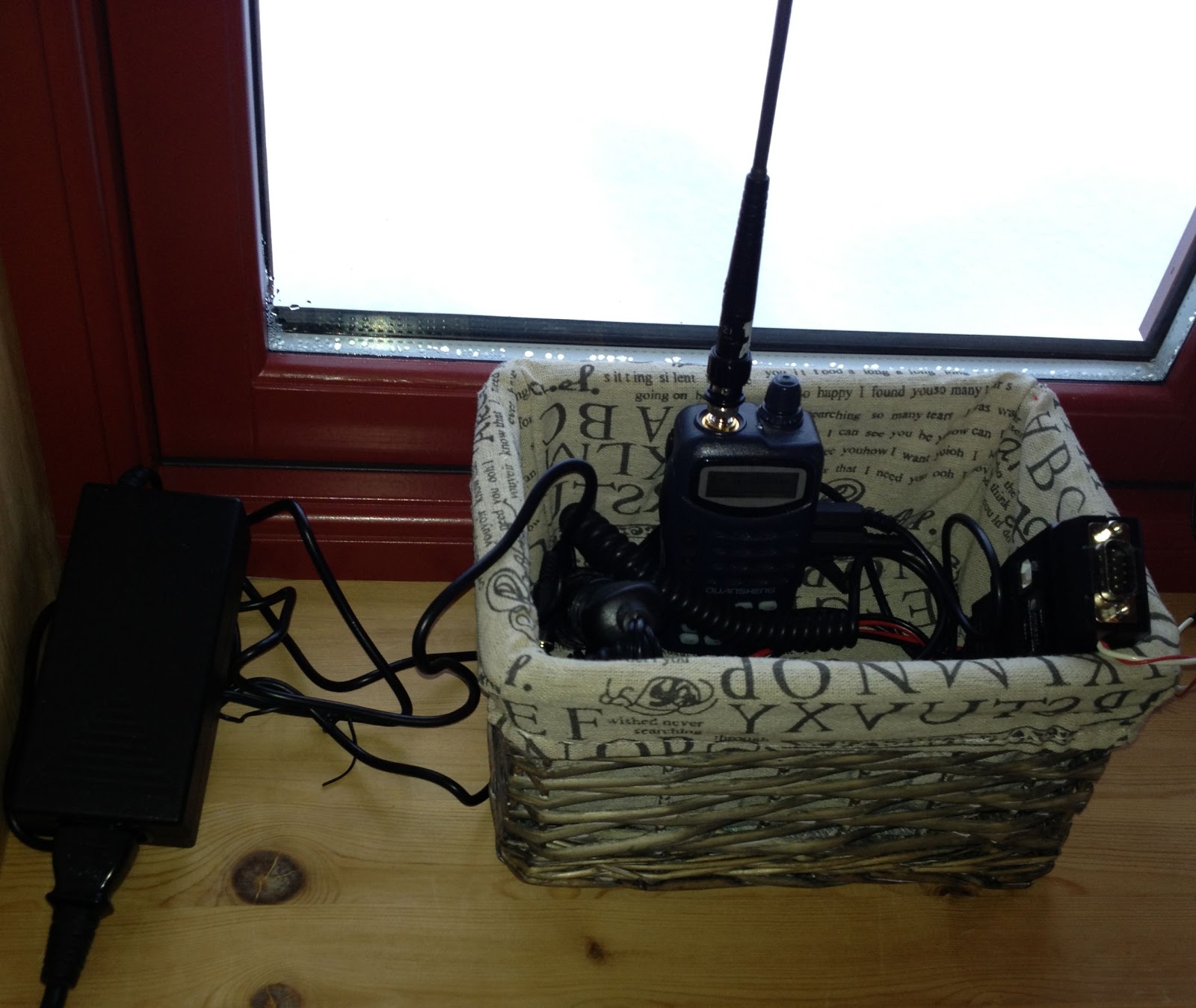
I use a Quanzheng TG-25AT handheld with a quarter-wave whip antenna on 144.800 MHz. Its signals reach the LD3GT digipeater at 1845 m above sea level. Although I don’t have direct line of sight, the low power (1 Watt) setting is adequate as the distance is only 10 km. The APRS-beacon is an OpenTracker USB set up for transmission every 15 minutes. An external DS18S20 temperature sensor which measures the outside temperature is connected to the 1-Wire® bus of the OpenTracker USB.
Thanks to the infrastructure providers: The Tønsberg group of NRRL (LA1T) who operate the LD3GT digipeater, probably the one with the largest coverage in Southern Norway (Gaustadtoppen). Thanks also to the various operators who receive packets from LD3GT and pass them on to the internet, and thanks to aprs.fi for processing and displaying the data on their excellent web site!
The most interesting contact in the CQ WW Contest

Sometimes looking up remote stations on QRZ.com or other sites gives a glimpse of the person behind the callsign. I did this for the Chinese station BY5CD which I contacted on 40 m during the CQ Worldwide contest this weekend.
It turned out to be a club station called “YinZhou Middle School Amateur Radio Club Station” which is located just south of Shanghai.
It is interesting to consider the age of the operators as one can see from the picture. More pictures and some information can be found on their QRZ.com website. With this many young people entering ham radio in China, maybe we will see more stations there in the future. The number of stations is unreasonably low compared to the enormous population of China.
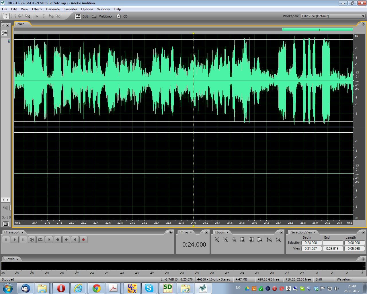 And the most interesting signal was that of GM5X on 21 MHz at 1207 UTC on 25. November. It had a distinct echo which seems to indicate that the signal travelled both on the direct path of about 800 km and the long path of about 39200 km.
The image shows “GM5X GM5X Test”. The long path signal seems to fade in and out as there is much less of it in the last part, the word “test”, than in the second “GM5X”.
F/LA3ZA on Long Delayed Echoes
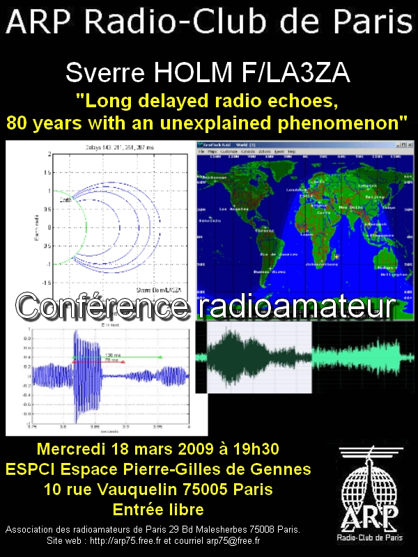
Laurent, F6GOX, who is one of the primary forces behind the ARP, Radio-Club de Paris, has written a nice little French-language presentation of me since I am a former member of the club. It also includes my interest in Long Delayed Echos (LDE).
Here he also talks about the presentation I gave for the Paris club of radio amateurs on 18 March 2009 on this subject during my year-long stay in Paris. That was a very nice evening which I remember with pleasure.
I also talked then about the interest that the French general Gustave Ferrié (1868 – 1932) took in this phenomenon (The link is in French, but read about Ferrié here in the English Wikipedia). There were French studies of LDEs in Indochina, Senegal, and Mauretania, French territories at the time, which he played a major role in.
Merci Laurent!
Visiting 409shop in Hong Kong

A stop-over on my way from Sydney to Oslo gave me the opportunity today to visit Apliu street in Hong Kong. This is where all the electronics products are found. As I had purchased a Baofeng UV-5R from them before it was fun to stop by the 409shop as well. Their address is on their web site, and the word “showroom” really made me expect something larger than what I found. It turns out to be just one small store among hundreds of others in this street.
I bought a handheld frequency counter, Yaege FC-1, and a better antenna, Nagoya NA-666, for the UV-5R and got a good deal – I like to think that it is because I presented myself as a previous internet customer.
On the other side of the street there was another store with communications equipment as well, Yee Fu Technology Shop, where I bought a 13.8V/20 A switch mode power supply, HK Products Electronics SPS-200MA.
It even had a noise-offset control which I have come to appreciate in my other power supply, the Alinco DM-330MV. It is particularly nice to have on 160 m. How they avoid Alinco’s pending patent on this feature is something I don’t know. There seems to be several other supplies on the market with this feature also, such as the Watson Power-Mite-NF (NF for Noise offset Function), so maybe Alinco’s patent application hasn’t been granted?
A Useless Machine with delay and howl
The useless machine or ultimate machine originates from Claude Shannon, the scientist who figured out how to find the channel capacity in a communications system. I bought the basic machine as a kit from Solarbotics.
But then I added a few features:
- A delay circuit that makes it look more alive as it gives the impression of doing some thinking before it responds to the switch.
- Sound that varies with how open the lid is and the amount of light that hits the photosensitive resistor. It was inspired by the design of the Growl and Scream Altoids of FightCube.
- A couple of LEDs, a red one when it opens and a blue one when it closes.
The circuits were built on small pieces of veroboard and the circuit diagram can be downloaded from here. In retrospect I’m not completely happy with the sound, it could have growled and screamed even more, but then how much effort can one really justify putting into a project which is – useless – anyway?
My first 24 hours on WSPR

My first beacon on 30 m, a free-running Ultimate QRSS kit (no GPS) has now been running for a full 24 hours using the Weak Signal Propagation Reporter (WSPR) mode. The figure comes from the WSPRnet page.
With an output power of about 150 mW to an 80 m horizontal loop it has not been possible to reach beyond Europe so far. Perhaps this will happen in the future with better conditions and/or with some more output power.
Added 26.9.2012: I made it for the first time across the Atlantic!
Timestamp Call MHz SNR Drift Grid Pwr Reporter RGrid km az
2012-09-26 00:50, LA3ZA, 10.140262, -26, -2, JO59fu, 0.2, WB2EEE, FN21xh, 5852, 290


