Author Archive
 Just good enough 10 MHz reference
Some time ago I noticed that the Ublox Neo-7M GPS has a 10 MHz output which was locked to the GPS system’s accuracy. Most people kept saying how much jitter it had and how useless it was unless it was cleaned up with a phase locked loop of some sort.
At the same time I got the 10 MHz reference input for my Elecraft K3 (K3EXREF). What struck me was how its function was described:
- The frequency of the internal oscillator of about 49.38 MHz oscillator would be continuously measured and averaged, obtaining a value to the nearest 1 Hz.
- The K3EXREF does not phase lock the K3’s reference oscillator and the external 10 MHz source has no impact on the K3’s phase noise performance.
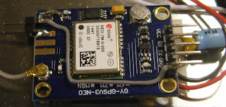
This got me wondering if the Neo-7M would be just good enough as a reference and that all the averaging internally to the K3 would take care of its jitter. I ordered one from Ebay for USD 12-13 together with an USB interface (USD 1.5) and hooked it up. The result is shown above as assembled in a clear top tin. In my shack I can receive GPS indoors, so I have no need for an external antenna
 The K3 accepts the input and I see the star in REF*CAL blinking. Just after turn-on of the K3 my reference frequency ends in … 682 and after 10-15 minutes it has fallen and stabilized to …648, i.e. 34 Hz down in frequency. This is just 8 Hz off the reference value I determined manually was the right one when my K3 was new in 2009 (49,379,640).
All this taken together indicates to me that the K3 finds this 10 MHz acceptable for locking.
In order to get this to work I had to do some modifications to the GPS unit. First I had to get access to the timepulse on the chip’s pin 3. My connection is inspired by that of G4ZFQ and consists of a small wire to the upper left hole. From there another grey wire goes below the chip and to the 5-pin header which is soldered to the Vcc, Rx, Tx, Gnd pins. The 5th pin is cut off and is just attached to the other pins through the plastic hardware.
The second modification was required in order to get it to run from the somewhat noisy USB 5 Volt supply. That took some decoupling between the Vcc and Gnd pins (220 uF and 0.1 uF in parallel), visible to the right in the image above, using good engineering practice to keep the wires as short as possible.
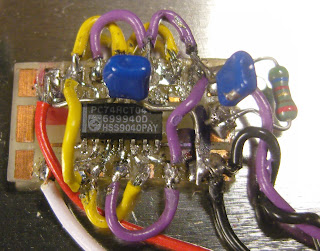 The timepulse is a 3.3 Vp-p output which cannot drive anything below 4-500 ohms impedance. Therefore I added a 74HCT04 driver that I have assembled on a little homemade SMD to DIL adapter PCB. It serves as a driver to feed the 10 MHz to the 50 ohm input of the K3EXREF.
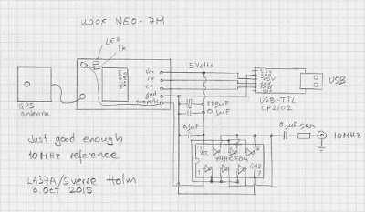
The HCT04 IC has 6 inverters. One of them takes the input signal from the timepulse output of the GPS IC and buffers it to drive the 5 other inverters in parallel. This is shown in the schematics at the end of this blog post.
The 5Vp-p output from the buffers is fed via 56 ohms to a connector that goes to the K3EXREF input. This is in accordance with the K3EXREF manual which says: “The 10 MHz source should have a signal level between +4 dBm and +16 dBm, nominal. For square wave sources, 2VDC to 3.3VDC peak is optimum. If the source is a 5V logic level, use a 50-ohm resistor in series with the input.“
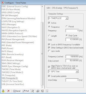 In order to set up the GPS I have used the u-center program (Menu: View, Configuration View, TP5 (Timepulse 5)) from Ublox and set it up with the parameters shown to the right. It blinks at 4 Hz before the signal is acquired and then switches to 10 MHz. This can be observed on the green LED connected to the Timepulse output also as it switches from blinking to a half-lit status.
  Just good enough 10 MHz GPS reference
Some time ago I noticed that the Ublox Neo-7M GPS has a 10 MHz output which is locked to the GPS system’s accuracy. Most people kept saying how useless it was due to excessive jitter unless it was cleaned up with a phase locked loop of some sort.
At about the same time I installed the external reference input for my Elecraft K3. The K3EXREF enables the K3’s frequency to be locked to an external 10 MHz reference. What struck me was how its function is described:
- The frequency of the internal oscillator of about 49.38 MHz is continuously measured and averaged, obtaining a value to the nearest 1 Hz.
- The K3EXREF does not phase lock the K3’s reference oscillator and the external 10 MHz source has no impact on the K3’s phase noise performance.
This got me wondering if the Neo-7M would be just good enough as a reference and that all the averaging internally to the K3 would take care of the jitter. I ordered one from Ebay for USD 12-13 together with an USB interface (USD 1.5) and hooked it up. (Actually the NEO-7M already has a built-in USB interface, but my board doesn’t support it). The result is shown above as assembled in a clear top tin. In my wooden house I can receive GPS indoors, so I have no need for an external antenna
 The K3 accepts the input and I see the star in REF*CAL blinking. Just after turn-on of the K3 my 49.38 MHz reference frequency ends in …682 and after 10-15 minutes it has fallen and stabilized to …648, i.e. 34 Hz down in frequency. This is just 8 Hz off the reference value I determined manually was the right one when my K3 was new in 2009 (49.379.640).
All this taken together indicates to me that the K3 finds this 10 MHz acceptable for locking. The measurement to the nearest Hz, implies a measurement time of the order of 1 second and that seems to be enough to smooth out the jitter from the Neo-7M.
In order to get this to work I had to do some modifications to the GPS unit. First I had to get access to the timepulse on the chip’s pin 3. My connection is inspired by that of G4ZFQ and consists of a small wire from the left-hand side of the 1k resistor to the upper left hole. From there another grey wire goes below the chip and to the 5-pin header which is soldered to the Vcc, Rx, Tx, Gnd pins. The 5th pin is cut off and is just attached to the other pins through the plastic hardware.
The second modification was required in order to get it to run from the somewhat noisy USB 5 Volt supply. That took some decoupling between the Vcc and Gnd pins (220 uF and 0.1 uF in parallel), visible to the right in the image above, using good engineering practice to keep the wires as short as possible.
 The timepulse is a 3.3 Vp-p output which cannot drive anything below 400-500 ohms impedance. Therefore I added a 74HCT04 driver that I have assembled on a little homemade SMD to DIL adapter PCB (easy to find on Ebay). It serves as a driver to feed the 10 MHz to the 50 ohm input of the K3EXREF.
The HCT04 IC has 6 inverters. One of them takes the input signal from the Timepulse output of the GPS IC and buffers it to drive the 5 other inverters in parallel. This is shown in the schematics at the end of this blog post.
The 5Vp-p output from the buffers is fed via 56 ohms to a connector that goes to the K3EXREF input. This is in accordance with the K3EXREF manual which says: “The 10 MHz source should have a signal level between +4 dBm and +16 dBm, nominal. For square wave sources, 2VDC to 3.3VDC peak is optimum. If the source is a 5V logic level, use a 50-ohm resistor in series with the input.“
 In order to set up the GPS I have used the u-center program (Menu: View, Configuration View, TP5 (Timepulse 5)) from Ublox and set it up with the parameters shown to the right. It blinks at 4 Hz before the signal is acquired and then switches to 10 MHz. This can be observed on the green LED connected to the Timepulse output also as it switches from blinking to a half-lit status.
 See also
 The LM386 Pixie challenge
The Pixie 2 is this minimal transceiver which I and many others have played around with and had lots of fun with. My 80 m version is shown to the right, but right now it is very popular with some incredibly cheap Chinese ones on sale on Ebay and other places.
The Pixie 2 uses the versatile LM386 amplifier for its audio output. I have shown previously on this blog how its gain can be boosted and how it can implement a CW filter, and also how the muting can be improved. However, during transmission, the LM386 just sits there idle, although it can be used to amplify a sidetone from an external oscillator.
But I’m sure the old 70’s LM386 can do better than this. Despite its age, recently some pretty amazing uses of this chip have been demonstrated. It can be used as a regenerative receiver at least up to medium wave frequencies and it can also be used as an envelope detector/demodulator.
The LM386 challenge is this: Is is possible to implement a sidetone oscillator for the Pixie using only the LM386 with as few other components as possible? The output level needs to be controllable in order to make it comparable to that of the Pixie in the receiver mode.
The best data sheet for the LM386 seems to be the one for NJM386 from New Japan Radio Co. It is, as far as I know, the only one which shows the various muting circuits including the one using pin 7 which I have explored. It also shows the LM386 as an oscillator: both a sinusoidal and a square wave one.
In order for the LM386 to be useful as a sidetone oscillator, I believe that the oscillation must take place in the input circuitry. That seems to be the only way to ensure that the output doesn’t come out at a blasting full rail-to-rail swing as in the square wave oscillator example in the data sheet.
By the way, the data sheet referred to above is also the basis for the improved Spice model for the LM386 that just was developed. It came partly as a response to my complaint over how poor the present one was. Maybe the new Spice model, developed by EasyEDA, could help solve the LM386 challenge?
 The LM386 Pixie challenge
The Pixie 2 is this minimal transceiver which I and many others have played around with and had lots of fun with. My 80 m version is shown below, but right now it is very popular with some incredibly cheap Chinese ones on sale on Ebay and other places.
The Pixie 2 uses the versatile LM386 amplifier for its audio output. I have shown previously on this blog how its gain can be boosted and how it can implement a CW filter, and also how the muting can be improved. However, during transmission, the LM386 just sits there idle, although it can be used to amplify a sidetone from an external oscillator.
But I’m sure the old 70’s LM386 can do better than that. Despite its age, recently some pretty amazing uses of this chip have been demonstrated. It can be used as a regenerative receiver at least up to medium wave frequencies and it can also be used as an envelope detector/demodulator.
The LM386 challenge is this: Is is possible to implement a sidetone oscillator for the Pixie using only the LM386 with as few other components as possible? The output level needs to be controllable in order to make it comparable to that of the Pixie in the receiver mode.
The best data sheet for the LM386 seems to be the one for NJM386 from New Japan Radio Co. It is, as far as I know, the only one which shows the various muting circuits including the one using pin 7 which I have explored. It also shows the LM386 as an oscillator: both a sinusoidal and a square wave one.
In order for the LM386 to be useful as a sidetone oscillator, I believe that the oscillation must take place in the input circuitry. That seems to be the only way to ensure that the output doesn’t come out at a blasting full rail-to-rail swing as in the square wave oscillator example in the data sheet.
By the way, the data sheet referred to above is also the basis for the improved Spice model for the LM386 that just was developed. It came partly as a response to my complaint over how poor the present one was. Maybe the new Spice model, developed by EasyEDA, could help solve the LM386 challenge?
 Regenerative receiver based entirely on the LM386
I got a tip the other day that there is an interesting circuit over at the RadioBoards Forum where an LM386 IC is used as a regen receiver for the medium wave band. It is the user ‘Selenium’ who has come up with that circuit. I think it is quite an amazing application of this IC – so here it is:
 |
| LM386 as a medium wave regen receiver by user Selenium on RadioBoards Forum |
Interestingly, both the + and – inputs are tied together (pins 2 and 3). It is also quite unusual to connect pin 7 to anything but capacitors (for bypass or extra input as I have done), so that may change the bias of the input stage. Further, the smaller the impedance from pin 1 to ground, the larger the gain (here 10 uF in series with 1k).
If you want to read more about the regen circuit, go to the RadioBoards Forum here.
 Regenerative receiver based entirely on the LM386
I got a tip the other day that there is an interesting circuit over at the RadioBoards Forum where an LM386 IC is used as a regen receiver for the medium wave band. It is the user ‘Selenium’ who has come up with that circuit. I think it is quite an amazing application of this IC – so here it is:
 |
| LM386 as a medium wave regen receiver by user Selenium on RadioBoards Forum |
Interestingly, both the + and – inputs are tied together (pins 2 and 3). It is also quite unusual to connect pin 7 to anything but capacitors (for bypass or extra input as I have done), so that may change the bias of the input stage. Further, the smaller the impedance from pin 1 to ground, the larger the gain (here 10 uF in series with 1k for low frequencies and 100 pF for high frequencies).
If you want to read more about the regen circuit, go to the RadioBoards Forum here.
 CQ WPX made my day
From time to time I have heard of those of who manage to contact 100 DXCC countries during one weekend. This past weekend it was my turn to try.
If you have a contest station with 1 kW and monoband yagi antennas, then this goal shouldn’t be too hard. But for my station with only an 80 m horizontal loop (loop skywire) circling its way through my garden from treetop to treetop and 100 W of transmitter power from my K3, the challenge was greater.
About 6 hours before the end of the test and with 87 countries, I had almost given up so I sent the tweet above. The status for the second day of the contest was that I had only worked two more countries.
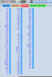 But then in the final hours I heard and then contacted Tunisia, Malaysia, Australia og Kosovo (Z6) to bring me to 91, and then Laos and Albania. But then it took a long while for some new ones: Spanish Africa (EA9) and Argentine. I also managed two more Caribbean stations (J3 and CO) and Peru and Sardinia.
Finally in the last hour of the contest two more Caribbean stations (PJ2 and VP9) and in the end Mexico 21 minutes before the end of the contest. That brought the total to 102. I think that was needed as Kosovo isn’t really an approved country and I also had contact with what was probably a pirate and not a station from Andorra. That signature was C31XR which most likely is the name of an antenna and not a real station.
My total was 47 European countries, 19 from Asia, 12 from North America, 10 from Africa, 9 from South America and 3 from Oceania. I think it helps to be in Europe as I had almost half of the countries quite close by, but it would be interesting to hear comments from North Americans on how realistic they consider this goal to be from their location.

