Author Archive
 First 475 kHz WSPR decoding
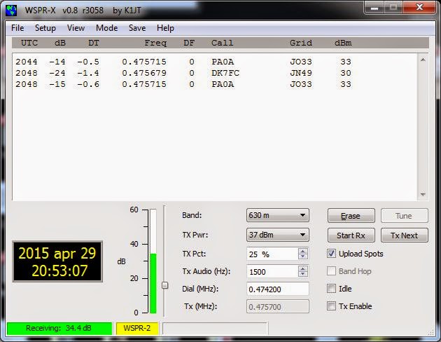
Tonight I made the first successful decoding of WSPR on the 630 m band. What inspired me was all the talk on the Elecraft reflector on the new synthesizer which in addition to having less phase noise, also allows the K3 to go below 500 kHz. I don’t have that synthesizer, but the discussion reminded me of the low frequency converter I built many years ago. It converts 0-1 MHz to 14-15 MHz. Using the KXV3 transverter interface of the K3 it was easy to interface and get up and running.
The first signals I decoded are shown in the water fall above, and their origin in Germany and the Netherlands is shown in the next figure.
According to WSPRnet, PA0A’s 2 Watt transmitter is 784 km away from me, and DK7FC’s 1 Watt is 1164 km away.
The converter is based on a 74HC4053 switch used as a mixer with a 74HC04 for a 14 MHz oscillator. It is based on SM6LKM’s design, but with a different oscillator frequency and a simplified output filter. It is one of many small projects that I have built in Altoids tins. The antenna used was my trusty old 80 meter horizontal loop with a 4:1 Elecraft balun.
Perhaps the next step is to finish the 475 kHz filter of my Ultimate 3 WSPR transmitter and see if others can receive me? That is going to be more of a challenge antenna-wise.
 First 475 kHz WSPR decoding
Tonight I made the first successful decoding of WSPR on the 630 m band. What inspired me was all the talk on the Elecraft reflector on the new synthesizer which in addition to having less phase noise, also allows the K3 to go below 500 kHz. I don’t have that synthesizer, but the discussion reminded me of the low frequency converter I built many years ago. It converts 0-1 MHz to 14-15 MHz. Using the KXV3 transverter interface of the K3 it was easy to interface and get up and running.
The first signals I decoded are shown in the water fall above, and their origin in Germany and the Netherlands is shown in the next figure.
According to WSPRnet, PA0A’s 2 Watt transmitter is 784 km away from me, and DK7FC’s 1 Watt is 1164 km away.
The converter is quite simple and is based on a 74HC4053 switch used as a mixer with a 74HC04 for a 14 MHz oscillator. It is the design of SM6LKM, but with a different oscillator frequency and a simplified output filter compared to his. It is one of many small projects that I have built in Altoids tins.
The antenna used was my trusty old 80 meter horizontal loop which has been the main work horse for making my 8-band DXCC (more than 100 countries on all bands 3.5 – 28 MHz) possible. It is fed with ladderline into a 4:1 Elecraft balun in the shack.
Perhaps the next step is to finish the 475 kHz filter of my Ultimate 3 WSPR transmitter and see if others can receive me? That is going to be more of a challenge antenna-wise.
 A beauty of a crystal radio
This past weekend during Hammeeting – the largest Ham rally in Norway – I met Per LA9DTA.
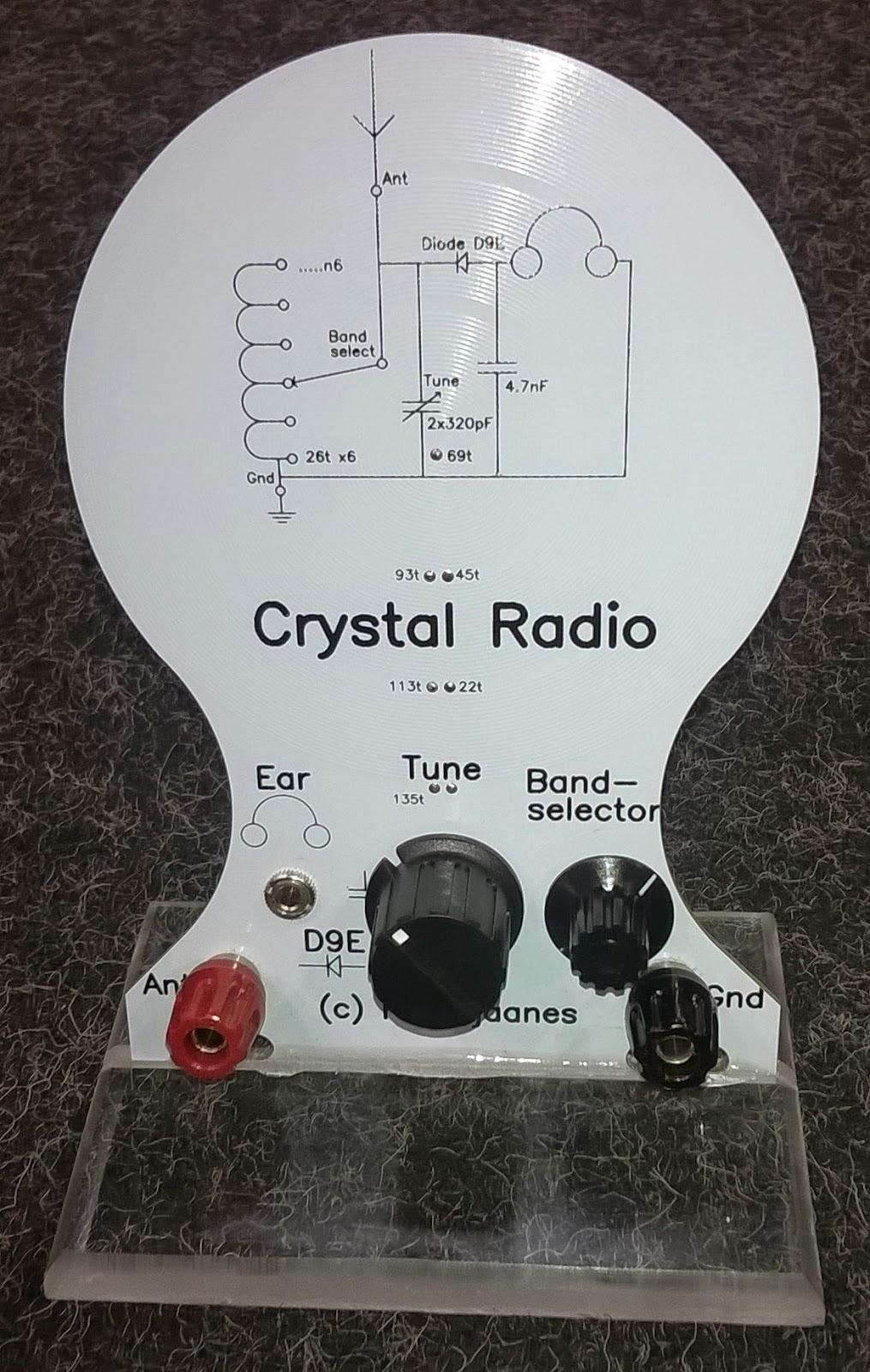
He showed me his beautiful crystal radio. It can be seen in the center of the table, with some close-ups below. The design has a printed coil and the whole design is made on a PCB which was shaped as shown in the image. It has a bandswitch and a Ge diode.
I fell for his design, but with the lack of longwave and medium wave transmitters here I am not sure if I would have much use for it. That is unless I set up one of my transmitter projects to support a radio like this.
 A beauty of a crystal radio
This past weekend during Hammeeting – the largest Ham rally in Norway – I met Per LA9DTA.
He showed me his beautiful crystal radio. It can be seen in the center of the table, with some close-ups below. The design has a printed coil and the whole design is made on a PCB which was shaped as shown in the image. It has a bandswitch and a Soviet low forward voltage Ge diode.
I fell for his design, but with the lack of longwave and medium wave transmitters here I am not sure if I would have much use for it. That is unless I set up one of my transmitter projects to support a radio like this.
 Car upgrade to LEDs
It was time to upgrade the interior lights in my 2004 Volvo. I got some lamps from Ebay specified as LED Festoon, 80-85lm, 12V. As many others have experienced they kept on glowing faintly after the door was closed. When the ignition was turned off the lamps were completely off also, so there was no danger of draining the battery. Still it is not the way one expects lamps to behave.
One can get more expensive LED lamps which avoid this faint glow, “Canbus error free” seems to be the way to specify this. But mine were of the plain type, and the problem seems to be the leakage current in the FET switches that turn the lights on and off.
All it takes to solve it is a parallel resistor. Some have used 1k, others larger values. I just made some trials and found that 10k worked well. The advantage is that 10k will only dissipate 18 mW @13.5 Volts, while the 1k will dissipate ten times that, so I could use a small 1/4 W type. I soldered it on the back of the board as the image shows.
The reason for switching to LED is not really to save energy as the savings aren’t that great anyway. The whiter and brighter light is more important as you can see in the image with the LED to the left and the old incandescent lamp to the right.
While at it, I just had to do some reverse engineering of the LED lamps. There seems to be four parallel groups of three series-connected LEDs (the three in a row) giving a forward voltage of about 8.3 V. They are driven via a resistor of 120 ohms in series with what seems to be a bridge rectifier since the lamps don’t depend on being connected in a particular way with respect to polarity. They draw 18 mA @ 12V and 28 mA @ 13.5 V. This is not a very fancy way of constructing a LED lamp as there is no constant current regulation. The intensity will therefore vary with voltage, but hopefully it will work well here.
 Car upgrade to LEDs
It was time to upgrade the interior lights in my 2004 Volvo. I got some lamps from Ebay specified as 42 mm LED Festoon, 80-85 lm, 12V. As many others have experienced also, they kept on glowing faintly after the door was closed. But when the ignition was turned off the lamps were completely off also, so there was no danger of draining the battery. Still this is not the way one expects lamps to behave.
One can get more expensive LED lamps which avoid this faint glow, “Canbus error free” seems to be the way to specify this. But mine were of the plain type, and the problem seems to be the leakage current in the FET switches that turn the lights on and off. It is tiny, but enough to give a voltage large enough to turn the LEDs on. An additional resistor load will lower the voltage below that threshold.
This requires a parallel resistor. Some have used 1k, others larger values. I did some trials and found that 10k worked well, while 22k didn’t completely eliminate the faint glow. The advantage is that 10k will only dissipate 18 mW @13.5 Volts, while the 1k will dissipate ten times that. Therefore I could use a small 1/4 W type. I soldered it on the back of the LED-board as the image shows.
The reason for switching to LED is not really to save energy as the savings aren’t that great anyway. The whiter and brighter light is more important as you can see in the image with the LED to the left and the old incandescent lamp to the right.
While at it, I just had to do some reverse engineering of the LED lamps. There seems to be four parallel groups of three series-connected LEDs (the three in a row) giving a forward voltage of about 8.3 V. They are driven via a resistor of 120 ohms in series with what seems to be a bridge rectifier since the lamps don’t depend on being connected in a particular way with respect to polarity.
In total it draws 18 mA @ 12V and 28 mA @ 13.5 V, i.e. 0.3-0.4 W, compared to 10 W for the bulb it replaced. This is not a very sophisticated way of constructing a LED lamp as there is no constant current regulation. The intensity will therefore vary with voltage, but hopefully it will work well here.
 All continents in one night on WSPR
For me South America, Australia, and Africa are quite rare on WSPR. But they all heard my tiny 0.2 W signal the night between 31 March and 1 April in addition to North America, Asia and Europe. That’s a new one for me and worthy a brag post on the blog, I think! Hopefully, it may also inspire others to try low power WSPR.
In Australia and South America I was heard on the 10 MHz band, in Africa on 21 MHz, in Pakistan on 14 MHz, while 7 and 10 MHz worked into Siberia. North American stations also heard me on the 7 and 10 MHz bands.
This was on my untuned 80 m horizontal loop fed with open-wire feeder and a 4:1 balun. This shows both that the bare-foot Ultimate 3 kit is very tolerant of loads with SWR much different from 1, and that WSPR gives amazing results.


