Author Archive
 All continents in one night on WSPR
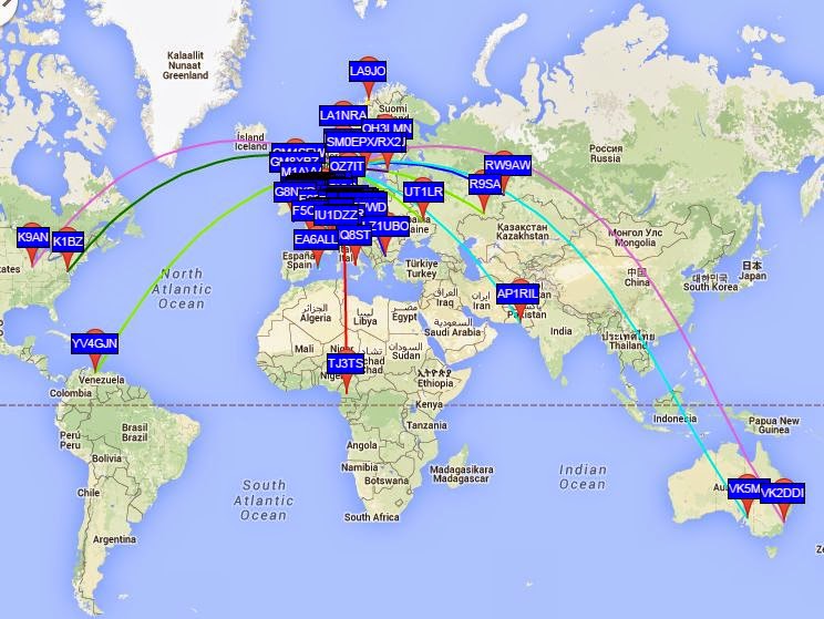
For me South America, Australia, and Africa are quite rare on WSPR. But they all heard my tiny 0.2 W signal the night between 31 March and 1 April in addition to North America, Asia and Europe. That’s a new one for me and worthy a brag post on the blog, I think! Hopefully, it may also inspire others to try low power WSPR.
In Australia and South America I was heard on the 10 MHz band, in Africa on 21 MHz, in Pakistan on 14 MHz, while 7 and 10 MHz worked into Siberia. North American stations also heard me on the 7 and 10 MHz bands.
This was on my untuned 80 m horizontal loop fed with open-wire feeder and a 4:1 balun. This shows both that the bare-foot Ultimate 3 kit is very tolerant of loads with SWR much different from 1, and that WSPR gives amazing results.
 Low power longwave transmitter experiment
Many places in the world, low power transmitters in the medium wave band are allowed. I am talking about regulations like in the US where FCC part 15 allows up to 100 mW input.
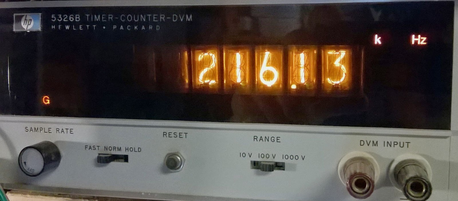
In Norway we have a particular permission for members of the Norwegian Radio Historic Society to transmit up to 500 mW on 216 kHz. I’m not sure if this is output or input power. The permission is meant to cover a collection of historic radios. The frequency is the one used by the main transmitter north of Oslo from 1954-1995 running 200 kW. The frequency is still allocated to Norway, so I guess that is why we may use it this way.
 I grew up close to this transmitter and have fond memories of my first homemade crystal set receiving this station.
There are several low power transmitters around that can be purchased, but most of them only cover the mediumwave band and not longwave (153-279 kHz). Further they are quite complicated as the frequency necessarily has to be user settable.
I looked for a simpler way to make a single-frequency transmitter and found that the function generator chip XR-2206 which I happened to have in my junk box could both generate this frequency and do the amplitude modulation. The RC-oscillator seems to be stable enough for this low frequency although I haven’t tested this much.
Here are the first results with images of the circuit on a Veroboard and the oscilloscope picture of the modulation with my Tandberg TP41 70’s radio on top of it listening to Dire Straits from Spotify streaming over longwave.
 The circuit has very little output power, lacks antenna tuning and harmonic filtering, so there is room for improvement, but at least it works.
Too bad that the XR-2206 is obsolete and not recommended for new development!
 Finally got my Ultrafire WF-501B as I wanted it
As I wrote in my blog post a few days ago, I got the intensity down for night vision for my red flashlight. But I wasn’t quite happy with the level and wanted to reduce it even more. To do that I had to unsolder 6 of the 8 AMC7135 350 mA constant current ICs on the PCB of the AMC7135*8 2800mA 4-Group 5-Mode Circuit Board.
These constant current chips are all run in parallel with the VDD input for control. The 8-pin Atmel ATtiny13A chip controls all VDD inputs in parallel from its pin 6. When the VDD pin is low there will be now light. I haven’t measured this, but I am assuming that this pin is pulsed in order to reduce current down from the maximum.
My measurements for the High, Medium, and Low settings are:
- 8 chips: 2,8 A, 0.83 A, 0.14 A
- 4 chips: 1,4A, 0.45 A, 0.08 A
- 2 chips: 700 mA, 225 mA, 42 mA
This scales as expected with the number of 350 mA chips and the 100%, 30%, and 5% settings of the controller. Now only Q1 and Q3 remain, and Q2, Q4-8 have been desoldered.
One could have obtained en even more battery-friendly version if somehow the original controller could have been modified. The step-down circuit is quite standard with an inductor, a Shottky diode (SS14), and a controller chip of unknown origin. But it seems to me that if R23 of value R250 (0.25 ohm) was increased, output current would probably go down.
As it is I am much more happy with the intensity of the settings I have now. It will be a good companion night light which will preserve night vision well when used with a telescope.
 Dimming my Ultrafire WF-501B
I got this red LED flashlight as a Christmas present. But unfortunately the intensity was way too high for what I intended to use it for. A soft red light preserves your night vision, and is ideal for use with a telescope in the dark as was my intention. But if the intensity was as high as before the modification, night vision would suffer.
I then found this YouTube video describing how the controller circuit board could be replaced by one with more functions. As recommended I therefore ordered an AMC7135*8 2800mA 4-Group 5-Mode Circuit Board with 8 AMC7135 current regulators in parallel. The image shows the the original circuit board as connected before the modification in the front in the image and the new one behind it.
The new board gave me the choice of one of 4-groups:
- 3-mode: Lo (5%) – Hi (100%) – Strobe
- 3-mode: Lo (5%) – Mid (30%) – Hi (100%)
- 2-mode: Lo (10%) – Hi (100%)
- 5-mode: Lo (5%) – Mid (30%) – Hi (100%) – Strobe – SOS
 Hardly any young people are becoming hams anymore
This is what Ed Muns, W0YK, said in an interview the other day, and goes on with “because they see this as kind of old school stuff.“
A year ago the ARRL web site said: “Amateur Radio showing steady growth in the US“. AH0A’s website with statistics over the US ham population backs this up with the curve shown here. Even in my local club we are now seeing young people signing up for licence classes.
How different perspectives! How has an old radio amateur like W0YK come to believe in the myth of declining numbers of hams?
 0.2 Watts to South Africa
 Getting ready for 60 meter
I have never had any contacts on the 5 MHz or the 60 meter band. But I guess it’s time for that now.
Both my K2 and my K3 support it and about 40 countries now have access to this band according to K1ZZ in his column “It seems to us” in this month’s QST.
As a first test I ran my 0.2 W Ultimate 3 GPS-controlled WSPR transmitter over night and the image shows the result. I am using an 80 m long loop skywire antenna (horizontal loop) tuned to 60 m.
The results were encouraging with the best DX being UR5VIB in Ukraine at a distance of 1887 km. By the way, considering that it is 1093 km to LA9JO in the north of Norway, one sees the distortion in the map projection used for the Google map.
I have also operated the antenna as a vertical (about 8 meters) with top-hat loading by tying both feed-line conductors together and feeding it against a ground plane. The result is quite similar. The article by Dave Fischer, W0MHS called “The Loop Skywire” in QST November 1985 is the reference for both uses of the loop. The article starts out with this catchy phrase: Looking for an all-band HF antenna that is easy to construct, costs nearly nothing and works great DX? Try this one! This matches my experience exactly as this antenna has been instrumental for my 8 band DXCC.


