Author Archive
 CQ WW CW contest wrap up
 CQ WW CW DX contest this weekend!
This weekend the bands will be alive with CW for the CQ WW CW DX contest. If you are not a contester this still is a great weekend to grab some DXCCs for your log book towards an award. If you are a CW contester then hold on and enjoy. Today I spent some time making sure the Hustler 4BTV vertical was ok, updated my contesting software N1MM+, ran a check on the macros and made sure the trusty Icom 7610 and the 9AN5 touch keyer are ready to go. I am hoping Murphy will stay far away this weekend and allow me to enjoy the music of morse!
 For those Icom 7610 owners a different way to work split.
 |
| Fixed mode with 20kHz span |
I have had my Icom 7610 for several years now and am still very much enjoying it. From time to time I enjoy working DXpeditions and having Dual receivers and dual spectrum scopes with the Icom 7610 is very handy. The spectrum scope has 2 tuning options which are fixed and center modes. It could just be me but I find center mode hard to follow were as fixed mode seems very easy to follow. When you come across a station that is working split more often than not it’s because there is a large pileup and it’s more efficient to work split. For those readers who are not certain what split operation is this LINK explains it better than I can.
During split operation especially with a very rare DX station, there are LOTS of operators trying to contact the prized DX station. For this reason on the DX’s listening frequency, there are many ops trying to make contact. When you as an operator want to get involved and try to contact the DX station you have to drop yourself in the pool of stations calling the DX station.
The trick is where to set your VFO dial to have a chance to be heard by the DX station. In most cases, the DX station has a routine to move up or down his listening frequency which is your transmit frequency. One must listen and watch the waterfall to see who the DX station is answering call after call. You can then get the idea if he is moving up or down his listening frequency and by how much.
As I said there could be lots of callers and this translates to a very crowded waterfall display. To find out where to drop your call one must have a closer look at the waterfall. When this is done you can get some separation between the calling stations. Thus allowing you to better see who the DX station is answering. Then you have a good idea when and where to drop your call and hopefully be heard.
As I said the center mode I find very confusing and when I use it in split mode and spin the VFO I am just lost as to who is where and for this reason I use fixed mode.
As a side note: In center mode when you spin the VFO the signals on the waterfall move and the VFO marker remains stationary. In center mode when the VFO is changed the waterfall signals remain stationary and the VFO marker moves to the next signal.
As was said earlier it is best to have a closer look at the waterfall to see the action. In fixed mode, the smallest slice of the band you can have is 20khz. When operating CW as I do this for me is not enough for a very crowded calling group. In center mode, you can get a slice all the way down to +/- 2.5kHz or +/- 5kHz. For me, these are great options and with CW I generally would choose +/-2.5kHz but the rig has to be in center mode and that just does not work for me.
I have found a workaround so I can use the center mode, select +/-2.5kHz and still have the moving VFO B marker and not a moving waterfall! Below are the setup steps I take to make this happen.
In fixed mode, I find the DX station with VFO A
I then press the Dual-W button
Then press and hold Dual-W button to get the settings for VFO B the same as VFO A
I then press the split button
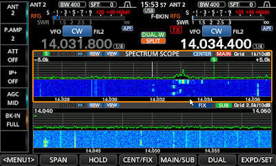
I press the Dual soft key my scope becomes over-under as this is how it is setup. You can see the dual scope view in the post pictures.
I change both scopes to center mode if not there already.
I now set the span to the same on each lower and upper scope in my case it is +/-2.5kHz I then touch VFO B frequency readout on the upper band scope (to activate VFO B)
Now in the upper band scope, VFO A remains stationary on the DX station. VFO B (in the upper band scope) now moves when the VFO dial is turned. The VFO marker moves (like fixed mode) and the band signals remain stationary.
The lower scope is still there but I don’t pay any attention to it. I found if I did not stay in dual scope mode I would lose the CENTER mode for VFO A and FIXED mode for VFO B.
 |
| 5+/-kHz in center mode but VFO acts like fixed mode |
Now with all this said I just know there is going to be a comment that informs me I can press 2 simple buttons on the rig and get the same results. I seem to always take the long way around with things. I have added some screen pics of how the waterfall looks when in 20kHz, +/-5kHz and +/-2.5kHz span during a DXpedition. As you can see when in +/-2.5kHz mode the calling station are easy to see compared to fix 20kHz and +/-5kHz selections. But best of all I have fixed mode operation of VFO B with these small spans.
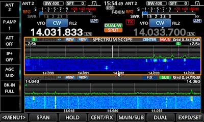 |
| +/-2.5kHz span view of pile up calling DX station |
 Time to make a choke balun
In your ham radio adventures, you may have heard the words..choke balun, feedline isolation, common mode choke or a 1:1 balun. In my humble opinion different names for the same device. These devices for the most part are present in a system to control common mode currents. I am not an engineer just a simple ham guy trying to sometimes understand some very complicated and technical explanations.
I hope to keep the next bunch of lines understandable. Here we go...what are common mode currents! Most ham use some form of 52 ohm coax as it's very easy to route, secure and can within reason be placed anywhere. Ideally, RF will flow out on the OUTER SURFACE of the coax INNER CONDUCTOR and flow back on the INSIDE SURFACE of the coax shield. This is what happens in a perfect world but if a system is unbalanced RF current will return on the OUTSIDE of the outer coax braid. It does not return but it radiates.
This is when we hams can experience RFI issues and these issues vary with the amount of common mode currents flowing on the outside of the shield of the coax. How does one control this common mode current? One very effective way is to introduce a common mode choke, 1:1 balun, choke, feed line isolation or whatever else it could be called.
In a previous post, I did go over how I installed a 1:1 balun at the antenna feed point of my Hustler 4BTV and that seemed to satisfy my RFI issues but further reading informed me that a choke balun at the radio feed point would be very advantageous. I ordered 2 FT240-31 mix toroids as I decided to make a choke balun instead of buying one. The two common mixes for HF toroids are 31 and 43. The difference being the 31 mix is effective from 1-300 Mhz and 43 is effective from 25-300 Mhz. I chose to go with the 31 mix and purchased 2 from a reputable dealer as not all toroids are created equal. I would be very wary if you find toroids at a very low price....just remember you get what you pay for. I ordered mine from Mouser Electronics Canada, part number 623-2631803802 made by Fair-Rite for 13.00 each.
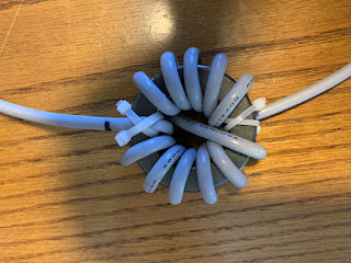
I used RG8X coax to wind around the toroid but the issue with using a ring toroid compared to a split bead is I had to remove the PL-259 to wind the coax around the toroid and then solder the PL-259 back on. I intended to make 10 loops and for some reason, I ended up with 11 turns through the toroid. I then soldered the PL-259 connector back on but not before placing the barrel and coax spacer on....how many of us have soldered a PL-259 on and then realized we forgot the spacer and barrel!
Another advantage to having a choke balun at each end of the coax is that it helps remove some RF noise that is picked up on the shield of the coax.
 |
| Dont forget these BEFORE soldering the PL-259 |
 Hustler 4BTV base cover.
 |
| Lower section before balun install. |
Autumn is here along with the leaves all over the lawn, once or twice a week I take the lawn mower out with the grass catcher on and vacuum the lawn of leaves. Doing this got me thinking of winter and my Hustler 4BTV antenna regarding the snow. I did some internet searches and some left the base alone while others covered it. The conscience was that snow does not bother the vertical with regards to performance but I was concerned about the connections and isolation balun.
I decided to make a box to cover the base section of the antenna but one that could easily come off in case of a storm and I had to lower the antenna. I wanted something simple, that would stand up to the weather and remove without issue. I came up with a cover made of wood and only 4 deck screws had to be removed to remove the box cover from the antenna for storage. The top also has 4 deck screws it can be removed for access to the antenna if it has to be taken down due to high winter winds.
I also made the box with room on the side as I knew I would be adding the choke balun to the mix. It's going to be painted white to mix in with the snow when it comes and I will keep on top of shovelling the snow on and around it just in case the antenna has to come down due to windy weather.
As said before to remove the box ultimately all that has to be done is 4 deck screws removed and the side cover and half of the top cover comes off and the box can be removed and stored for the summer. In case of poor winter weather, 2 deck screws are removed and half of the top cover is removed and the antenna base is exposed.
 |
| Room for the Balun |
 |
| Completed box to be painted |
The final picture shows 1/2 of the top cover removed and the lower screw clamp is exposed and can be loosened for the antenna to be removed. The cover goes back in place.
Read the rest of this entry »
 Time to add a balun.
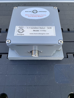
When I moved to the East coast from Ontario at the new QTH I purchased and installed an EndFed antenna and it worked great for me. It was a huge step up from the condo balcony mag loop antenna. The EndFed is a compromise-type antenna and does come with some issues. The main issue is (if you don't use a counterpoise) the coax shield is used as the counterpoise. This can cause some issues and an isolation balun is needed in the shack. I purchased a quality isolation balun from balun designs to take care of the feed line issues. In time I did install a counterpoise but it's not that effective when your Endfed goes from 10m-80m.
I still had some RFI issues in the shack that ferrites did an excellent job in looking after. I still had some off-and-on issues with our electronic washing machine, the motion sensor light on the shed and some Google home devices. I then moved from the EndFed to a vertical antenna the Hustler 4BTV antenna. In the manual for the 4BTV, it is advised if you have any RFI issues due to the coax radiating RF place an isolation balun at the antenna. It seemed as time passed I was issue free. 
Drainage holes 1/16th
Now and then I started to notice while operating my Icom 7610 in CW mode I would have my N1MM contest program lock up. There was no rhyme or reason as to when this happened, what power level and what band I was on. I could make it through a CWops mini-test of an hour with no issues. The next CWops mini contest I had nothing but issues. I also noticed when using my VPN on the PC I would have the VPN disconnect and then reconnect messages coming up as I transmitted. I was reading online when coax radiates RF it can be very hit-and-miss as to when it happens and what is affected each time. This sounded like the issue I was having and I decided to place the isolation balun at the base of the 4BTV vertical.
Once the isolation balun was installed I am RF free and have been for over a month now. My electronic washing machine, N1MM logger and VPN connection have no problems. 
Waterproof connections
I had to take into consideration some precautions when putting the isolation balun outdoors. It was recommended to drill 2 1/16 holes in the bottom so any condensation would not build up inside. Also around all PL-259 connections, I waterproofed them with self-amalgamating tape.
 A weekend of CW
If you were on the radio this weekend and are a CW buff then you know some QSO parties were in full swing along with the WAG (worked all Germany) contest were on. Since my blog title has changed to "The world of CW" you may have guessed that I was involved in something by the way of CW this weekend.
I decided to join in on the WAG contest, it's always very well attended, starts Saturday noon my time and ends Sunday noon. The German ops are great at CW and it gives me more practice at running in a CW contest. For the first time, I had no Murphy moments, no RF getting into anything to cause me side issues it sure was a nice change. I will be blogging in the near future as to what I ended up doing to get rid of my what seemed never ending surprise RF issues.
In the picture above it shows how I use the Icom 7610 in contests.
- I have 2 band scopes up (VFO A and VFO B) at the same time the operating band (top slice) and the is it open yet band (bottom slice)
- On the left-hand side tabs you will see "BK-IN FULL" or full break-in turned on. This allows me while calling CQ contest to hear the receive for very short times while transmitting. If a station starts to call me I can hear them and stop my transmitting. It takes some time to get used to but is a great tool.
- On the band, I am operating (15m in this case VFO A) I have the band edges set to 21.000-21.020 in a contest it can get very busy with signals and this visually spaces them out so when searching and pouncing you can click and tune easy.
- The bottom slice (VFO B) the band edges are very wide so I can see the full picture of the band to see if it has opened up.
- On VFO A the 15m band I am calling CQ contest or running as its called. I have the bandwidth set to 400hz. (seen at top BW 400) I do this as some ops come back off frequency and I have no issues hearing them. If I get spotted on a cluster and all hell breaks loose with stations calling me that BW goes to 200hz. if not you just hear a big mess of calls.
-Some time ago I read a piece about the Icom 7610 contest radio settings. It was stated to use your audio peak filter (APF) set to mid-range, put the noise reduction on (NR), CW filters to either 600, 400 or 200hz and set to sharp not soft and to keep the internal ATU on as they said it can act as a filter. I do all but the last part regarding the ATU. My SWR on all bands is from 1.1 to 1.5. Anyway, I was shocked by just having the APF and NR turned on and how much of a difference it made. At one point in the contest not sure how it happened but the APF and NR were turned off. I was calling CQ contest and stations were coming back to me but they were right at the noise floor and many repeats were needed to make the contact. I then noticed after about 10 very difficult contacts the APF and NF were off. I put them back on and what a joy again.
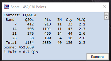
Well below is my score and I have to say that before the contest I had sugar plums dancing in my head with a high score but it turned out it was more like roasted chestnuts. Nothing wrong with that and I did have a blast.
