 Deteriorating ceramic filters due to DC
 |
| Tandberg Huldra 10 |
Tasos, SV8YM, has written about “The Mysterious Case of the Withering Filters“. This seems to affect not only ham radio transceivers, but FM stereo receivers as well.
Tandberg from the 70’s are collectors items and since I actually worked one summer at Tandberg in the early 70’s they bring back good memories for me. The latest generation of receivers (2nd version of Huldra 10, Huldra 11, and Huldra 12) had ceramic filters for the 10.7 MHz intermediate frequency for FM. It is also known that these filters deteriorate leading to reduced sensitivity over time.
SV8YM has pointed out that ceramic filters deteriorate due to DC on the terminals, especially the output terminal and that this leads to electromigration. In the Huldra 10, both filters have 7.1 V DC on the input. Filter F1 has 0 V DC on the output, while F2 has 2.1 V on the output.
| Old filters (left) and new filters |
As I got ready to replace mine with new Murata filters (SFELF10M7GA00-B0, 230 kHz bandwidth), I read the same warning in their specifications, which says: “For safety purposes, connect the output of filters to the IF amplifier through a D.C. blocking capacitor. Avoid applying a direct current to the output of ceramic filters.“
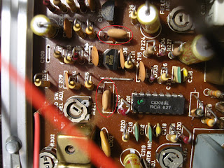
I also noticed that the filters had been replaced before. To be sure, I added three coupling capacitors (10 nF – 0.01 uF). This value has a reactance of 1/(2 pi 10.7e6 0.01 e-6) = 1.5 ohms which is negligible compared to the 330 ohm termination impedance. They were surface mount capacitors which is quite some upgrade as they perhaps were not even invented when this receiver was designed. They were fitted under the PCB by cutting the appropriate trace. Whether this has any long-term effect I don’t know, as the Huldra 10 at the age of 40 years is beyond its design life anyway.
My somewhat inaccurate oscilloscope measurements indicated that the passband attenuation in F1 was reduced from 7 to 4 dB and in F2 from 9 to 2 dB, in total maybe as much as 10 dB gain. FM sensitivity seems to have been restored to normal value after this replacement, so it was well worth the effort.
 |
| The three new 10 nF coupling capacitors, circled in red |
 |
| The two filters, circled in red |


Back in the ’70’s, when I was repairing CB radios for my employer, I ran into a Craig CB that the passband of the ceramic filter had shifted to the “crack” between the channels – very “spitty” sounding audio. Maybe the end filter elements drift off frequency with dc voltage applied for an extended period.
Good point, could very well be
In the 1960s when I built my 1st SSB exciter I was playing around with some Mechanical filters—some were Collins & the others were relatively new–they were Japanese Kokusai filters—–there was always a warning –never impose DC voltages directly on the input & output terminals—-also never ever a negative DC potential on them.
I guess ceramic filters also have a similar problem—-I used small isolating IF kind transformers–they provided matching & also less gain loss compared to just an isolating capacitor.