 FreeTrak progress
I have made some progress with the FreeTrak PIC based APRS tracker. I found a slightly newer version of the PICFlash programming software. At first this gave exactly the same warning message as the original version. But after a bit of random clicking I tried again and this time the software reported that it was writing to the chip. It verified OK as well. I don’t know exactly what I did, but at least that hurdle was now passed.
 |
| FreeTrak configuration |
I set the DIP switches on the EasyPIC board to link the PIC pins used for serial I/O to the serial output. That didn’t seem to work the first time, either, but at the second attempt at powering up I saw the configuration prompt appear in the terminal window. I was able to complete the FreeTrak configuration with the PIC in the development board.
Next, I changed a DIP switch to put the chip in Run mode. Using a utility called NMEAGen I began sending simulated GPS messages to it using the same serial connection I used for configuration. The LED began flashing at 1 second intervals and using a crystal earpiece on the output pin I could hear the familiar sound of 1200baud packet bursts. I don’t know why it appears to be transmitting at 1 second intervals, but perhaps it is something to do with the simulated GPS data.
 |
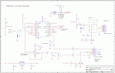
| FreeTrak schematic |
So FreeTrak appears to be working. All I need to do now is build it on to a circuit board and attach it to my GPS module and a radio. Here’s where I could use a little help from readers. The AFSK audio output of the FreeTrak uses an obsolete op-amp which is unobtainable. I presume I could just replace this with a simple transistor amplifier stage using a 2N3904 or similar, but do I really need anything at all, given that the audio will drive a sensitive microphone input? Could I get away with just a DC blocking capacitor and a trimpot to set the level?
The other thing I’m unsure about is how to interface the FreeTrak to my GPS module. I think the circuit shown is intended to work with GPS devices that use 5V TTL or even RS-232 signal levels. The data sheet for my bare GPS module states quite clearly that the absolute maximum voltage on any of the pins is 3.3V. The serial lines on the PIC measure close to 5V. How to connect them?


The op-amp is a buffer… the LPF to the Mic is after the opamp. You could redesign that in many different ways, but a single ended Class-A NPN amp wouldn’t be my first choice. If you really don’t want to worry about it, substitute ANY single-ended rail to rail op-amp part and you should be good.
You don’t need the amplification (it’s a unity gain circuit) but the buffering is such a good idea for so many reasons.
I’d recommend a suitable op-amp, but the ones I know of, I’d have to look up if DIP packages are available, and then further verify that a UK supplier stocks them. Off the top of my head, TI, ON Semi and Analog make suitable parts for around $.80 here in the States.
Worst case, you could use a standard 741 type op-amp by creating a virtual ground (including to the radio, remember) with a resistive divider (divide by two) and in something this simple it would work, but you’d want to power that from 12V (and the PIC with 5V).
Good Luck.. that’s a cool project. I have an OpenTracker from Argent that I bought at Dayton and assembled in my hotel room and used all the way back home. The kids thought it was super cool.
Fred W0FMS