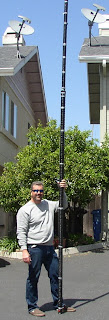
 K6MM’s 160m No Excuses Vertical
 Photograph One illustrates completion of vertical section(s) one and two. I worked my lower back while winding but I’m confident the helical wind itself met my exacting standards. Duct tape used to secure every twelfth or so winding. My plan is glue the helical wind after field testing and final standing wave measurements are taken.
Photograph two taken of third man or a pair of vice grips used to secure first section wire splice. We discussed the wire splice illustration in the ARRL’s Antenna Handbook and concluded its six inch requirement with twist is best for dipole-like tensions. I scraped enamel coating from each AWG #14 solid core wire prior to soldering.
Photograph three depicts section one and two layout after completion of winding using a spool as illustrated in photograph two. The spool facilitated downward and upward motion creating enough necessary tension to wind antenna wire.
Photograph four captures approximate 1/2 inch winds thus far consuming 201 feet of copper wire between first and second sections.
Photograph five taken of a pair of slugs used to connect both sections. I opted for this type of connection as mechanically sound versus alligator clips given the potential for lateral motion. I’m constructing the antenna as a portable type rather than fixed. However I might be corrected on connection terms because I simply forgot after leaving the hardware store.
Remaining Project Objectives.
Section one is 45 percent complete and we’re fast approaching capacitance hat construction in the near future. Likewise, we’re discussing type of feed line for example, coaxial or window line as suggested in K6MM’s instructions. Furthermore, I’m brainstorming how-to fit 1/4 wave radials into the lot in the backyard, any suggestions?
73 from the shack relaxation zone.
P.S. Read K3LR’s method of installing a PL259 connector with photographs (link).


