 |
 ICQ Podcast Episode 288 – Amateur Radio Author Don Keith (N4KC)
In this episode, Martin M1MRB is joined by Leslie Butterfield G0CIB, Edmund Spicer M0MNG, Bill Barnes N3JIX and Ed Durrant DD5LP to discuss the latest Amateur / Ham Radio news. Colin M6BOY rounds up the news in brief and this episode’s feature is an interview by Frank Howell (K4FMH) with Amateur Radio Author Don Keith (N4KC)
ICQ AMATEUR/HAM RADIO PODCAST DONORS
We would like to thank Richard Boley and Dino Papas (KL0S) along with our monthly and annual subscription donors for keeping the podcast advert free. To donate, please visit - http://www.icqpodcast.com/donate
- Cricket World Cup Amateur Radio Marathon
- Comments Wanted on Amateur Radio Related Petition for Rule Making
- Radio Hams Transfer Crypto Currency on 40m Band
- Golden Globe Sailing Race - Penalty Given for Ham Radio Use
- Carole Perry (WB2MGP) is First Recipient of Award Named in Her Honor
- Tate Gallery Features Ham Radio Art
- St Patrick’s Day Special Events Station GB1SPD
- VeroRoute
- Highest Ever SOTA Activation
Colin Butler, M6BOY, is the host of the ICQ Podcast, a weekly radio show about Amateur Radio. Contact him at [email protected].
SDR, ham radio satellites, and antennas over amplifiers
 Stories you’ll find in our July, 2018 issue:
TSM Guide to Monitoring Air Shows
By Larry Van Horn N5FPW
Every year from March through November, millions of people hit the road to watch the excitement and thrills as military and civilian aero teams put their high-performance aircraft through their paces to entertain the crowds and perform at air shows all over the world.But you can add to the experience by monitoring the performing teams’ radio communications. With a radio scanner in hand, you will experience a whole new perspective of the show that few attendees will experience. Larry lets us all in on the frequencies used by all participants in these shows in VHF and UHF civilian and military bands.
A Look Back at the 2018 Air Shows
By Brian and Jo Marie Topolski
Air shows offer a variety of aerial action and every year is a little bit different. Veteran air show attendees, Brian and Jo Marie, give us a look ahead at the 2019 season and a look back at what happened last year. Among the new teams to look for this year are the Royal Air Force aerobatic jet team known as the Red Arrows and the US Department of Defense F-35A Lightning II demonstration team. Brian and Jo Marie tell you where you are likely to hear communications from these teams as well as all of the others. The duo also takes a look back at the losses that occurred during last year’s air show season.
Photos from 2018:
B-52 Stratofortress; Japanese Navy Type 97; Mitchell B-25
By Brian and Jo Marie Topolski
It’s hard not to be attracted to the impressive sight of a Blue Angels or Thunderbirds aerial demonstration. The number of planes in the air at once, the deafening sound of their pass across air show center are thrilling. But there are plenty of quality side shows as well. Brian looks closely at several examples of vintage aircraft and the role they played in aviation history.
In the Air for Sean D. Tucker’s Last Solo Season
By Kevin Burke
The dramatic photo on the front cover was taken by Kevin Burke, who has had the opportunity several times to fly in a chase plane following the daring aerial exploits of veteran air show pilot, Sean D. Tucker. It’s not an easy assignment and to get this kind of photo you need to have a good camera, plenty of experience using it and an ability to forget that you’re being held into the plane by a belt during a flight nearly as breathtaking as Sean’s.
Photographing USAF Thunderbirds’ Air Show Demonstration
By Kevin Burke
When you go to an air show, you’ll want to bring along your camera to try to freeze some of the drama for later viewing. But, there’s a trick to photographing moving objects, particularly when they’re moving at hundreds of miles per hour, at heights anywhere from 200 feet to 5,000 feet, under rapidly changing light conditions. Kevin has had a lot of experience doing so and has some tips for your next air show.
Scanning America
By Dan Veeneman
Scanning Jackson County, Mississippi
Federal Wavelengths
By Chris Parris
Atlanta Federal Mysteries and Super Bowl 53
MilCom
By Larry Van Horn N5FPW
Monitoring Venezuela’s Military
Utility Planet
By Hugh Stegman
Rejoice! WWV is Saved!
Shortwave Utility Logs
By Mike Chace-Ortiz and Hugh Stegman
VHF and Above
By Joe Lynch N6CL
ESA Astronaut Tim Peake KG5BVI and
UK Space Agency’s Principia Education Campaign
Digitally Speaking
By Cory GB Sickles WA3UVV
EMCOMM and DV Radio
Amateur Radio Insights
By Kirk Kleinschmidt NT0Z
Antennas before Amplifiers
Radio 101
By Ken Reitz KS4ZR
OTA-TV and the Mystery of HDMI
Radio Propagation
By Tomas Hood NW7US
It’s a Gray Area
The World of Shortwave Listening
By Ken Reitz KS4ZR
Shortwave Listening in the 21stCentury
The Shortwave Listener
By Fred Waterer
Shortwave Still Offers Exotic Listening
Amateur Radio Satellites
By Keith Baker KB1SF/VA3KSF
Amateur Radio Satellite Primer (Part III)
The Longwave Zone
By Kevin O’Hern Carey WB2QMY
Still Learning with SDRs!
Adventures in Radio Restoration
By Rich Post KB8TAD
James Millen and the Toy Company
Antenna Connections
Dan Farber AC0LW
Flying High Again: Aircraft Antennas
The Spectrum Monitor is available in PDF format which can be read on any desktop, laptop, iPad®, Kindle® Fire, or other device capable of opening a PDF file. Annual subscription is $24. Individual monthly issues are available for $3 each.
Ken Reitz, KS4ZR, is publisher and managing editor of The Spectrum Monitor. Contact him at [email protected].
Amateur Radio Weekly – Issue 231

Reduce HF noise with Faraday Cage for switching power supplies
The results are very promising with the shielded supply eliminating the noise almost entirely.
rtl-sdr.com
“RF Seismograph” may be real seismograph
Alex Schwarz, VE7DXW, in British Columbia, Canada, is exploring the possibility that “RF signatures” detected by the RF Seismograph propagation tool could also be indicating earthquakes, and may even be able to predict them shortly before they occur.
ARRL
FreeDV QSO Party 2019
April 27th 0300z to April 28th 0300z 2019. This is a great chance to try out FreeDV and work Australia using open source HF digital voice.
Rowetel
Does WiFi kill houseplants?
Spoiler alert: No. To come to that conclusion, Andrew McNeil ran a pretty neat little experiment.
Hack A Day
Ultimate crimp guide with photos
Common wire-to-board, wire-to-wire connectors, and crimp tools.
Matt’s Tech Pages
In-depth: Ham Antarctic expedition
Between January 14 and February 18 I have been away from home on a research expedition to Antarctica. Several people have asked me for a post detailing my experiences.
Daniel Estévez
WiFi RF as art
The installation represents four open Wi-Fi Internet access points. By connecting to these points, visitors to the exhibition influence directly, through their network activity, a rhythmic sound generation process.
vtol
Ailunce HD1 Codeplug
If you are like me and just want to use your HD1 with a Jumbo Spot (or any hotspot) this is the easiest codeplug you’ll ever find.
K0PIR
LTE on Ham Bands in Austria
The goal is to use SDR and OpenLTE software to develop fast data transfer from 70cm upwards.
Southgate
Video
How to decode POCSAG & FLEX using an RTL-SDR Dongle
How to decode POCSAG & FLEX pager messages.
M6LME
Explained: The first geostationary satellite for Ham Radio
We take a look at the Ham Radio transponders of the new Es’Hail 2 Satellite.
Tech Minds
Get Amateur Radio Weekly in your inbox.
Sign-up here
Amateur Radio Weekly is curated by Cale Mooth K4HCK. Sign up free to receive ham radio's most relevant news, projects, technology and events by e-mail each week at http://www.hamweekly.com.
Ham Radio Exam – Tech Study App Review
If you know someone who is planning on getting their ham radio license, this app may be just what they need.
It was written by Roy Watson, N1ZTL and has the current question pool (2018-2022). The app has 67 reviews on iTunes and boasts a 4.8 star rating — and it’s also free.
You can study each question in the question pool and each section is broken down by the number of questions per section as well.
Once you select a section, it gives you each question number, the text of the question and the four possible answers as well with the correct answer highlighted in green.
If you’re interested, check out my full review of this app.
73 y’all
Curtis Mohr, K5CLM, is the author/owner of Everything Ham Radio Blog and Youtube channel. Contact him at [email protected].
T1D Toys
Lets start this with a clear statement – This is not a ham radio post 
Introduction
My youngest was diagnosed with Type 1 diabetes a little over 12 months ago. Type 1 is a bit different from Type 2 diabetes in that it is auto immune and there is no insulin available. This means a regular tightrope of carbohydrate intake and insulin being administered. In our case this is through a pump.
In the good old days that meant taking a bit of blood from your finger. measuring it for blood glucose and then acting on the information. This could mean correcting to meet a magic number (6 mmol) or just before a meal.
In the modern connected world there are a few toys that can help you. Freestyle Libre continuous glucose monitoring, Nightscout, XDrip+, Miao Miao, Smart watches…….This is my experience of setting a few of these things up. Hopefully in a non techie way.
Setup prior to new toys
- Omnipod Insulin delivery with the Insulet PDM
- Old android phone
- Freestyle Libre Continuous Glucose Monitor (CGM)
The game goes like this. Offer up your phone to your patch, it reads the sensor and you get a BG reading on your phone. Make any adjustments using the PDM Nothing too exciting there.
The problem
The problem with this is that at night there is still a regime of checking. The CGM is collecting data and it needs a human to wave a phone near an arm (invariably the wrong one, in fact sometimes it takes three goes to get the correct arm!)
There are no alarms or warnings
After a few poor nights of sleep it is easy to miss a check and hence mistakes will happen
A solution
Here’s the basic wish list. Use the CGM to it’s potential without waiting for a commercial integrated solution. This means connecting a few things together and for the information to be displayed on a smartwatch in such way that it provides an adequate indication of the state of BG play. So here are the ingredients
- Freestyle Libre – The CGM
- Miao Miao – A bluetooth device that sits on the Libre patch
- Android Phone – The hardware glue
- Fitbit Verso – A reasonably priced smart watch
- xDrip+ – Software glue
- Glance – A watch face to display the info
The system works by the Libre monitors the BG, The Miao Miao collects the data every 5 minutes, xDrip+ receives the data and manipulates it and lastly the Verso shows you whats going on. All this because there isn’t a straightforward off the shelf solution (yet).
What I want is this….


Steps
First thing to remind yourself is that this is not a medical device or set of devices. This is the equivalent of bleeding edge homebrew, short only of a step that makes the adjustments for you.
You’ll need a bit of time – A good hour or two depending on your skills
Set up the FitBit
This bit should be relatively straightforward. Download the App, sign your life away to megacorp and do the updates it prompts for. This took about 30 minutes and to be honest wasn’t smooth. The software could be a bit better but eventually it works. At the end of all this you should have a working FitBit with the default screen.
Set up the Miao Miao and xDrip+
Luckily for me there is a good guide on the Miao Miao website so as long as you can follow that you should be ok. As this stuff is a bit techie it assumes you understand what repositories are and installing apks from sources other than Google Play for example. It’s not as hard as you might think and if you struggle here’s one of few thousand tutorials.
At the end of this you should have a phone that is collecting data every 5 minutes from the Libre patch and giving you a pretty picture. An optional step would be to add a follower to xDrip+. This might be handy if like me you are a parent and you’ll effectively mirror the data on your phone as well as the kids phone. The developers have done a nice video that will show you what to do.
Next up – displaying the information on your FitBit
Again, all the hard work is done for you. Using the phone you used to install xDrip+ and connect to the FitBit and navigate to this page on a browser. There is a good wiki but there are basically two steps to this.
Change some settings in xDrip+
Changing the settings allows the xDrip+ software to send the information to the watch but it is easy. Go to settings, then InterApp settings, then xDrip Web Service. Change this to on
Add a ‘Watch Face’ to the FitBit
The wiki gives you a warning about making sure you’ve done the first step. Make sure you do this. Follow the link to ‘Latest version of Glance’. This will open up the FitBit app and after some time will install the watch face.
Some problems I found
- You need to make sure the Miao Miao is well and truly stuck to the Libre patch. Even a mm is enough for it to not connect.
- The xDrip+ software is really very capable. A slip with the fingers and a wrong setting will stop it working. For example a FitBit verso is not an Android watch. Take care when setting things up.
- This is a do it yourself system and there are a whole bunch of people that can help, but it moves from plain English to TechSpeak pretty quickly and can look daunting. It need not be like this.
Alex Hill, G7KSE, is a regular contributor to AmateurRadio.com and writes from Cumbria, UK. Contact him at [email protected].
The 2019 Novice Rig Roundup (NRR)
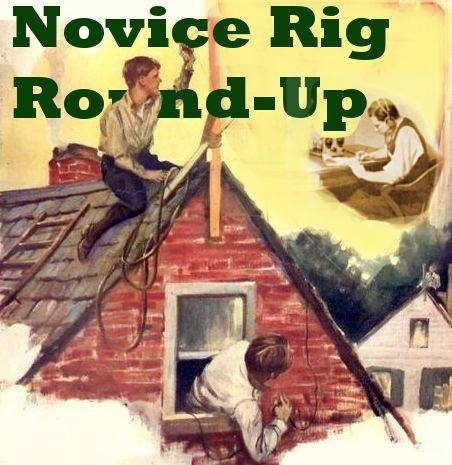
One of the most enjoyable operating events of the year is fast approaching — the Novice Rig Roundup or ‘NRR‘. Technically, it is a contest, but I have the feeling that most participants think of it as just a lot of fun and a nice opportunity to hear and work some of the great old ‘classics’ of the past — rigs that were used when they were teenage Novices or rigs that they could only drool about owning, back in those formative years when they each discovered the magic of radio.
Once again the bands will be alive with the sounds of Heath AT-1s, DX-20s, DX-35s, DX-40s and DX-60s, Johnson Adventurers, Eico 720s, Drake 2NTs, Knight T-50s and T-60s, Ameco AC-1s and of course, an endless variety of lovingly-constructed homebrew delights and … a full 9 days to celebrate the ‘good old radio days’ of their teen years, as many of us remember them.
The dates to remember are 0000 UTC March 2 to 2359 UTC March 10 and this multi-day opportunity is, for me, what makes the NRR so enjoyable. With a nice diversion from the usual ‘contest frenzy’ associated with standard weekend operating events, the NRR can be enjoyed throughout the week, whenever you choose to participate. If last year’s operating patterns continue, you should find activity at any time of the day … and even more as sunset arrives.
With the fast-approaching solar minimum, we will be hard-pressed to relive the glory days of worldwide 15m propagation, as even last year’s event proved to be tough on this band. With a little luck and, hopefully, a well-timed solar flare, we may get lucky! If you operate during the daylight hours, please get on 15m and give it a shot … and be sure to announce your activity on the NRR’s sked and chat page here, so that others will know where to find you, especially if you are rock bound in true Novice fashion. With our present spotty conditions, we need all the help we can get and the sked page proved a very valuable asset during last year’s affair.
Although technically not required, if you plan to participate it’s best to obtain your own NRR number, which is an easy 30-second process.
Additionally, there is an online logger where participants can post their daily log. The nifty logger also keeps track and figures out your score as it goes and no ‘after contest’ log needs to be submitted. If you plan on submitting a log, the logger is a requirement. The logger will also require you to set up a ‘log-in’ and once again, a simple 30-second process will take care of that from here. If you used the logger last year, you will have to set it up again for this year as the old system has been changed.

Stations may run either crystal-control or VFO or can switch between either method … the online logger will keep track and score things appropriately.
All of the rules and information can be found on the NRR’s excellent website. As well, the soapbox comments and station pictures from last year’s NRR may provide the inspiration that you need to spark-up your own activity in this year’s event … from what I can tell, this year will be bigger and busier than ever!
There is also a dedicated NRR Yahoo Group, often the source of much valuable discussion but there is a now HUGE group of great NRR chat and activity now on Facebook’s NRR Group here. I avoided Facebook for many years and have now discovered that it is an excellent forum for real time chat and information exchange … one can still choose to maintain a very low profile and avoid unwanted interaction if set up correctly.
In 2017 I ran my homebrew Longfeller in the (now eliminated) QRP category, and had a ton of fun. You can read about it here. Last year, I refurbished a nice Drake 2NT that had been gathering dust in the basement for over 25 years and ran it during the 2018 NRR. You can read about my activity and some of the rigs encountered during last year’s fun here.
If you have access to the web while operating, be sure to bookmark and check into the NRR’s realtime chat page. Many ops that are crystal controlled will announce their operating frequencies, making it easier for you to find them … sometimes way up or down from the normal NRR watering holes of ~ 3550 – 3650 kHz, 7100 -7125 kHz, 21.100 – 21.150 MHz and 28.114, 28.120 MHz … and don’t forget to check the colorburst crystal frequency of 3579!
‘CQ’ers should always remember to tune up and down the watering hole for replies from other NRR stations that may be crystal controlled and not able to answer you on your own frequency!! This is extremely important and a real reminder of what was common practice back in the Novice days.
 |
| courtesy: Harry – VE7AIJ |
Harry’s homebrew 6AQ5 crystal oscillator (Feb ’55 Popular Electronics) and Hallicrafters S-53, pictured above, allowed him to work the world back in the amazing radio days of Cycle 19. Let’s relive some of that excitement in the closing days of Cycle 24 … in the NRR!
You still have time to get that old clunker on the air but if that’s not possible, you can join the fun with your modern rig as well … all are welcome to jump in and have a great week of radio-fun. I think you will be surprised, just as I was last year, how good some of these old classics can sound … and you’ll hear some great bug-fists as well.
As indicated on the NRR website, this is “more of an EVENT than just a typical contest … once again taking our OLD ham radios off the shelf and putting them to use again! “
See you in the 2019 NRR!
Steve McDonald, VE7SL, is a regular contributor to AmateurRadio.com and writes from British Columbia, Canada. Contact him at [email protected].
LHS Episode #273: DX Cluster and Spotting Deep Dive
Thank you for tuning into the latest episode of Linux in the Ham Shack. In Episode 273, the hosts take a deep dive into DX cluster applications and spotting techniques for finding those elusive amateur radio contacts. From desktop and mobile apps to networked nodes and server libraries as well as spotting techniques, no stone is left unturned.
Best 73 and DX from the LHS Crew
Russ Woodman, K5TUX, co-hosts the Linux in the Ham Shack podcast which is available for download in both MP3 and OGG audio format. Contact him at [email protected].
 Ham Radio Deluxe |
 W5SWL Electronics |
 Ham Radio Prep |
 KB3IFH QSL Cards  Hip Ham Shirts  HamRadioAuctions HamRadioAuctions Reliance Antennas Reliance Antennas Enigma Shop Enigma Shop |  morseDX  Ni4L Antennas  R&L Electronics R&L Electronics antennas.us antennas.us Ears to Our World Ears to Our World |
- Matt W1MST, Managing Editor
