 |
 Amateur Radio Weekly – Issue 215

FT8 QSO Mode
No character type restrictions, 23 characters per 15 second transmit period.
KN4CRD
ARRL annual report highlights membership problems
Membership is forecast to continue to decline in 2018 (2% loss is forecast).
KB6NU
New FCC Part 95 rules
Additional FRS channels and increased power on certain FRS channels from 0.5 W to 2 W.
ARRL
AREDN mesh network progress
We have been working on bringing up an AREDN mesh network at ARRL HQ and here at AA6E.
AA6E
Nunavut operation
Active from Iqaluit, Nunavut as VY0BRR using all modes and all bands except 160.
Southgate
How much battery do you really need?
There are some basic battery concepts that will help you sort through this confusing topic.
Off Grid Ham
Breaking ground
With building permit in hand, it’s finally time to get my vertical… vertical again!
W0EA
SDR-Remote: A physical tuning and control knob for SDR#
This is a physical tuning knob that connects to your PC, and can be used with programs like SDR#.
RTL-SDR.com
Screwdriver antenna experiences
Even on a compact SUV.
Surrey Amateur Radio Club
Video
More on the J-pole Antenna
A close look at how the J-pole antenna works with special attention to how it’s fed.
David Casler
How to decode 433Mhz low power devices
Here we take a look at decoding some of the micro transmissions from Low Power Devices on the 433Mhz band using RTL433 software for Linux and Windows.
Tech Minds
Get Amateur Radio Weekly in your inbox.
Sign-up here
Amateur Radio Weekly is curated by Cale Mooth K4HCK. Sign up free to receive ham radio's most relevant news, projects, technology and events by e-mail each week at http://www.hamweekly.com.
AmateurLogic 120: Raspberry Pi for PC & Mac
AmateurLogic.TV Episode 120 is now available for download.
George installs Raspberry Pi Desktop for PC and Mac.
Tommy visits John Amodeo on the new set of Tim Allen’s Last Man Standing. Watch it come together.
Emile shows the long awaited, multifunction, PiClock.
October will be ALTV’s 13th Anniversary. We are celebrating with another contest. Get all the details here.
1:21:16
George Thomas, W5JDX, is co-host of AmateurLogic.TV, an original amateur radio video program hosted by George Thomas (W5JDX), Tommy Martin (N5ZNO), Peter Berrett (VK3PB), and Emile Diodene (KE5QKR). Contact him at george@amateurlogic.tv.
MiniTiouner DATV Receiver built
The build was straightforward and there are some instructions by Mike G0MJW but only really referenced them for the commissioning stage, checking voltages etc. I was pleasantly surprised to see a large degree of protection on the board, fuses both filament and poly-fuse, reverse protection and zener diodes in the circuit.
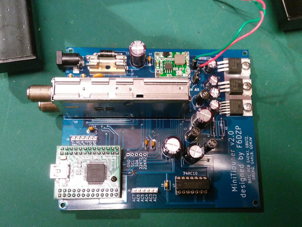
The MiniTiouner uses free to download DVB-S receive and analysis software called "Minitioune" written by F6DZP. The Software is hosted on the VivaDATV forum. So I registered and downloaded the software.
V8.0 of the software requires a pull-down resistor adding to the USB module to identify the type of board, so that was added (not pictured).
Power was connected and then plugged the USB lead into the PC (Windows 7 32bit) and it went off and installed drivers. The documentation said I should see two USB controllers, but I was seeing four?
There are several test programs included in the software package to test drivers and board and they were showing errors.
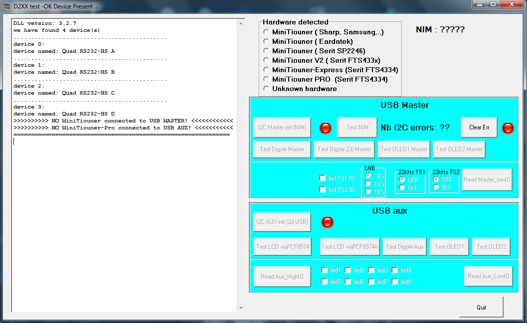

The PC I was using has had no end of serial USB devices plugged in and out over time so suspecting another Microsoft Windows "disappearing up its own backside" driver issue I tried it on another more vanilla machine but had the same problem.
This seemed to point to the USB interface (an FTDI FT2232H Mini Module) perhaps it wasn't programmed? So I downloaded the FTProg utility from FTDI but instead of seeing a FT2232H was showing it as a FT4232H device.
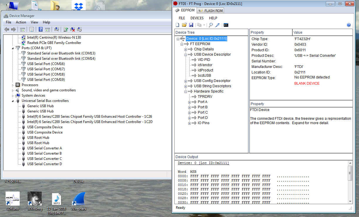
Doing a Google found a reference to the same problem. I downloaded the data-sheet and checking with a meter I could see pins CN2-5 and CN2-11(VIO) on the module didn't have 3.3V for some reason and as the post said if the VIO pin is missing 3.3V it defaults to a FT4232H. In the end I checked my soldering (no fault found) I removed the module from the socket to examine it and after re-seating it the board sprang to life so seems it was just a bad connection.
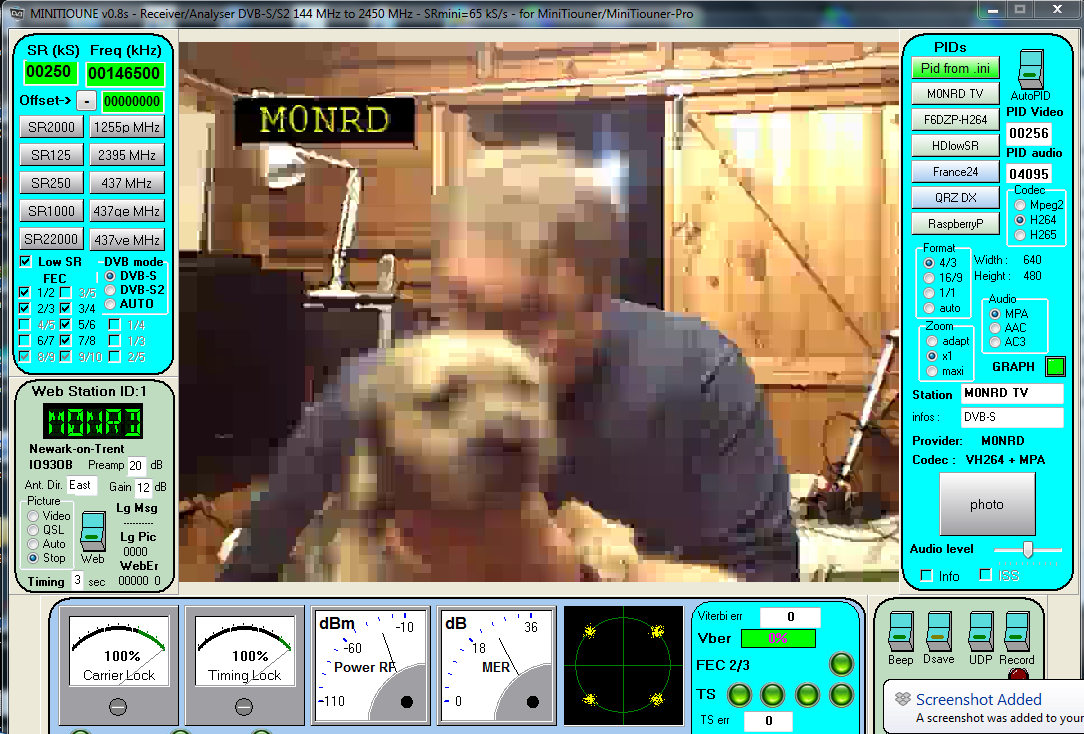
Eager to test I set up the ADALM-PLUTO SDR running DATVExpress as I'd done previously with the commercial set-top satellite receiver and we had a picture! It was time for a cup of tea!

Now it was working all that was left was to put it in a box.

I have only had a brief play with the software since the weekend but was interested to see if I could receive some RB-TV (Reduced bandwidth) So I set the Pluto and DATVExpress to transmit on 146.500MHz using a low symbol rate (250 Ksymbols/s) and it worked! Bertie was wriggling a bit too much for a clear picture but I had now actually used my 146-147MHz NoV. Now just got to learn and understand the various modulations and settings.
I was able to try out another piece of software, the Spectrum Analyser from Steve Andrew for the SDRPlay. It turns the SDR receiver into a handy spectrum analyser with 10MHz bandwidth from 1kHz upto 2GHz and was able to check the output of the Pluto.
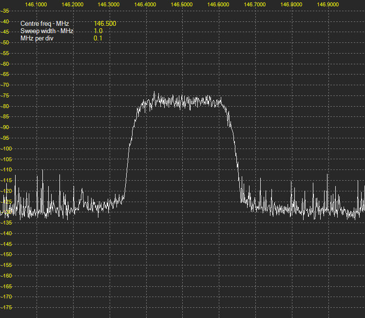
This wasn't a proper test setup by any means, the SDRPlay was still connected to the dual-band collinear outside the shack so the noise is the usual hash I see, but the Pluto was putting out a decent waveform, it did help putting on a proper resonant antenna (a spare mobile magmount) rather than the tiny one supplied.
I plan to do a bit more with the 5.6GHz FPV stuff before the weekend having took delivery of some nice grid antennas and hope to get out to try a contact or some tests with members of SKARS 73
Andrew Garratt, MØNRD, is a regular contributor to AmateurRadio.com and writes from East Midlands, England. Contact him at nerdsville@gmail.com.
LHS Episode #241: The Dark Side of Open Source
 Welcome to Episode 241 of Linux in the Ham Shack. In this episode, the hosts discuss emcomm in Indonesia, the UN radio club, amateur radio license changes in Norway, open source software in automobiles and medical fields, becoming an APRS weather alert station an another dive into the Github bins. Thank you for listening! If you aren't supporting us yet, please consider clicking on the sponsored ads, picking up some merch or subscribing via Patreon. Every little bit helps us keep the show going.
73 de The LHS Crew
Russ Woodman, K5TUX, co-hosts the Linux in the Ham Shack podcast which is available for download in both MP3 and OGG audio format. Contact him at russ@bluecows.com.
Recent Noise Mystery Solved
Perhaps others can help explain something odd that I have just noticed with my Perseus while comparing antennas.
I was comparing signal levels and noise between a 40m half sloper and a very high dual 40/80m pair of inverted-V dipoles fed from a common feedline. Both the sloper and the dipoles are fed with 50 ohm cable and all three antennas are well matched at the low end of the band(s).
Listening to a 6 MHz signal from China National Radio around 10 am today, the signal was around S7-8 on the Perseus, using the 40m sloper. Listening to the same signal, at the same time, on the Yaesu FT-1000mp, with the high inverted-V, it was slightly better, maybe by 5-6 db and overall lower noise. I then put the inverted-V onto the Perseus and there was not even a trace of the signal! I made this check with several signals and always with the same result.
Now I suspect that the SWR of the 7MHz inverted-V when used at 6MHz, is very high and the load presented to the Perseus antenna input is likely highly reactive and far from 50 ohms but that doesn't seem to bother the FT-1000.
I then ran the inverted-V through my antenna tuner so that it effectively produced a 50 ohm non-reactive input load for the Perseus and did the tests again...with the same results. Swapping antennas for the 40m sloper once again produced the same signal levels in both the Perseus and the FT-1000.
So what is going on here and why does the Perseus balk at the 7 MHz inverted-V while listening on 6 MHz? Is there something in the Perseus front-end analog filtering system that is overly sensitive even though the reactance was tuned out via the tuner? Is it the 80m V on the same feedline as the 40m V that is causing some still unwanted reactance that is not tuned out with the tuner?
Any ideas what is happening here as it looks like I will not be able to use the inverted-V antennas on the Perseus for general SWL out-of-band listening for some, as yet unknown, reason.
As you can see, I was completely mystified by what I was hearing, or rather not hearing, and as it turned out, completely off the mark.
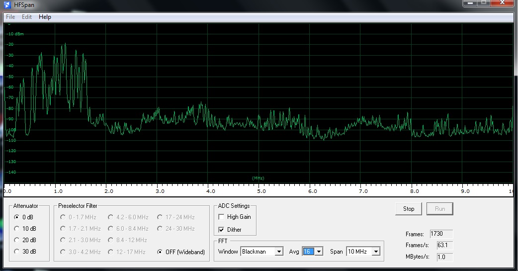
I received a few replies offering some possible reasons for what I was seeing but none of them proved helpful in solving my dilemma ... until Roelof Bakker (PAØRDT) weighed-in! Roelof suggested that I look at the antenna's performance while running Perseus's built-in 'HFSpan' function.
HFSpan is a stand-alone 0-40MHz spectrum analyzer, that comes with the Perseus software. Although I was aware of it, I have only used it sparingly. I next did some screen captures with all three antennas, one at a time, and sent them to Roelof.
His analysis did not take long as he immediately identified my problem ... a very high noise floor when using the mysteriously-performing inverted-V. Roelof suggested some common mode choking to eliminate the problem.
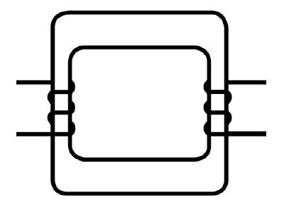
Already having an isolating transformer in hand from a previous experiment, I inserted it directly at the Perseus antenna input and looked at the noise floor again, around 40m. The transformer was wound on a small FT87-J core with a 3 turn primary directly opposite a 3 turn secondary. I was astounded to see the background noise floor drop from -85dbm to a very quiet -110dbm!
Evidently there was a lot of noise being picked-up on the inverted-V's feedline shield. Not hearing any of this noise on the FT-1000 indicated that the noise was probably associated with the Perseus power supply, the laptop or the laptop's power supply. This immediately explained why I wasn't hearing anything with this antenna when used with the Perseus.
Roelof then suggested that a 2 turn / 2 turn transformer, offering less inter-winding capacitive coupling, might provide even more isolation ... and he was right again. A further ~4dbm lowering of the ambient noise was measured.
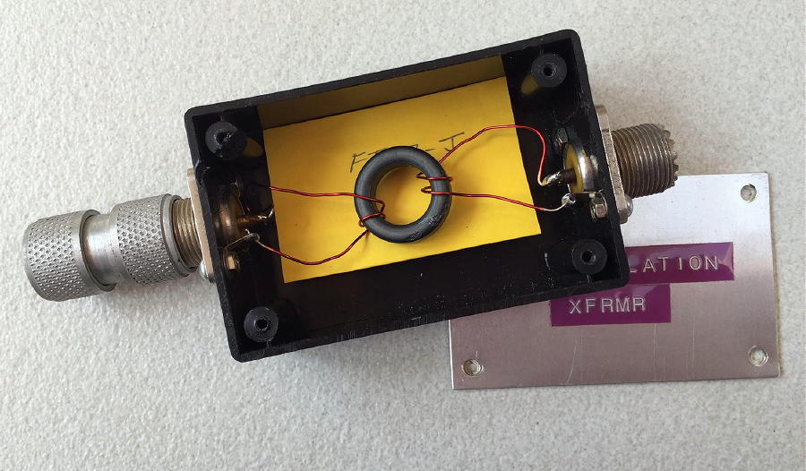 | ||
| It may not be pretty but it produced an astounding improvement! |
Further comparisons between the FT-1000 and the Perseus revealed that the FT-1000 was still producing a slightly better SNR than the Perseus, when using the inverted-V so evidently there was still some noise affecting the signal. I had a few very large #43 ferrite toroids and decided to wrap a few turns (5) of the RG8-X feedline around the toroid to see if there would be any improvement.
Once again, using HFSpan, I compared the noise floor both with and without the #43 choke and saw a further 6-7 dbm improvement! Going back to comparing SNRs between the FT-1000 and the Perseus, I now saw no difference between how I was hearing on both receivers, when using the troublesome inverted-V ... eureka!
 |
| 0-10MHz sweep - with noise problems |
 |
| Same sweep, noise eliminated, signals now unmasked |
As of yet, I have not determined the actual noise source. I suspected it may have been coming from the Perseus power supply or from the laptop supply but that was not the case. Perhaps it is coming from the laptop's processor via the USB cable which I will also choke and see if HFSpan reveals anything further
This problem was a great learning experience for me, in more ways than one and I am most grateful to Roelof for his detective work and experience with noise issues and for taking the time to respond to my initial inquiry. Hopefully you may find something here that can help you as well.
Steve McDonald, VE7SL, is a regular contributor to AmateurRadio.com and writes from British Columbia, Canada. Contact him at ve7sl@shaw.ca.
Pikes Peak SOTA: Hike from Devils Playground

I’ve been up Pikes Peak (W0C/FR-004) a zillion times via the Pikes Peak Highway and the Pikes Peak Cog Railway (currently out of service) doing SOTA activations, working VHF contests, participating in the Colorado 14er Event, maintaining repeaters and escorting visitors from out of town. See my previous post on activating by driving up the mountain: How To Do a SOTA Activation on Pikes Peak.
Joyce/K0JJW and I had Pikes on our SOTA activation list for 2018 but wanted to do a hike to access the summit. The classic climbing route up Pikes is via Barr Trail, a 13-mile trail that ascends 7800 vertical feet. This is a difficult climb for most humans but I will note that serious runners routinely run up the mountain just for fun. See Fred/KT5X’s comments on the SOTA database about running up the mountain and then doing a SOTA activation.
Another hiking alternative on the northwest side of Pikes Peak is the Crags Trail, also known as the Northwest Slopes route. This route starts about 4 miles south of Divide, CO at the Crags Campground. This hike is 7 miles one-way with 4300 vertical feet. This is easier than Barr Trail but still a significant climb.

Devils Playground
There is a shorter option that does not get much attention (except from some of the locals). The Northwest Slopes route crosses the Pikes Peak Highway at Mile 16 at a popular spot called Devils Playground. There is a large parking area there and the Northwest Slopes trail can be accessed at this point. Just cross the road, step over a cable fence (intended to block vehicles, not people) and follow the obvious trail to the summit.
Note: currently access to the summit by car is restricted due to summit house construction and Devils Playground is a staging area for free shuttle buses that take visitors to the summit.
This trail is 2.6 miles one way and 1300 feet vertical (mostly uphill but some up and down action). The last quarter mile before the summit is rocky and steep. The trail becomes more difficult to follow at this point but careful attention to the cairns will keep you on the right path. As shown on the map, this trail tends to stay close to the road so you will see vehicles along the way. All in all, this was a nice hike on a good trail.
Once on top, we set up our standard 2m FM station: Yaesu FT-90 and the Arrow 3-element yagi antenna. We quickly had a pileup on 146.52 MHz. It is kind of crazy up there when everyone starts calling because you are hearing everyone but the chasers are not.

It was great to work Steve/WG0AT on Mt Herman (W0C/FR-063) and Brad/WA6MM on Mount Morrison (W0C/FR-092). I also worked Paul/W0RW on 1.2 GHz with my Alinco HT driving a two-element yagi PC-board antenna. (A quick comparison between the rubber duck and the yagi confirmed that the yagi does have some gain.) We ended up in a bit of a hurry as the clouds moved in but tried to work everyone we could. Our best DX on 2m FM was Dave/N0KM near Del Norte, about 100 miles away. On our way down, the clouds were in and out but no storms or lightning.
All of the usual warnings apply for hiking above treeline: start early and get off the mountain before the storms move in.
73 Bob K0NR
The post Pikes Peak SOTA: Hike from Devils Playground appeared first on The KØNR Radio Site.
Bob Witte, KØNR, is a regular contributor to AmateurRadio.com and writes from Colorado, USA. Contact him at bob@k0nr.com.
Amateur Radio Weekly – Issue 214
All about Ham Radio
An introduction to the world of amateur radio.
SparkFun
JumboSpot DMR Hotspot
One of the latest crazes in the world of DMR radio is the Chinese iteration of the DMR hotspot. The principal attraction? Low cost. The Jumbospot costs about $45.
John Hagensieker
Light Up 2 Meters Night, an FM Simplex Event
August 26, 2018 7-9pm local time.
K5ACL
Radio hams at DEF CON 26
DEF CON 26 is taking place August 9-15 in Las Vegas and radio amateurs will be there giving presentations on HAARP, amateur satellite communications, and SDR’s.
Southgate
DIY vs. commercially made solar panel
The price of commercially made solar panels on eBay is around $1 per watt and have been for a few years, but the price of individual solar cells are likewise at a low price per watt, around $0.48.
Hack A Day
Receiving GOES weather satellite with a 2.4 GHz WiFi grid antenna
GOES 15/16/17 are geosynchronous weather satellites that beam back high resolution weather images and data.
RTL-SDR.com
Moving Pictures: First dabbles in Amateur TV
I’ve spent the last couple of weeks experimenting with some Amateur Television ATV and Digital ATV.
AmateurRadio.com
Wisconsin residents embrace Amateur Radio
An estimated 2 million people are on the airways worldwide, according to the American Radio Relay League. About 830,000 amateur radio stations are located across North, Central, and South America alone.
U.S. News
A primer on grounding for Hams
Nothing like a fierce electrical storm to get Hams talking about susceptibility to lightning strikes. Well, we experienced just such a storm in early August, which provides the perfect opportunity to review the topic.
VE7SAR
Video
Building a multi-band HF dipole antenna
Here I build a multi-band dipole antenna for HF use on 40-20-15-10-6 meters. Some call this a fan dipole.
RadioHamGuy
Nashville Amateur Radio Club Field Day 2018
NARC Field Day 2018 at Lock 2 Park, Nashville, TN
K4CPO
Get Amateur Radio Weekly in your inbox.
Sign-up here
Amateur Radio Weekly is curated by Cale Mooth K4HCK. Sign up free to receive ham radio's most relevant news, projects, technology and events by e-mail each week at http://www.hamweekly.com.
 Ham Radio Deluxe |
 W5SWL Electronics |
 Ham Radio Prep |
 KB3IFH QSL Cards  Hip Ham Shirts  HamRadioAuctions HamRadioAuctions Reliance Antennas Reliance Antennas Enigma Shop Enigma Shop |  morseDX  Ni4L Antennas  R&L Electronics R&L Electronics antennas.us antennas.us Ears to Our World Ears to Our World |
- Matt W1MST, Managing Editor
