 uBITX professional case
The case comes predrilled, with the cut out of the panel for the frequency display, ready to house the uBITX PCB. This sure makes the uBITX look the part in the shack. Complete with all the missing fittings, speaker, knobs, USB, SO239, mic skt, etc (the full list of parts is on the website).
Shipping starts early March.
Link here for:
Universal Case DA Grey
Steve, G1KQH, is a regular contributor to AmateurRadio.com and writes from England. Contact him at g1kqh@arrl.net.
 Travel Footage: 3Y0Z Antarctic Bouvet Island DXpedition 2018 Expedition (by EY8MM)
Here is video footage of the journey to Antarctic Bouvet Island, made by the 3Y0Z amateur ham radio team. This footage caught a few moments on the deck of M/V Betanzos.
As you can see in the last moments of this footage, the weather conditions contributed to the decision to abort the DXpedition, as it was far too dangerous to continue this expedition.
As reported by ARRL:
“Our captain has decided that it is in the best interest of safety and expediency to proceed directly to Capetown, South Africa, rather than Punta Arenas, Chile. We are now heading north to avoid the possibility of encountering ice. Currently, there is no ice in sight or on radar. In due time, we will head easterly toward Capetown. Our entire team is safe. Most are resting in their bunks and in good spirits. We will keep the amateur radio community and our families informed, as we continue our journey.”
In a huge disappointment for the DX community and the members of the 3Y0Z Bouvet Island team, the DXpedition’s leaders announced at 2000 UTC today (February 3) that a decision had been made to abort the DXpedition and head back to Chile.
“During the last 72 hours, we continued to experience the high winds, low clouds, fog and rough seas that have prevented helicopter operations since our arrival at Bouvet,” said an announcement on the 3Y0Z Bouvet Island website. “No improvement was predicted in the weather forecast for the next 4 days. Then, last night, an issue developed in one of the ship’s engines. This morning, the captain of the vessel declared it unsafe to continue with our project and aborted the DXpedition. We are now on our long voyage back to Punta Arenas. As you might imagine, the team is deeply disappointed, but safe. There is already talk about rescheduling the DXpedition.”
Bouvet Island currently is the third most-wanted DXCC entity, behind Kosovo and North Korea. The 3Y0Z DXpedition, comprised of top operators with considerable DXpedition experience, has been in the planning stages for 2 years and had attracted contributions from clubs and individuals around the world.
A dependency of Norway, Bouvet is a subantarctic island in the South Atlantic. The last Bouvet activation was 3Y0E, during a scientific expedition over the winter of 2007-2008.
Video Author: Nodir Tursun Zade, EY8MM
This copy is used BY PERMISSION from EY8MM, given in writing on 23 February 2018
Visit, subscribe: NW7US Radio Communications and Propagation YouTube Channel
 Review – BTech AMP-25 series for Analog & DMR
The AMP-25 series VHF / UHF Amplifiers
The recently announced BTech Digital and Analog amplifier series puts a whole new spin on mobile operation. It performs more like a mobile than it does a power amp. The D series are true TDMA Tier2 DMR amplifiers.
Note: This review was done using an Anytone D868UV on both DMR and analog.
In the Box
Included with the 40W Mobile Amp are:
– Mounting Bracket
– 3′ Interface Control Cable (Kenwood K1 connectors)
– 3′ RF connect cable (SMA-M to SMA-F)
– Microphone and Hanger
– All necessary mounting hardware
– User Guide
General Description
– UHF or VHF Power Amplifier
– 2-6W > 20-40W Output
Modes of operation include:
| V25 U25 | V25D U25D |
| Analog (FM) C4FM (Fusion) P25 (Phase 1) NXDN IDAS dPMR MPT1327 | > DMR Tier II (TDMA) > P25 (Phase 2) Analog (FM) C4FM (Fusion) P25 (Phase 1) NXDN IDAS dPMR MPT1327 |
A Different type of Mobile Amplifier
I found these to be much more than a typical power amplifier. Although they can function as a simple ‘In and Out’ power amp, this is about as close to a full mobile as you can get. Although the driving  force was my DMR handheld sitting in my cup holder, the transmit audio was that of the included hand microphone and the receiver audio out was coming through the built in speaker driven by a four watt audio amplifier.
Transmit Power
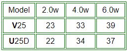
I tested the power on two different models. The VHF V25 (non TDMA) and the U25D for UHF DMR. The power was tested using the analog side of both into a calibrated Bird Termaline wattmeter. The maximum current drain from my 13.6V 30A power supply was just under 6A. This is low enough for the amp to be powered by the 10A accessory jack in your vehicle.
Enclosure
The basic frame measures 4.6″W x 1.3″H x 5.5″D (excluding the SO-239) and weighs in at 26oz. I was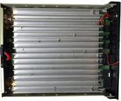 curious to see the internal layout of the amp and to no surprise, there was a 5/8″ finned heat sink spanning the entire length and width of the case along with air vent along the back of the enclosure.
Operating Modes
These are single band amplifiers.
V25(D) = VHF 136-174MHz
U25(D) = UHF 400-480MHz.
Note: The V25D and U25D were designed to include DMR Tier II (TDMA) and P25 Phase 2 along with all other modes. Their operation varies slightly.
V25 / U25
To operate VHF through the UHF (U25) amplifier, or UHF through the VHF (V25) amplifier, simply power off the amplifier. This will allow you to run straight through directly to the antenna without power amplification on that band.
V25D / U25D
These amplifiers will only operate within their specified VHF or UHF range. This is due to the circuit switching design of DMR Tier II and P25 Phase 2.
Hook Up
The simplest configuration is using the included RF cable to attach the radio to the amp. You could add a Spkr/Micr to the handheld, but you would still be bypassing some of the best features.
I use the two included cables. The 3′ RF cable to attach the radio to the amp, and the control cable. This allows me to use the full size hand microphone as well as connecting the four watt audio amp powering the speaker. The power included power cable is compatible with handhelds using the standard two pin Kenwood style connector, such as an MD380, D868, GD77, UV5R, F8HP, UV82, etc.
I use an Anytone D868 on DMR as well as analog with the hookup diagrammed below. Depending on your radios antenna jack, you may need to pickup an SMA-M to SMA-M adapter.
Convenience
All channel selection and volume adjustments are done using the handheld. No duplicate programming or code plugs are necessary. Whatever is in my handheld is what I operate in the mobile
Operating my handheld in the low power position, I still get 22W out on UHF and my handheld’s battery life remains excellent, but high power gives me a solid 39W.
Conclusion
I was glad to see someone finally develop what is a full featured mobile amplifier capable of DMR as well as all other modes including C4FM and D-Star that is small enough to mount in the car, boat, and on top of your computer. This amplifier is Part 90 certified and definitely worth considering.
Available from Amazon: V25 V25D U25 U25D
and ![]()

VHF /UHF
Digital / Analog
Mobile Power Amplifiers
![]()
![]()
Hans, PD0AC, is a regular contributor to AmateurRadio.com and writes from Almere, The Netherlands. Contact him at pd0ac@outlook.com.
 Weekly Propagation Summary – 2018 Feb 26 16:10 UTC
Here is this week’s space weather and geophysical report, issued 2018 Feb 26 0308 UTC.
Highlights of Solar and Geomagnetic Activity 19 – 25 February 2018
Solar activity was very low throughout the summary period. No active regions were observed on the visible disk. No Earth-directed CMEs were observed in available coronagraph imagery.
No proton events were observed at geosynchronous orbit.
The greater than 2 MeV electron flux at geosynchronous orbit reached high levels from 19-26 Feb. A peak flux of 13,500 pfu was observed on 19/2030 UTC.
Geomagnetic field activity ranged from quiet to G1 (Minor) storm levels due to multiple negative coronal hole onsets. Quiet to G1 (Minor) storm levels on 19 Feb were associated with peak wind speeds of just about 550 km/s from a negative polarity CH HSS. The geomagnetic response declined along with solar wind speeds with quiet to unsettled conditions observed on 20 Feb and quiet levels on 21 Feb . A subsequent enhancement in solar wind speeds from another negative polarity CH HSS increased geomagnetic field activity to quiet to active levels on 22 Feb, and further to quiet to G1 (minor) storm levels on 23 Feb, which were also associated with peak wind speeds around 550 km/s. Activity dropped to quiet to unsettled on 24 Feb and completely quiet by 25 Feb as effects from the CH HSS waned.
Forecast of Solar and Geomagnetic Activity 26 February – 24 March 2018
Solar activity is expected to be very low throughout the forecast period.
No proton events are expected at geosynchronous orbit.
The greater than 2 MeV electron flux at geosynchronous orbit is expected to be at high levels on 26-28 Feb and 18-24 Mar due to elevated wind speeds from multiple coronal holes. Moderate levels are anticipated on 15 Mar and the remainder of the forecast period is expected to be at normal levels.
Geomagnetic field activity is expected to reach G1 (Minor) geomagnetic storm levels on 26 Feb and 18 Mar. Active levels are expected on 14 Mar, 16-17 Mar, 21 Mar and 22 Mar. Unsettled levels are expected on 27 Feb, 15 Mar, and 23-24 Mar. Quiet conditions are expected for the remainder of the forecast period. All elevations in geomagnetic activity are anticipated due to multiple, recurrent CH HSSs.
Don’t forget to visit our live space weather and radio propagation web site, at: http://SunSpotWatch.com/
Live Aurora mapping is at http://aurora.sunspotwatch.com/
If you are on Twitter, please follow these two users: 1. https://Twitter.com/NW7US 2. https://Twitter.com/hfradiospacewx
Check out the stunning view of our Sun in action, as seen during the last five years with the Solar Dynamics Observatory (SDO): https://www.youtube.com/watch?v=zXN-MdoGM9g
= = = = =
BOOK SALE: Space Weather and Sun Science – get these from Amazon, and help us stay online!
NOTICE: When you buy this (or any item after starting with this link), you are helping us keep our SunSpotWatch.com and other resources “on the air” (up and running!). In other words, you are helping the entire community. So, check out this book:
Here is the link to Amazon: http://g.nw7us.us/fbssw-aSWSC
We’re on Facebook: http://NW7US.us/swhfr
Visit, subscribe: NW7US Radio Communications and Propagation YouTube Channel
 LHS Episode #212: SSTV Deep Dive
 In Episode #212 of Linux in the Ham Shack, the hosts take an in-depth look at the origins and operation of Slow-Scan Television (SSTV) and the Linux-native application QSSTV which allows radio amateurs to enjoy the wonder of sending and receiving still images via radio waves. Thank you for listening and stay tuned for a special episode on the use of the QSSTV picture editor which aids in the generation of SSTV images.
73 de The LHS Crew
Russ Woodman, K5TUX, co-hosts the Linux in the Ham Shack podcast which is available for download in both MP3 and OGG audio format. Contact him at russ@bluecows.com.
 Ham College 38
Ham College episode 38 is now available for download.
General Amateur Radio Exam questions part 9. Digital Modes pt 1, Grounding.
54:03
George Thomas, W5JDX, is co-host of AmateurLogic.TV, an original amateur radio video program hosted by George Thomas (W5JDX), Tommy Martin (N5ZNO), Peter Berrett (VK3PB), and Emile Diodene (KE5QKR). Contact him at george@amateurlogic.tv.
 Voltage regulation, tube style
High voltage indeed
 |
| OA2 tube |
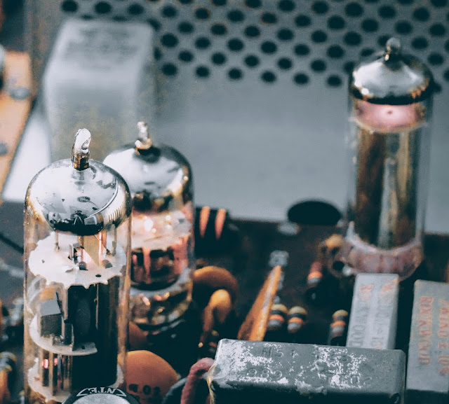 |
| OA2 in action at the right rear of the Audio board, notice the glowing gas inside |
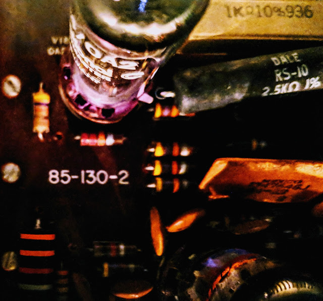 |
| Look at the pretty violet glowing gas in the OA2 |
The OA 2 is actually not a vacuum tube it contains a gas that ionizes and in the process of ionization acts as a voltage regulator. In a vacuum tube, if you see glowing gas inside the tube that means it's leaking and has become "gassy", that's a bad thing. In the case of a gas filled tube like an OA2 you expect to see glowing gas and if you do not, then there's a problem.
In this case The OA2 regulates voltage to 150 volts and current is limited by the two high-wattage resistors connected in circuit to that tube (seen beside the OA2 in the photo above). Those resistors are dissipating a lot of heat. I measured over 300F degrees with my IR temperature gauge (ouch).
Tube Testing without a tube tester?
The lack of a tube tester is not a limitation. You can tell a lot about a tube test by looking at the voltages in the circuit. If the filament goes out, the tube is dark and does not conduct. That one is pretty obvious. If the tube cathode loses it's ability to emit electrons, the voltages dropped across the cathode resistor and any resistors in the plate or screen grid circuits will change (the voltage drops across those resistances will drop). A good tube tester will measure the ability of the tube to vary the plate current for changes in grid voltage, and you can see this with a scope by looking at the AC voltages on those elements, at least for the audio circuitry. Probably not so much for the RF circuits as you are affecting the circuit when you probe it. The best way to check for a suspect tube is to replace it with another. I have 0A2's new in the box. I may have the other tubes pulled from radios but it takes longer to look through those as sometimes the numbers are hard to read. Hint. to bring out a faded number, rub it on the hair on the back of your neck-- better if it's oily.A lot of resistors in old tube-type radios were 20% tolerance so don't expect the voltages to be that precise. Tube rigs had much more variability than modern solid state circuits. For the unregulated voltages, the precise voltage will depend component tolerances, tube health, and line voltage. The line voltage here is about 125 when where I lived in Raleigh it was around 110. You can do the percentages but that alone will account for some of the variation you might see. I don't think that any of your tubes were damaged by overvoltage. If they are drawing too much current, they will get hot, and in severe cases, the plates will glow red. That's a concern. Much less than that, the life might be reduced but I don't think you will see any short term effect. When I've run tubes too hot, you might see signs of the tube going gassy, which is indicated by a blue low in the space inside the tube that is supposed to be a vacuum.If you want to see the plates of a tube glow red, operate the final mistuned so it is drawing too much current. They will glow red, haha.The voltages out of the 0A2 are different -- they should be held pretty closely to 150V. I don't know the exact tolerance. It might be a few percent. So in your radio, 150V supply and any that are derived from it are the only ones that would have a tighter tolerance. The 0A2 has an operating current range of 5 to 30ma, and an operating voltage of 150V. The supply voltage should be at least 185V to get the tube to "fire" but once "on", the voltage feeding will drop to the 150V level and be regulated there by the action of the tube which causes the voltage drop across to change (like zener diode regulators). The regulation comes from the fact that a very small increase in the voltage across the tube results in a significant increase in the current so the resistor values are chosen so that the current through the tube remain in the 5 to 30ma range as the input voltage and the current draw of the regulated circuits varies for whatever reason. Remember the current draw when you first turn on the rig will be low because the tubes don't conduct until the cathode gets heated so the designer must account for that in the selection of the input resistors to that circuit.
More to learn about hollow state
As a young-ish ham I certainly have a lot to learn about old tube radios but I'm enjoying the journey. Just the thought of transistors operating by thermionic emission, tossing their electrons across empty space, being attracted to a plate with more positive voltage is fascinating to contemplate.
That's all for now
So lower your power... or at least regulate it with a OA2... and raise your expectations
73
Richard, AA4OO
Richard Carpenter, AA4OO, is a regular contributor to AmateurRadio.com and writes from North Carolina, USA. Contact him at aa4oo@hamradioqrp.com.


