 |
 LHS Episode #211: The Weekender IV
 Welcome to the fourth edition of The Weekender version of Linux in the Ham Shack. In this episode, the hosts discuss the best cheese in the world, how "terrific" the podcast is, a young and complex single-malt Scotch, Hamvention 2018, W5MOO upgrading to General Class and much more. They even threw in a great old(ish) song by Paul and Storm. Hope you enjoy and have a great weekend!
73 de The LHS Crew
Russ Woodman, K5TUX, co-hosts the Linux in the Ham Shack podcast which is available for download in both MP3 and OGG audio format. Contact him at russ@bluecows.com.
Hunting For NDBs In CLE 229
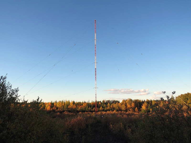 |
| YPM - 274 courtesy: VE3GOP |
This coming weekend will see another monthly CLE challenge. The hunting grounds will be the 50 kHz swath from 270 - 319.9 kHz, with much of this is being shared by DGPS signals here in North America.
The last time this range was covered was in CLE 212, back in October 2016. Conditions were particularly disturbed back then, as described in my CLE 216 Results blog at the time. Propagation should be much better this time, I hope!
For those unfamiliar with this monthly activity, a 'CLE' is a 'Co-ordinated Listening Event', as NDB DXers around the world focus their listening time on one small slice of the NDB spectrum.
A nice challenge in this one is to hear the Pikangikum (ON) NDB, 'YPM', on 274 kHz. Although just a 25-watter, thanks to its large vertical, YPM is well-heard throughout North America. Will you log it as well?
Look for 'YPM's upper-sideband CW identifier, repeated every 10.5 seconds, on 274.352 kHz with your receiver in the CW mode.
If you are interested in building a system for the new (U.S.) 630m band, the CLE will give you the chance to test out your MF receiving capabilities and compare against what others in your area might be hearing. You will soon know how well your system is hearing.
When tuning for NDBs, put your receiver in the CW mode and listen for the NDB's CW identifier, repeated every few seconds. Listen for U.S. NDB identifiers approximately 1 kHz higher or lower than the published transmitted frequency since these beacons are modulated with a 1020 Hz tone approximately.
For example, 'AA' in Fargo transmits on 365 kHz and its upper sideband CW identifier is tuned at 366.025 kHz while its lower sideband CW ident can be tuned at 363.946 kHz. Its USB tone is actually 1025 Hz while its LSB tone is 1054 Hz.
Often, one sideband will be much stronger than the other so if you don't hear the first one, try listening on the other sideband.
Canadian NDBs normally have an USB tone only, usually very close to 400 Hz. They also have a long dash (keydown) following the CW identifier.
All NDBs heard in North America will be listed in the RNA database (updated daily) while those heard in Europe may be found in the REU database. Beacons heard outside of these regions will be found in the RWW database.
Here are the final details from CLE organizer Brian Keyte, G3SIA:
Our 229th co-ordinated listening event is this weekend, covering a 50 kHz
frequency range - about three times wider than usual.
Days: Friday 23 February - Monday 26 February
Times: Start and end at midday, your LOCAL time
Range: 270.0 - 319.9 kHz
Targets: NDBs (NOT the DGPS beacons)
We can expect very good propagation, but in part of the frequency range
it might be quite a challenge to tease out the NDB signals from among
the DGPS ones.
Any first-time CLE logs will be very welcome, as always.
Please log the normal NDBs you can identify that are listed in the range
(it includes 270 kHz but not 320 kHz).
Please send your CLE log to NDB List, if possible as a plain text email
and not in an attachment, with 'CLE229 FINAL' at the start of its title.
Show on EVERY line of your log:
# The Date (e.g. '2018-02-23' or just '23', etc.)
# UTC (the day changes at 00:00 UTC).
# kHz - the beacon's nominal published frequency if you know it.
# The Call Ident.
Those main items can be in any order within themselves, but BEFORE any
other optional details (Location, Distance, etc.) later in the same line.
As always, give details in your log of your own location and the receiver,
aerial(s), etc. that you were using.
If you send any interim logs, be sure to send a FINAL (complete) one.
You can find anything else to help you, including seeklists for your part
of the World, from the CLE page, http://www.ndblist.info/cle.htm
Joachim or I will send the usual 'Any More Logs?' email at about 18:00 UTC
on Tuesday so that you can check that your CLE log has been found OK.
Do make sure that your log has arrived at the very latest by 09:00 UTC
next Wednesday, 28th February.
We are hoping to make all the combined results on that day.
Enjoy your listening
Brian
----------------------------------------------------------
From: Brian Keyte G3SIA ndbcle'at'gmail.com
Location: Surrey, SE England (CLE coordinator)
----------------------------------------------------------
(Reminder: You could use any one remote receiver for your loggings,
stating its location and owner - with their permission if required.
A remote listener may NOT also use another receiver, whether local
or remote, to obtain further loggings for the same CLE).
Posted by: "Brian Keyte" <9sm@waitrose.com>
These listening events serve several purposes. They:
- determine, worldwide, which beacons are actually in service and on-the-air so the online database can be kept up-to-date
- determine, worldwide, which beacons are out-of-service or have gone silent since the last CLE covering this range
- will indicate the state of propagation conditions at the various participant locations
- will give you an indication of how well your LF/MF receiving system is working
- give participants a fun yet challenging activity to keep their listening skills honed
Final details can be found at the NDB List website, and worldwide results, for every participant, will be posted there a few days after the event. If you are a member of the ndblist Group, results will also be e-mailed and posted there.
The very active Yahoo ndblist Group is a great place to learn more about the 'Art of NDB DXing' or to meet other listeners in your region. There is a lot of good information available there and new members are always very welcome. As well, you can follow the results of other CLE participants from night to night as propagation is always an active topic of discussion.
You need not be an ndblist member to participate in the CLEs and all reports, no matter how small, are of much value to the organizers.
'First-time' logs are always VERY welcome!
Reports may be sent to the ndblist or e-mailed to either myself or CLE co-ordinator, Brian Keyte (G3SIA), whose address appears above.
Please ... give the CLE a try ... then let us know what NDB's can be heard from your location! Your report can then be added to the worldwide database to help keep it up-to-date.
Have fun and good hunting!
Steve McDonald, VE7SL, is a regular contributor to AmateurRadio.com and writes from British Columbia, Canada. Contact him at ve7sl@shaw.ca.
LHS Episode #210: Tripping Over Neurodiversity
 In this slightly manic episode of Linux in the Ham Shack, the hosts discuss a variety of topics including building SDR antennas out of garbage, the pseudoscience of neurodiversity, training programs for teachers in technology, millenials amateur radio, open source hardware, how to behave in an increasingly PC world, fldigi on an RPi and much, much more. Thank you for tuning in, as always.
73 de The LHS Crew
Russ Woodman, K5TUX, co-hosts the Linux in the Ham Shack podcast which is available for download in both MP3 and OGG audio format. Contact him at russ@bluecows.com.
We’re Giving Away a HackRF One SDR and 49 More Prizes from NooElec!
 NooElec and AmateurRadio.com
have teamed up to give away a
HackRF One SDR Transceiver Package
and…
Over 49 other great prizes!
That’s 50 prizes — over US $2,000 worth!
This giveaway is open to
licensed ham radio operators worldwide.
…and NooElec will even pay the shipping!
The deadline to enter is Sunday 25 February 2018 at 20:00 UTC.
Matt Thomas, W1MST, is the managing editor of AmateurRadio.com. Contact him at editor@amateurradio.com.
Weekly Propagation Summary – 2018 Feb 19 16:10 UTC
Here is this week’s space weather and geophysical report, issued 2018 Feb 19 0416 UTC.
Highlights of Solar and Geomagnetic Activity 12 – 18 February 2018
Solar activity was at very low levels on 13-18 Feb and low levels on 12 Feb. The strongest flare of the period was a C1 from Region 2699 (S07, L=165, class/area Dai/240 on 10 Feb) at 12/0135 UTC. The event produced an associated asymmetric halo signature first observed in SOHO/LASCO C2 imagery at 12/0125 UTC. Analysis and modeling of the event suggested arrival of the CME at Earth on 15 Feb.
No proton events were observed at geosynchronous orbit.
The greater than 2 MeV electron flux at geosynchronous orbit was at background levels 12-16 Feb. An increase to moderate levels on 17 Feb and to high levels on 18 Feb was observed in response influence from a negative polarity CH HSS.
Geomagnetic field activity ranged from quiet to active levels. Quiet conditions were observed on 12-14 Feb. On 15 Feb, arrival of the 12 Feb CME produced only one isolated period of active during the day. Total magnetic field strength increased to a peak of 15 nT around 16/0530 UTC while Bz remained mostly positive. Solar wind speeds were relatively slow, between 300-400 km/s through the event. Active levels were reached again on 17 and 18 Feb in response to influence from a negative polarity CH HSS. Solar wind speeds continued to increase over the two days to a peak of about 600 km/s late on 18 Feb.
Forecast of Solar and Geomagnetic Activity 19 February – 17 March 2018
Solar activity is expected to be very low through the outlook period.
No proton events are expected at geosynchronous orbit.
The greater than 2 MeV electron flux at geosynchronous orbit is expected to range from normal to high levels. High levels from CH HSS influence are expected from 19-25 Feb. A transition back to normal levels is expected from 26 Feb to 17 Mar.
Geomagnetic field activity is expected to range quiet to G1 (Minor) geomagnetic storm conditions. Influence from a negative polarity CH HSS is expected to produce isolated periods of G1 (Minor) storming on 19 Feb. A decrease to quiet to active levels by 20 Feb and quiet to unsettled levels over 21-23 Feb is expected as influence from the CH HSS slowly wanes. Quiet to unsettled levels are again expected on 04 Mar and 15 March, with quiet to active levels expected on 14 Mar and 16-17 Mar, as multiple, recurrent CH HSSs are anticipated to become geoeffective. The remainder of the outlook period is expected to observe quiet conditions.
Don’t forget to visit our live space weather and radio propagation web site, at: http://SunSpotWatch.com/
Live Aurora mapping is at http://aurora.sunspotwatch.com/
If you are on Twitter, please follow these two users: 1. https://Twitter.com/NW7US 2. https://Twitter.com/hfradiospacewx
Check out the stunning view of our Sun in action, as seen during the last five years with the Solar Dynamics Observatory (SDO): https://www.youtube.com/watch?v=zXN-MdoGM9g
= = = = =
BOOK SALE: Space Weather and Sun Science – get these from Amazon, and help us stay online!
NOTICE: When you buy this (or any item after starting with this link), you are helping us keep our SunSpotWatch.com and other resources “on the air” (up and running!). In other words, you are helping the entire community. So, check out this book:
Here is the link to Amazon: http://g.nw7us.us/fbssw-aSWSC
We’re on Facebook: http://NW7US.us/swhfr
Visit, subscribe: NW7US Radio Communications and Propagation YouTube Channel
Update on acquiring my UK call

Mike Weir, VE9KK, is a regular contributor to AmateurRadio.com and writes from New Brunswick, Canada. Contact him at ve9kk@hotmail.com.
ICQ Podcast Episode 260 – Xiegu X108G Review
In this episode, Martin M1MRB is joined by Chris Howard M0TCH, Dan Romanchik KB6NU and Ed Durrant DD5LP to discuss the latest Amateur / Ham Radio news. Colin M6BOY rounds up the news in brief, and this episode’s feature is Xiegu X108G Review by Ed Durrant DD5LP.
We would like to thank our monthly and annual subscription donors for keeping the podcast advert free. To donate, please visit - http://www.icqpodcast.com/donate
- Solar Minimum Sunspot
- ARRL Again Calls for Action on Symbol Rate Limits
- Theft of MB7TV SSTV Repeater
- 160m Band Wireless Power Transfer
- Sony to Cease Shortwave Radios Production
- Yaesu FT818
- Kempton Rally
- UK QSL Bureau Volunteers Wanted
- The CWops Award for Advancing the Art of CW
Colin Butler, M6BOY, is the host of the ICQ Podcast, a weekly radio show about Amateur Radio. Contact him at info@icqpodcast.com.
 Ham Radio Deluxe |
 W5SWL Electronics |
 Ham Radio Prep |
 KB3IFH QSL Cards  Hip Ham Shirts  HamRadioAuctions HamRadioAuctions Reliance Antennas Reliance Antennas Enigma Shop Enigma Shop |  morseDX  Ni4L Antennas  R&L Electronics R&L Electronics antennas.us antennas.us Ears to Our World Ears to Our World |
- Matt W1MST, Managing Editor
