 Twenty Six SOTA Summits
 I’ve written before about how operating goals can be a good motivator for getting on the air and making ham radio contacts. It is fun to have a goal to work towards and keep checking items off on the list. A few years ago, I decided to apply this approach to Summits On The Air (SOTA). SOTA is ripe for this kind of thing, given its extensive database and tracking of QSOs.
Our family has a cabin in the mountains that we use to hike, jeep, ski, snowshore, explore, escape … So I decided to make a list of the SOTA summits in the general vicinity of the cabin. I did not use a precise criteria, just listing the summits that seemed close by. I used the Lists Of John web site as a tracking tool. That site is used by hikers/climbers to track their ascents, often working on their own list of summits based on whatever criteria that interests them.
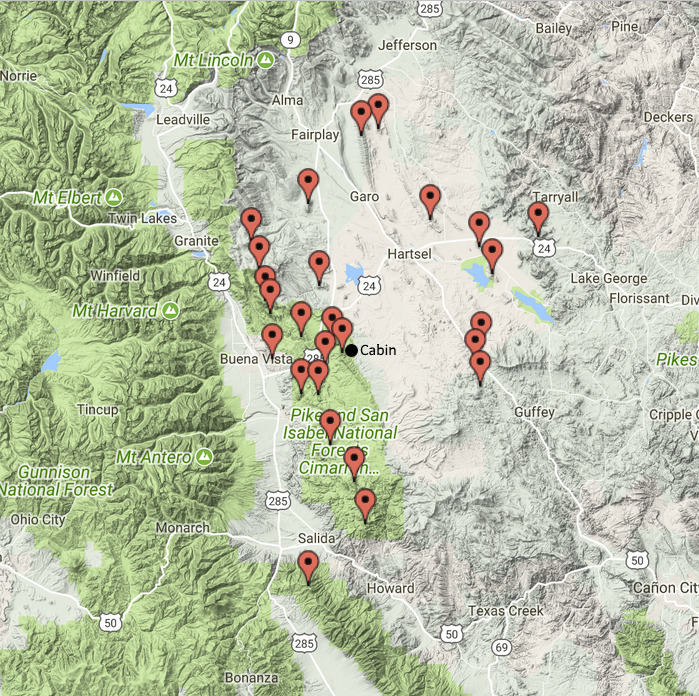 This list turned out to have 26 summits on it and I completed the last one a few months back, which was an unnamed peak (W0C/SP-055). Fifteen of these were the first activations of those summits. Some of these have still not been activated by anyone else (except for Joyce K0JJW, who usually hikes with me).
Now that I have completed that list, I obviously need to create a new one. With all of the SOTA summits available in Colorado, I won’t run out of options any time soon.
73, Bob K0NR
The post Twenty Six SOTA Summits appeared first on The KØNR Radio Site.
Bob Witte, KØNR, is a regular contributor to AmateurRadio.com and writes from Colorado, USA. Contact him at [email protected].
 More Autumn Antenna Adventures….
…with Arduino.
Last time I showed you how easy it is to hook up a relay to an Arduino MCU. Without some human control, however, it is a pretty useless setup. It needs switches and the switches most used in the Arduino world are momentary push buttons. They are versatile as just by altering some code you can change a momentary switch into a toggle switch or a rotary switch. Nifty!  Hooking them up is not quite straightforward, though, because they need either a pull-up resistor or a pull-down resistor. The voltages on Arduinos I/O (input/output) pins alter between two states: 0 and +5 Volt. When an I/O pin is connected to either ground (pulled down, LOW) or +5V (pulled up, HIGH) by shorting a switch, this state is easily read by the Arduino. But when the switch is not shorted the I/O pin “floats” and its state is not certain due to electrical noise; it might be anywhere between 0 and +5V. It’s difficult to tell what the Arduino will read then: either HIGH or LOW, but this is anybody’s guess. To prevent this from happening both ground and +5V are connected to the switch to make sure the I/O pin will see two clear states. To prevent damage due to high currents a 10k resistor is added.
With that out of the way and everything hooked up the fun stuff can begin. 
Just like last time we first define what I/O pins we use. Apart from the relayPin we now also have a buttonPin, namely A0. In the setup we now declare that buttonPin is used for INPUT, as we already defined that the relayPin is used as an OUTPUT pin.
The part which the Arduino loops through (over and over) looks a bit more complex now. It features an “if” statement:
if (digitalRead(buttonPin) == HIGH) {
 digitalWrite(relayPin, HIGH);
 }
This is not so difficult as it looks. In plain English it reads: “if you read out the buttonPin and it is equal to HIGH, execute the commands that are sandwiched in between { and }“. And the single command is the same as last time: write to the relayPin and make it active, or HIGH.
But what in other cases? That is the next part, which begins with “else“.
else {
 digitalWrite(relayPin, LOW);
 }
In all other cases make the relayPin LOW or inactive.
The result of all this you can see in the following short video.
Better, but still not useful enough. Once we release the button our relay also deactivates. A toggle switch is what is needed in this case, so let’s change the code and make it into one.
And this is where I find joy in working with Arduinos. With just three lines of code I can change the behaviour of a push button. There are loads of examples on the web that use lots more code to achieve the same result, but by being clever it can be done far more efficiently. Discovering this gives me the same kick as working a new DXCC entity, or building a circuit which works the first time. Although it almost wrecks my brain sometimes, the reward makes it all worth it.
Let’s take a quick look at the code. If the Arduino finds that the switch is activated, the buttonPin read HIGH. Only then execute a single command…
digitalWrite(relayPin, !digitalRead(relayPin));
“Write to the relayPin and make it the opposite (!) of the state it is in when you read out the relayPin“. So when the relayPin is HIGH, make it LOW and vice versa. The exclamation mark is short for “not” or in this case “the opposite“. Even though we defined that the relayPin is used for OUTPUT, that doesn’t mean you can’t read the status of it. Genius, isn’t it?
To finish it off we add a little delay to prevent button bounce, because this will happen when you use momentary push buttons. (For Arduino purists: I know there are much better ways to combat button bounce – even hardware solutions – but for this article I’d like to keep things as simple as possible: KISS all over).
At the end of the day we now have one problem solved and our switchable loop antenna is one step closer to completion. The next problem: how to tune the loop?
Hans "Fong" van den Boogert, BX2ABT, is a regular contributor to AmateurRadio.com and writes from Taiwan. Contact him at [email protected].
 LF Tests From WH2NXD / NI7J
For those of you with an interest in amateur LF work, you may be interested in the upcoming WSPR test transmissions from Ron, WH2XND / NI7J, located in Phoenix, Arizona.
One of Ron's several experimental licences allows him to run as much as 10W ERP from 68-76 KHz. To generate this amount of ERP at 75 KHz requires a lot of power and I suspect that he will still be well under his licence limitations ... amateur-sized antennas are just not very efficient on these low fequencies.
Previous experiments a few years ago, at lower ERP, produced impressive results, as shown by one of the WSPRnet maps for an overnight session on 75.075 KHz.
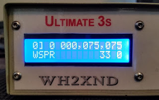
Ron used one of the Hans Summers U3S transmitters to generate his LF WSPR signal, amplifying it with a 400W Hafler audio amplifier. This winter's tests will be at 800W, with a W1VD FET amplifier designed for VLF.
Ron's experimental licence also covers 470 - 495 KHz at a whopping 100W ERP and 130 - 140 KHz at 50W ERP ... some serious power.
You may also find Ron's interesting and well-illustrated website description of some experimental antenna work that he has been doing on MF, LF and what it takes to resonate a typical Marconi 'T' on these bands.
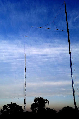 |
| MF- LF 'T' Antenna At WH2XND |
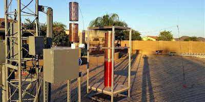 |
| 75 KHz Loading Coils! |
Ron has tentatively chosen late November or early December for his 'almost' VLF tests and when the date and frequency are finalized, I will post the information here on the blog.
Steve McDonald, VE7SL, is a regular contributor to AmateurRadio.com and writes from British Columbia, Canada. Contact him at [email protected].
 TyMD380tools for Tytera MD-380
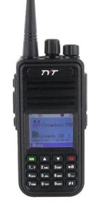 The Tytera MD-380 is an low cost radio for analog FM and DMR on the 70cm band (see video here). One of the limitations with the radio is that it only holds 1000 contacts…which seems like a lot of contacts but it fills up quickly. With DMR, each radio or user has a unique 7-digit radio ID number. For ham radio use, the DMR-MARC organization maintains a database that maps radio ID number to user name and callsign. If a user is in your contact list, the user’s name and callsign pops up in your radio’s display. Otherwise, you just see the radio ID which is not very helpful. There are over 63,000 users in the database with more being added on a daily basis.
There are a number of firmware updates to the MD380 and I have not checked them all out. I heard some guys talking about the TyMD380Tools on one of the DMR talkgroups, so I decided to give it a try. This software was developed by KG5RKI (go here) and is easily installed from Windows without a lot of messing around. This firmware upgrade loads the entire DMR-MARC database into the radio.
Now that I have the worldwide database of DMR users loaded onto the radio, its like having caller ID on my HT (see photo below). Actually, its better than that, it pulls up the other ham’s full name, callsign and location information.
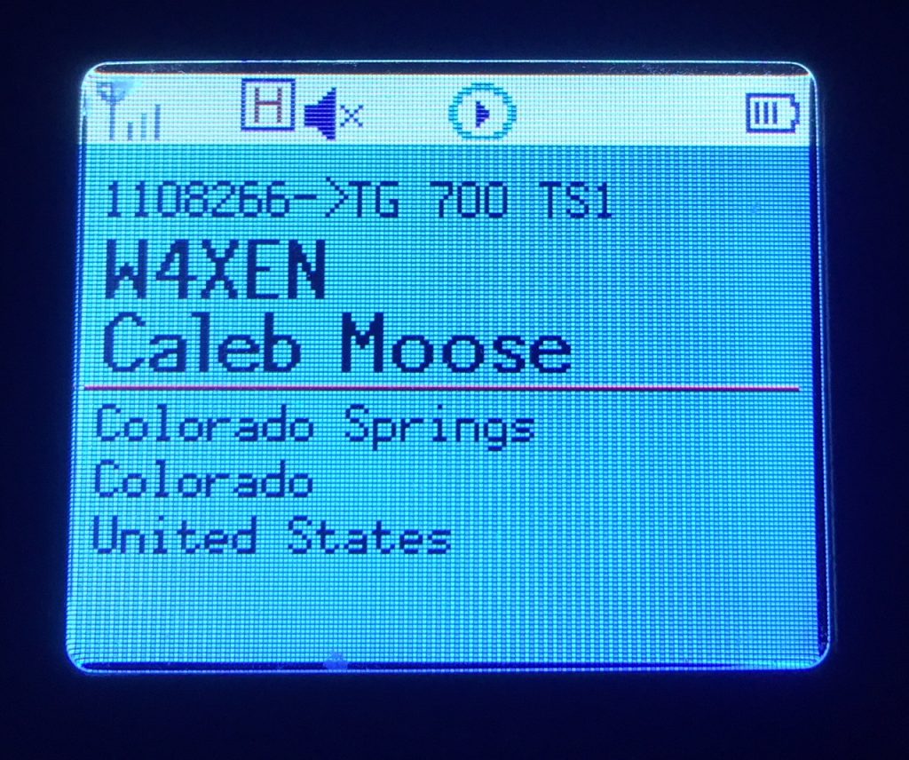 This may not seem like a big deal but I’ve found it to be surprisingly useful. I am often scanning a few channels or talkgroups with my radio and just listening casually. I may not be tracking who’s talking but I can just look at the radio to see who’s on the air. It’s one of those convenience features that makes me think “why don’t all of my radios do this?”
The TyMD380Tools implements a bunch of other features but increasing the number of contacts has been the most important one for me. This is a great example of radio amateurs adapting (“hacking”) commercial gear with improvements for ham radio use. KK4VCZ, DL4YHF and others contributed to this code. Check out the software…seems to work great.
73, Bob K0NR
The post TyMD380tools for Tytera MD-380 appeared first on The KØNR Radio Site.
Bob Witte, KØNR, is a regular contributor to AmateurRadio.com and writes from Colorado, USA. Contact him at [email protected].
 Going about it the hard way…..WHY??
Last evening I finally had some time to get on the PC and check out what fellow ham radio bloggers were up too. For the past month I have been working every day and only having time to “fast read” a post and drop a short comment. While surfing the blog sphere last evening I came across KG3V’s blog, the subject of the blog caught my attention “Updating FTDX-3000 Firmware. Below is a link to what I only could call an “adventure”.
https://kg3v.com/2017/10/14/updating-ftdx-3000-firmware/
In the post Tom does a great job explaining how he went about the firmware upgrade and some issues he ran into. Tom also goes over the enhancements this firmware will forward to his FTDX-3000. It’s fantastic how far we have come in radio, in the past if you wanted the upgrades it meant selling what you had and purchasing the new and improved version. Today’s modern rigs can chat either over the internet or with pre-downloaded thumb drives and magic is worked within the rig to either over come an issue, enhance what is already there or add something new! Having said that I just can’t understand what the issue is with the process of the upgrade. It’s just not ham radio with our Nikon cameras to upgrade the firmware it’s…hold this while pushing that….make sure you don’t do this while doing that….and on and on and on. Resources are used writing the rigs new firmware upgrade, time and money is put into it and it’s to make the product better for the end user. If this is the case why the %&^* not make the process for the end user easy peasy!!
Having said the above and let me preface this with “I am not going to say what I am about to say just because I am a fan of Elecraft but if the shoe fits……” To upgrade my K3 or KX3 Elecraft has provided via their website a program that sits on your desktop, one of it’s functions is for firmware upgrades. The process is as follows:
1. Double click on desktop icon.
2. Click on Firmware tab.
3. Click on “Check versions now”
4. Below you will then see the firmware that is installed in your rig and new firmware that is available for your rig. You then click on “Send all new firmware to K3 or KX3.
Your rig will start to click, there will be “stuff” flashing on the rigs screen, sometimes even clicking noises from the rig and then your rig’s screen returns to normal and your done. I have owned Kenwood, Icom and Yeasu rigs and never has it been this easy and my question is WHY NOT!!! Now having said the above it is true I have not owned one of the above rigs for some time now so do comment if the process has changed…but is sure does not seem it has for the FTDX-3000 model rig!
OK I’m off my soapbox now….:))
Mike Weir, VE9KK, is a regular contributor to AmateurRadio.com and writes from New Brunswick, Canada. Contact him at [email protected].
 ICQ Podcast Episode 250 – Building Mobile Station (Flossie), RSGB Online Exams and Yaesu DR-2X
In this episode, Colin M6BOY is joined by Leslie (G0CIB), Edmund (M0MNG), Bill (N3JIX) and Matthew (M0NJX) to discuss the latest Amateur / Ham Radio news and this episode’s feature is a triple from UK Hamfest - RSGB Online Examination, Building a Mobile Station (Flossie) and Yaesu tell us more about the DR-2X
We would like to thank Robert Mens (PD0RMX), Grant Porter (KG4SDR), Nick Major (G0HFL), two anonymous donors and our monthly and annual subscription donors for keeping the podcast advert free. To donate, please visit - http://www.icqpodcast.com/donate
- Traditional Ham Radio No Longer So Attractive
- RF pollution from LED bulbs in Germany
- FCC Tells Apple Turn on iPhone's FM Radio Chip
- School Students Ham Radio Link to Puerto Rico
- Newburgh Teen Supports with Amateur Radio
- Symbol Rate Restrictions - FCC Grants Temporary Waiver
Colin Butler, M6BOY, is the host of the ICQ Podcast, a weekly radio show about Amateur Radio. Contact him at [email protected].
 AmateurLogic 109: ALTV’s 12th Anniversary
AmateurLogic.TV Episode 109 is now available for download.
Celebrate ALTV’s 12th Anniversary with us. Emile prepares for a spooky Halloween with Sonic Pi. Unveiling the new RigPi. Mike, VE3MIC updates us on recent projects. Icom/MFJ/Heil Sound/AmateurLogic IC-7300 base station giveaway.
1:40:13
George Thomas, W5JDX, is co-host of AmateurLogic.TV, an original amateur radio video program hosted by George Thomas (W5JDX), Tommy Martin (N5ZNO), Peter Berrett (VK3PB), and Emile Diodene (KE5QKR). Contact him at [email protected].

