 The May ‘Bug Roundup’
 |
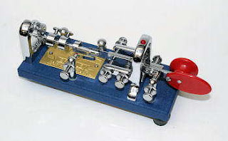
| Vibroplex "Blue Racer" |
Ever since earning my ticket as a teenager back in '63, almost all of my on-air activity has been focused on CW ... I've always loved it.
For my first year on-the-air, I used a nice brass hand key purchased locally for just a few dollars but once I had mastered that and I was just unable to send any faster with it, I purchased a Vibroplex 'Original', for, if memory serves me correct, around $40. I used it exclusively until building a homebrew memory keyer in the mid-70's and the Vibroplex saw little service for several years.
 |
| The Vibroplex 'Original' |
So much has changed now with the almost exclusive use of electronic keyers and everyone pretty much sounds the same, which is rather a pity I think.
Once my interest in building vintage-style vacuum-tube transmitters evolved, my interest in bugs was reactivated and over the years I have purchased a few more.
I'll do anything I can to promote and encourage the use of CW and especially hand-generated CW. That's why I was excited to read a recent e-mail from W6SFM, posted to several lists that I read, announcing the Bug Roundup!
Reserve the day! Saturday May 20th - Sunday May 21st, 2017
7:00 AM to 7:00 AM Pacific Time (LOCAL)
1400 UTC through 1400 UTC
For more information, to register your station and key for participation, and to help assist in spotting, potentially increasing QSOs, an On-line chat window link can be found near the bottom of Bug Roundup home page located at http://www.w6sfm.com/Bug_Roundup.html We hope to hear you all on the air!
Steve McDonald, VE7SL, is a regular contributor to AmateurRadio.com and writes from British Columbia, Canada. Contact him at [email protected].
 The May ‘Bug Roundup’
 |
| Vibroplex "Blue Racer" |
Ever since earning my ticket as a teenager back in '63, almost all of my on-air activity has been focused on CW ... I've always loved it.
For my first year on-the-air, I used a nice brass hand key purchased locally for just a few dollars but once I had mastered that and I was just unable to send any faster with it, I purchased a Vibroplex 'Original', for, if memory serves me correct, around $40. I used it exclusively until building a homebrew memory keyer in the mid-70's and the Vibroplex saw little service for several years.
 |
| The Vibroplex 'Original' |
So much has changed now with the almost exclusive use of electronic keyers and everyone pretty much sounds the same, which is rather a pity I think.
Once my interest in building vintage-style vacuum-tube transmitters evolved, my interest in bugs was reactivated and over the years I have purchased a few more.
I'll do anything I can to promote and encourage the use of CW and especially hand-generated CW. That's why I was excited to read a recent e-mail from W6SFM, posted to several lists that I read, announcing the Bug Roundup!
Reserve the day! Saturday May 20th - Sunday May 21st, 2017
7:00 AM to 7:00 AM Pacific Time (LOCAL)
1400 UTC through 1400 UTC
For more information, to register your station and key for participation, and to help assist in spotting, potentially increasing QSOs, an On-line chat window link can be found near the bottom of Bug Roundup home page located at http://www.w6sfm.com/Bug_Roundup.html We hope to hear you all on the air!
Steve McDonald, VE7SL, is a regular contributor to AmateurRadio.com and writes from British Columbia, Canada. Contact him at [email protected].
 ICQ Podcast Episode 236 – Dummy Loads
In this episode, Martin M1MRB / W9ICQ is joined by Leslie Butterfield G0CIB, Edmund Spicer M0MNG and Matthew Nassau M0NJX to discuss the latest Amateur / Ham Radio news. Colin M6BOY rounds up the news in brief, and this episode’s feature is Dummy Loads
- 50 MHz Band Experimentation
- 5 GHz - RSGB Respond to Ofcom
- Israeli Students Build CubeSat
- UKQRM Launches New Campaign for UK Election
- Amateur Radio Duo Honoured
- Hungarian 5MHz Beacon HG7BHB Closed Down
- D-STAR Gateway Version 3 ('G3') Software Available to UK Repeater Keepers
- FCC Proposes $400,000 Jammer Fine
Colin Butler, M6BOY, is the host of the ICQ Podcast, a weekly radio show about Amateur Radio. Contact him at [email protected].
 Amateur Radio …. sort of
I had a class this morning that meets one Saturday a month. It started last September and ends next month, and it runs from 9:00 AM to 1:00 PM. You can see that that's a good chunk of the day. So it was SOTABEAMS WSPRLite to the rescue! It's kind of like a Ronco counter top oven - "set it and forget it". So I hooked up my WSPRLite to my W3EDP, set it up for 200 milliWatts on 20 Meters and let it go to town!
I figured that I'd let it run, see how the W3EDP gets out and still do the things I had to do today.
This WSPRLite is so cool! It's a software defined WSPR beacon in a package about half the size of an Altoids tin. It's powered by the USB port of your computer. You pick the band and power output and hook it up to your antenna. You wait until 2 seconds past any even minute and you press the little black button on the right to kick things off. The beacon transmits for 110 seconds and then waits for the next opportunity when the frequency is clear. I set it so that it would randomly transmit about 20% of the time; and you can let it run for up to three days if you want.
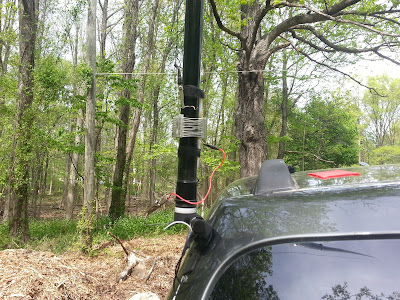
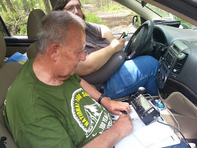
In the meantime, yesterday, while checking my e-mail, I saw that Joe Everhart N2CX co-founder of the NJQRP Club was going to be activating Edison State Park for Parks on the Air. It's designator is KFF-1615 and it's all of about 15 minutes from my house. So I e-mailed Joe back with my cell phone number and told him to text me when he got there; and I would come out and meet him.
After class I came home and broke out the lawnmower and got the front yard done. As I was walking to the backyard, I felt my pocket buzz. I whipped out my phone and read a text that Joe was on site and setting up. I dropped the lawnmower like a hot potato and high tailed it to the park. After all, what QRPer in his right mind would miss the opportunity to talk with a QRP Legend, right? When I got there, I saw Joe had finished setting up and was operating from his car.
It was getting out all right! Into the midwest USA and into Europe on 200 milliWatts! The W3EDP seems to be doing OK!
It turned out to be a good day, after all. I got to attend my class, got my chores done and got to hob-nob with a QRP giant - while giving my wire antenna a check out at the same time!
And here I thought the day would be a bust, Amateur Radio-wise!
72 de Larry W2LJ
QRP - When you care to send the very least!
Larry Makoski, W2LJ, is a regular contributor to AmateurRadio.com and writes from New Jersey, USA. Contact him at [email protected].
 Amateur Radio Weekly – Issue 156
FCC changes will affect GMRS, FRS, CB, other Part 95 devices
DXing on Citizens Band will become legal.
ARRL
Man fined $500 for writing ‘I Am An Engineer’ in email to government
An electronics engineer says he found a flaw in traffic lights. The Oregon engineering board fined him for it.
Motherboard
Heads up: An invasion is coming
Yep, thousands of Hams are expected to converge on our county fairgrounds for a three day event known as the ‘Hamvention.”
Fairborn Daily Herald
USB CW Key
Enable a key to be used as mouse input via USB.
whaley.org.uk
Requiem For Radio project
Artist Amanda Dawn Christie has brought back to life the sounds of the 13 CBC Radio-Canada International shortwave towers that once stood in Sackville, N.B.
CBC
How to broadcast color PAL and NTSC television with an SDR
This project describes my approach and success in transmitting an analog color TV image via a HackRF One.
hackaday.io
VHF SOTA Expedition in the Snowdonia National Park
I stayed a total of 8 days and activated 11 summits.
Adventures in Ham Radio
The Cricket: The Four State QRP Group’s latest transceiver kit
The Cricket is a low cost entry level minimalist CW transceiver for the 80 meter band.
The SWL Post
Contesting in Hawaii – H2O versus your antennas
The elements always win…meaning water. Well, the Sun plays a role as does wind. Nothing like the repeated pounding that trade winds do to break or loosen something.
ARRL and Ham Radio in Hawaii
Video
MFJ-269C testing coax cable faults and length
The MFJ-269C is so much more than an SWR analyzer.
Ham Radio Concepts
Ham Radio Headset Shootout: Budget vs. High-End
Discussing two very popular headsets in the Amateur Radio community in this video.
YouTube
Amateur Radio Weekly is curated by Cale Mooth K4HCK. Sign up free to receive ham radio's most relevant news, projects, technology and events by e-mail each week at http://www.hamweekly.com.


