 Crypto virus how safe is Digital broadcasting?
More and more radio stations have recently been pulling the plug on Shortwave, and AM broadcasting, in favour of digital. There has been a big push in the UK to get the public over to DAB (Digital Audio Broadcasting) or streaming radio via their mobile phones and computers. But, has the case now been made to "keep" a national simulcast AM radio system, like the BBC's Radio 4 Long Wave in the UK, along with global Shortwave radio transmissions for state broadcasting in emergency?
Steve, G1KQH, is a regular contributor to AmateurRadio.com and writes from England. Contact him at g1kqh@arrl.net.
 ETH068 – Are You Weather Aware?
While having access to your local RADAR wherever you are is great, you shouldn’t depend on it totally. You should be able to look at the sky, feel the wind, and see other clues to have an idea of what could be coming your way.
This brings up the question:
Are You Weather Aware?
In episode 68, we talk about this question and some things that you need to learn and do to help yourself be weather aware. Things like knowing what to look for in the clouds, why the wind suddenly changed directions, what to have in your emergency kit and having a plan with your family in case you need to vacate your home or seek shelter inside.
We dive into several weather events like tornadoes, flash floods, hail and even the event with the highest average of fatalities, which might surprise you.
We talk about W5KUB with the Amateur Radio Roundtable as he does his Hamvention coverage including the drive to and from. We also talk about some other hamfests that are coming up over the next two weeks.
If contesting is you thing, we talk about all the upcoming contests/on-the-air events for the next two weeks as well.
Check out the show notes and listen to the episode at:
http://www.everythinghamradio.com/podcast/68
Curtis Mohr, K5CLM, is the author/owner of Everything Ham Radio Blog and Youtube channel. Contact him at k5clm@everythinghamradio.com.
 May’s ‘Red Ryder’ EME Ops

With the QSL's from last month's surprisingly good EME conditions just starting to arrive, May's moonbounce operation continued to produce good results.
Whether this is because of better than normal lunar path conditions or just a result of my neighbour's tree-pruning, remains to be seen.
The few days of operating in early May were, as usual, planned to take advantage of the Moon's closest approach as well as the Moon's most northerly declinations. The latter condition puts moonrises directly out in front of the house and looking across Georgia Strait's many miles of saltwater. The extra theoretical 'sea-gain' appears to be a reality under these conditions and allows my 9el Yagi to garner another 6db on both transmit and receive paths, making it perform more like a '4-Yagi' array.
Eight stations were worked this time around, with six of them being new 'initials', bringing my EME total from 95 to 101. Several of these stations were speaker-audible, at CW levels.
NTØV #96
IK7EZN #97
EA2AGZ #98
G4SWX
F6HVK #99
G4CDN #100
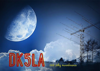
DK5LA #101
DK3BU
 | ||||
| IK7EZN's cross polarized 4 x 13 array |
 |
| EA2AGZ's 4 x 16 array |
 |
| DK5LA's cross polarized 8 x 16 array ...very loud! |
For now, any earlier thoughts of building a 4CX250 300 watt amplifier have been put on hold, while I continue to slowly work my way through what seems a never-ending list of workable stations.
Steve McDonald, VE7SL, is a regular contributor to AmateurRadio.com and writes from British Columbia, Canada. Contact him at ve7sl@shaw.ca.
 May’s ‘Red Ryder’ EME Ops

With the QSL's from last month's surprisingly good EME conditions just starting to arrive, May's moonbounce operation continued to produce good results.
Whether this is because of better than normal lunar path conditions or just a result of my neighbour's tree-pruning, remains to be seen.
The few days of operating in early May were, as usual, planned to take advantage of the Moon's closest approach as well as the Moon's most northerly declinations. The latter condition puts moonrises directly out in front of the house and looking across Georgia Strait's many miles of saltwater. The extra theoretical 'sea-gain' appears to be a reality under these conditions and allows my 9el Yagi to garner another 6db on both transmit and receive paths, making it perform more like a '4-Yagi' array.
Eight stations were worked this time around, with six of them being new 'initials', bringing my EME total from 95 to 101. Several of these stations were speaker-audible, at CW levels.
NTØV #96
IK7EZN #97
EA2AGZ #98
G4SWX
F6HVK #99
G4CDN #100
DK5LA #101
DK3BU
 | ||||
| IK7EZN's cross polarized 4 x 13 array |
 |
| EA2AGZ's 4 x 16 array |
 |
| DK5LA's cross polarized 8 x 16 array ...very loud! |
For now, any earlier thoughts of building a 4CX250 300 watt amplifier have been put on hold, while I continue to slowly work my way through what seems a never-ending list of workable stations.
Steve McDonald, VE7SL, is a regular contributor to AmateurRadio.com and writes from British Columbia, Canada. Contact him at ve7sl@shaw.ca.
 2017 Colorado 14er Event with SOTA
 Amateur Radio operators from around Colorado will be climbing many of Colorado’s 14,000-foot mountains and Summits On The Air (SOTA) peaks to set up amateur radio stations in an effort to communicate with other radio amateurs across the state and around the world. Well, last year we celebrated the 25th annual event so this year it must be the 26th. We are continuing the all weekend approach on August 5 and 6. However, many mountaintop activators will hit the trail early in the morning with the goal of being off the summits by noon due to lightning safety concerns.
We still have the very cool 25 Year Anniversary t-shirts (and other great stuff) available at http://www.cafepress.com/wg0at
The 14er event includes Summits On the Air (SOTA) peaks, which add over 1700 now 1805 potential summits! If you aren’t up to climbing a 14er, there are many other summits to choose from (with a wide range of difficulty). See the W0C SOTA web page at w0c-sota.org
Radio operators who plan to activate a summit should post their intent on the ham14er Yahoo Group. To subscribe to the “ham14er” email list, visit the Yahoo groups site at http://groups.yahoo.com/group/ham14er/ . Also, be sure to check out the event information at http://www.ham14er.org It is also a great idea to post an ALERT on the SOTAwatch.org website.
Frequencies used during the event
Activity can occur on any amateur band including HF, VHF and UHF. The 2m fm band plan uses a “primary frequency and move up” approach. The 2m fm primary frequency is 147.42 MHz. At the beginning of the event, operators should try calling on 147.42 MHz. As activity increases on that frequency, move on up the band using the 30 kHz steps. Don’t just hang out on 147.42 MHz…move up! The next standard simplex frequency up from 147.42 MHz is 147.45 MHz, followed by 147.48 and 147.51 MHz. We try to stay off 146.52 MHz, the National Simplex Calling Frequency to avoid overload, but if you need to make a call there, go for it…and be brief.
| Frequency (MHz) | Comments | Frequency (MHz) | Comments |
| 147.42 | Primary 2m FM Frequency, then up in 30 kHz steps | 7.032 | 40m CW Frequency |
| 147.45 | Alternate 2m FM frequency | 7.185 | 40m SSB Frequency |
| 147.48 | Alternate 2m FM frequency | 10.110 | 30m CW Frequency |
| 147.51 | Alternate 2m FM frequency | 14.060 | 20m CW Frequency |
| 446.000 | Primary 70 cm FM frequency | 14.345 | 20m SSB Frequency |
| 446.025 | Alternate 70 cm FM frequency | 18.092 | 17m CW Frequency |
| 144.200 | 2m SSB calling frequency | 18.158 | 17m SSB Frequency |
| 50.125 | 6m SSB calling frequency | 21.060 | 15m CW Frequency |
| 1294.50 | 23 cm FM calling frequency | 21.330 | 15m SSB Frequency |
| Other Bands/Modes | Standard calling frequencies and/or band plans apply. | 28.060 | 10m CW Frequency |
| 28.350 | 10m SSB Frequency |
Warning: Climbing mountains is inherently a dangerous activity.
Do not attempt this without proper training, equipment and preparation.
Sponsored by The Colorado 14er Event Task Force
The post 2017 Colorado 14er Event with SOTA appeared first on The KØNR Radio Site.
Bob Witte, KØNR, is a regular contributor to AmateurRadio.com and writes from Colorado, USA. Contact him at bob@k0nr.com.
 LHS Episode #188: A Sniffle of Coughers
 Thank you for tuning in to episode #188 of Linux in the Ham Shack. In this episode, the hosts discuss changes to FRS, GMRS and Citizen's Band regulations, morse code in Taiwan, an FCC frequency auction, new Linux, Android in a box, an ncurses interface for packet, Zesty Zapus, ham radio in OpenSUSE, chicken marsala and much more. Thank you for listening. Please donate to our Hamvention 2017 fund if you can. See you in Xenia!
73 de The LHS Guys
Russ Woodman, K5TUX, co-hosts the Linux in the Ham Shack podcast which is available for download in both MP3 and OGG audio format. Contact him at russ@bluecows.com.
 Back in the loop
My main project for at least the last 12 months has been building a solid magnetic loop antenna and its companion automatic loop controller. I’ve been roughly tracking its progress at my magnetic loop antenna project page on this blog.
As usual, life has got in the way, but I want to get back on track and complete the project. To start pumping some RF current through it again, over the weekend I spent a short time playing with the loop on WSPR on 40, 30 & 20m. The tests were too brief but they certainly confirm that the loop is capable of transmitting a signal in spite of the fact the loop is only half a metre above ground and surrounded by metal garden furniture, a steel framed awning and gutters.
I used the WSPR Beacon android app to control my transmitter. There was some discrepancy (tens of Hz) between the actual output frequencies on the app and those shown on WSPRnet. I also found that tuning the loop to each WSPR frequency using the iP30 antenna analyzer was easy and the KX2 gave lower SWR figures.
The brief test became an exercise in understanding theWSPRnet results taking into account propagation and loop orientation which was aligned north-south.

This map view combines all 20 spots of the 1W VK2RH transmissions from grid square QF56oc. The first test was logged at 2017-05-07 01:36 UTC. (I’ve trimmed repeated info from the chart below to improve its fit on the page.)
| Time | MHz | SNR | Drift | Reporter | RGrid | km | az |
| 05:24 | 14.097001 | -15 | 1 | VK4ALR | QG56fk | 1151 | 356 |
| 05:24 | 14.097016 | -26 | 0 | VK4TDI | QG62lm | 733 | 14 |
| 04:48 | 10.140109 | -22 | 0 | VK4TDI | QG62lm | 733 | 14 |
| 04:48 | 10.140094 | -23 | 0 | VK7TW | QE37pc | 1057 | 198 |
| 04:48 | 10.140091 | -17 | 0 | VK6XT | OF86td | 3086 | 261 |
| 04:40 | 10.140095 | -27 | 0 | VK7TW | QE37pc | 1057 | 198 |
| 04:40 | 10.140090 | -4 | 0 | VK3WE | QF32se | 547 | 216 |
| 04:40 | 10.140090 | -22 | 0 | ZL1RS | RF64vs | 2069 | 101 |
| 04:40 | 10.140092 | -15 | 0 | VK6XT | OF86td | 3086 | 261 |
| 04:40 | 10.140091 | -16 | 0 | ZL3GA | RE66ho | 2130 | 126 |
| 03:18 | 7.040121 | -24 | 0 | VK3BAL | QF22mc | 711 | 230 |
| 03:18 | 7.040134 | -7 | 0 | VK3AXF | QF33fn | 516 | 235 |
| 03:18 | 7.040135 | -18 | 0 | VK4MOB | QG62ol | 734 | 16 |
| 03:18 | 7.040130 | -18 | 0 | VK3DXE | QF21nv | 720 | 228 |
| 03:18 | 7.040128 | -12 | 0 | VK2TPM | QF56of | 14 | 0 |
| 03:18 | 7.040129 | -14 | 0 | VK7DIK | QE38cu | 918 | 207 |
| 01:36 | 7.040183 | -16 | -1 | VK3AXF | QF33fn | 516 | 235 |
| 01:36 | 7.040177 | -16 | -1 | VK2TPM | QF56of | 14 | 0 |
| 01:36 | 7.040184 | -24 | -1 | VK4MOB | QG62ol | 734 | 16 |
| 01:36 | 7.040179 | -21 | 0 | VK3DXE | QF21nv | 720 | 228 |
40 metres favoured north-south, while 30 metres was literally an all-rounder and 20 metres was too brief. These results probably say more about propagation than the loop, not to mention the heavy lifting done by all the reporter stations extracting my down to -26 or -27 dB signals from the noise! Impressive all round!
I wonder how many people are using the Sotabeams WSPRlite antenna tester device. Certainly looks tempting, especially for longer term antenna evaluation.
In any case, the main purpose of today’s exercise was to re-start the loop project. The To Do list includes
- building & installing the SWR bridge into the loop controller,
- deciding on the best way to couple the stepper motor shaft to the tuning capacitor shaft,
- and wiring it all together with appropriate coax and control cables.


