 Single Yagi Moonbounce
 |
| courtesy: JPL/NASA |
In early 2007, I decided to try 2m moonbounce using WSJT's JT65B digital mode. Over the years, moonbounce has gradually drifted away from CW to the much less demanding weak signal digital mode, allowing smaller stations to still explore the excitement of exchanging signals via reflection from the lunar surface. I am fortunate to have an excellent QTH for such an endeavour, being located beside the ocean with a saltwater horizon favoring moonrises, especially during the winter months of more northerly lunar declinations.
 |
| Moonrise from front yard |
I soon realized that the actual numbers appeared very close to predicted values and using an inexpensive 2m FM/SSB 'brick amplifier' (with built-in GasFet preamp) delivering approximately 140 watts, I was able to work 54 different stations over the next twelve months. All of the stations worked were doing the heavy lifting, with the majority running typical 4-yagi H-frame arrays using yagis from 6 to 17 elements each. I did work one station that was using two small yagis during a period of excellent conditions. Somewhat surprisingly, a large majority of the stations I worked were strong enough to be heard audibly from the transceiver's speaker.
I'm always amazed at the truly small amount of RF energy that is actually left, after the round trip to the moon ... yet information can still be exchanged. On 144MHz, the round trip losses are a minimum of 250db. Factoring-in my antenna's gain and ignoring the coaxial losses in 70' of RG213, there is a scant 1.56 x10^-9 W arriving at the moon ... that's .00000000156 W! Considering how much RF is absorbed in the lunar dirt and what's left over for the -125db home trip, it's a miracle that some signals are loud enough to be heard by ear at all. EME is really one of ham radio's most fascinating activities.
Reacquainting myself with the newer version of the JT65B software, and testing out the system, I was ready to go on the next evening's moonrise. Unfortunately the moon was rising just a little too far south to give me a really clear shot and I would be pointing into the next door neighbour's trees. Being unable to track the elevation, my operating time is limited to about two hours per session, over a period of several successive days (or nights).
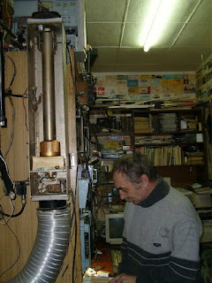
Almost coincidental with the night's moonrise, I heard the strong signals of RX1AS (Alex) in St. Petersburg, calling CQ. I called him and he came right back with my signal report. His station is shown below, along with his large homebuilt strip-line amplifier.
 |
| RX1AS |
The following evening, the moon was buried even deeper into the trees but initials #56 and #57 were worked ... YL2GD (Gunars), in northern Latvia and RX3A (Nikolay), in Moscow city.
 |
| YL2GD and his EME station |
 |
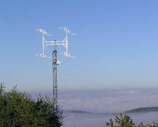
| RX3A's 2m EME array |
Nikolay was worked with the moon at 11 degrees above the horizon. I'm not sure just what my upper limit for lunar elevation might be with this small antenna but the highest elevation I have worked anyone was at 18 degrees.
The third night found less activity on the band as well as a more southerly moonrise, burying my target even further into the neighbour's trees. Few signal were heard but one contact was easily completed with I3MEK (Mario), near Venice ... initial #58.
 |
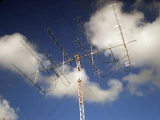
| I3MEK's 4-yagi 2m EME array |
 |
| I3MEK's 2m JT65b signal |
With so many larger (four or more yagis) stations around the world, a huge antenna is not needed to have success on 2m JT65B moonbounce ... nor is an over-the-ocean moonrise. I've also been able to work stations on moonset where I am pointing over hilly terrain and trees, nowhere near the ocean.
The WSJT (JT65B mode) software is freely available and very easy to implement, but spend some time reading the manual and playing with the software first, perhaps getting used to QSO procedures on 20m.
If you are running a small FM/SSB amplifier on 2m, such as the typical 'brick' I have been using, make sure to add a blower to keep the heatsink cool, as JT65 has a 100% duty cycle and these small amplifiers can get hot pretty fast. I use a small squirrel-cage blower from an old microwave oven to direct a blast of air onto the cooling fins.
Wondering where to point your antenna? One handy site that will provide the moon's position in the sky, for any time and any location, is the U.S. Naval Observatory's 'Sun or Moon Altitude/Azimuth Table'. As well, you can keep abreast of real-time activity or set up skeds, via NØUR's Ping Jockey JT65 EME page.
If you do decide to give this a shot, I'd be interested to hear how you do ... maybe your system is big enough already to let us work each other via the moon.
Steve McDonald, VE7SL, is a regular contributor to AmateurRadio.com and writes from British Columbia, Canada. Contact him at ve7sl@shaw.ca.
 Australian ham gives an insider’s tour of his antennas
 Rob Wagner, VK3BVW, gives an interesting and visually appealing tour of the antennas at his home in Mount Evelyn, Victoria, a small town in southeast Australia near the beautiful city of Melbourne.
His backyard features mostly wire antennas — 3 are double bazookas (or coaxial dipoles) — and includes a Par SWL End-Fedz antenna.
In addition to creating well-done ham radio videos, VK3BVW writes a blog called the Mount Evelyn DX Report.
Matt Thomas, W1MST, is the managing editor of AmateurRadio.com. Contact him at editor@amateurradio.com.
 Spring is nearly in the air, the new HF rig is ordered and on the way.
Obviously I have been a long time fan of Yaesu, I think they have made some very good radio gear over the years, still forefront leaders of the game with an excellent updated range to suit all pockets. How I came to choose this radio I will leave to another blog, but there was a budget which had to be strictly adhered too.
Of course there is a little free offer thrown in with the radio at the moment, that made it a bit more attractive with a choice of one of three options. This has to be redeemed direct from Yaesu UK. I will opt to go for the FFT-1 unit, allowing additional AF-FFT scope along with CW, PSK31, encode/decode live on the radio's screen.
This morning I received an email the radio was on it's way from the warehouse and into packing:
High on the rack along with the other stock my rig was about to leave the stores, destined for despatch and then on to it's new home.
Phew! Made it, ready for packing and then forwarding on to the courier, should be with you shortly.
Steve, G1KQH, is a regular contributor to AmateurRadio.com and writes from England. Contact him at g1kqh@arrl.net.
 For those of us who are less technically inclined.
For those of you in the same boat, I would highly recommend the contents of the You Tube channel provided and maintained by Alan Wolke W2AEW. Alan is a fellow member of the Raritan Valley Radio Club. As a VE, I've attended a couple of Ham Crams where Alan was the lead instructor - I can readily testify that Alan knows his stuff, inside and out, upside down and backwards.
Alan has "The Knack" in more ways than one. Not only is he technically gifted, but the also has the ability to take the Greek out of electronics (no offense to my friends from Greece or of Greek decent), and make difficult concepts understandable, in plain English. And that's a pretty good talent to have when you're a Technical Specialist for Tektronics.
In addition to Alan's You Tube channel, to which I think just about every Amateur Radio op should be subscribed to, Alan gave an excellent interview to Eric on "QSO Today". You can listen to it here - http://www.qsotoday.com/podcasts/w2aew
Now, I'm not saying that if you watch all of Alan's videos that you'll be able to instantly comprehend every technical article you read in any Amateur Radio publication. But I can tell you that more and more of the content will be understandable and that you won't be totally clueless - like I used to feel. I'm getting better, but still have a long way to go.
72 de Larry W2LJ
QRP - When you care to send the very least!
Larry Makoski, W2LJ, is a regular contributor to AmateurRadio.com and writes from New Jersey, USA. Contact him at w2lj@arrl.net.
 Weekly Propagation Summary – 2016 Feb 29 16:10 UTC
Here is this week’s space weather and geophysical report, issued 2016 Feb 29 0233 UTC.
Highlights of Solar and Geomagnetic Activity 22 – 28 February 2016
Solar activity reached low levels with only C-class flare activity observed this period. Region 2506 (S05, L=224, class/area=110/Dai o 28 Feb) was responsible for nearly all flare activity this period including three low-level C-class flares, the largest of which was a C3/Sf flare at 0500 UTC on 27 Feb. A filament eruption centered near S16E19 (vicinity of Region 2506) was observed in SDO/AIA imagery between 0030-0130 UTC on 18 Feb but no associated coronal mass ejection (CME) was observed in LASCO coronagraph imagery suggesting the bulk of the plasma was reabsorbed. No Earth-directed CMEs were observed this period.
No proton events were observed at geosynchronous orbit.
The greater than 2 MeV electron flux at geosynchronous orbit reached high levels on 22-24 and 28 Feb with moderate levels observed throughout the remainder of the period.
Geomagnetic field activity briefly reached unsettled levels on 23-24 and 26 Feb with quiet conditions observed throughout the remainder of the period under a nominal solar wind regime.
Forecast of Solar and Geomagnetic Activity 29 February – 26 March 2016
Solar activity is expected to be very low with a chance for C-class flares on 29 Feb and 15-26 Mar. Solar activity is expected to increase to low levels with a chance for M-class flares (R1-R2 (Minor-Moderate) Radio Blackouts) on 01-14 Mar due to the return of old Region 2497 (N12, L=240) which produced four M-class flares last rotation.
No proton events are expected at geosynchronous orbit barring any significant flare activity.
The greater than 2 MeV electron flux at geosynchronous orbit is expected to reach high levels on 15-22 Mar, moderate levels on 04-05, 07-08, 13-14, and 23-26 Mar, and at normal levels for the remainder of the period.
Geomagnetic field activity is expected to reach G1 (Minor) geomagnetic storm levels on 14-16 Mar and active levels on 01, 06, and 17 Mar due to the effects of multiple recurrent coronal hole high speed streams (CH HSSs). Quiet or quiet to unsettled geomagnetic field conditions under a nominal solar wind regime are expected for the remainder of the period.
Don’t forget to visit our live space weather and radio propagation web site, at: http://SunSpotWatch.com/
Live Aurora mapping is at http://aurora.sunspotwatch.com/
If you are on Twitter, please follow these two users: + https://Twitter.com/NW7US + https://Twitter.com/hfradiospacewx
Get the space weather and radio propagation self-study course, today. Visit http://nw7us.us/swc for the latest sale and for more information!
Check out the stunning view of our Sun in action, as seen during the last five years with the Solar Dynamics Observatory (SDO): https://www.youtube.com/watch?v=zXN-MdoGM9g
We’re on Facebook: http://NW7US.us/swhfr
Visit, subscribe: NW7US Radio Communications and Propagation YouTube Channel


