 |
 CQ World Wide WPX SSB – QRP Style
 |
| Nick KE0ATH Spinnin’ the dial! |
It has been way to long since I have posted here on the blog, and really I have done very little operating!
This past weekend was the CQ World Wide WPX SSB contest. My son Nick, KE0ATH has been trying off and on to make some contacts on 10 meters since he is a Tech. I thought this contest would be great for him, so we carved out about 45 minutes on Sunday to get on the air.
Tuning around 10 meters we heard some stations calling CQ without many takers, it was late in the contest. Some of the stations we worked had like 3,000 contacts, and were handing out #001! 🙂
We ended up working exclusively into South America. Nick would give them a call, and when he was successful I would give them a call. Great fun!
We have the KX3 set at 12 watts into my 66″ dipole fed with ladder line. Tunes up great.
If you look at the picture of the rig, you can see the stand that Nick 3D printed for me to hold the KX3. He designed it in Autodesk Inventor and printed it – it also has my call sign inlayed into it in the lower right hand corner. It works perfectly!
We worked everyone that we called as well.
We worked just 6 stations, but it was fun. Here is who we worked:
PY3KN Brazil
NR6O California USA
PJ2T Cuaraco
CE3CT Chile
HK3C Columbia
8P5A Barbados
It was great fun, and Nick had a blast working his first HF contacts! Plus I picked up several new DXCC entities for myself!
Burke Jones, NØHYD, is a regular contributor to AmateurRadio.com and writes from Kansas, USA. Contact him at [email protected].
CQ World Wide WPX SSB – QRP Style
|
| Nick KE0ATH Spinnin’ the dial! |
It has been way to long since I have posted here on the blog, and really I have done very little operating!
This past weekend was the CQ World Wide WPX SSB contest. My son Nick, KE0ATH has been trying off and on to make some contacts on 10 meters since he is a Tech. I thought this contest would be great for him, so we carved out about 45 minutes on Sunday to get on the air.
Tuning around 10 meters we heard some stations calling CQ without many takers, it was late in the contest. Some of the stations we worked had like 3,000 contacts, and were handing out #001! 🙂
We ended up working exclusively into South America. Nick would give them a call, and when he was successful I would give them a call. Great fun!
We have the KX3 set at 12 watts into my 66″ dipole fed with ladder line. Tunes up great.
If you look at the picture of the rig, you can see the stand that Nick 3D printed for me to hold the KX3. He designed it in Autodesk Inventor and printed it – it also has my call sign inlayed into it in the lower right hand corner. It works perfectly!
We worked everyone that we called as well.
We worked just 6 stations, but it was fun. Here is who we worked:
PY3KN Brazil
NR6O California USA
PJ2T Cuaraco
CE3CT Chile
HK3C Columbia
8P5A Barbados
It was great fun, and Nick had a blast working his first HF contacts! Plus I picked up several new DXCC entities for myself!
Burke Jones, NØHYD, is a regular contributor to AmateurRadio.com and writes from Kansas, USA. Contact him at [email protected].
First (restarted) VLF earth-mode test
 |
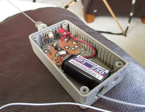
| 5W VLF beacon TX |
OK, I was only testing from the shack to the lounge, but this is a start. TX is 5W from my TDA2003 beacon.
TX frequency 8.976kHz initially with 10wpm CW, 300Hz bandwidth, sending my callsign and a dash. Nothing copied at first using a dummy load but over 70dB over noise using the earth-electrode “antenna” with no attempt to optimise match (fed via the same 3C90 step-up transformer used on 472kHz). With no probe at all (i.e.no RX antenna) the S/N was still some 40dB i.e. very good using the TX into the earth-electrodes.
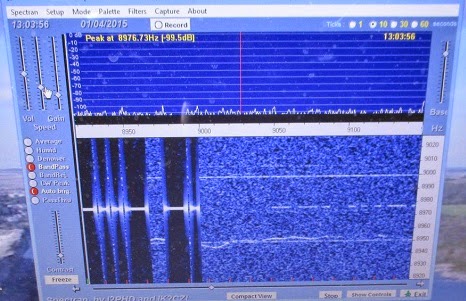 |
| QRSS3 signal received on Spectran (0.37Hz BW) |
Later with QRSS3, a 50 ohm TX dummy load, E-field probe at the RX, I got the signal at 10-20dB S/N. At the RX end I was using my simple E-field probe into a USB soundcard into my Windows 8.1 laptop.
 |
| E-field probe |
The blue photo shows the signal at the RX. The first part shows the TX signal on the earth-electrodes and the second part (weaker) was the signal on the EFP with the TX into a dummy load.
Honestly, this has really exhausted me!
Roger Lapthorn, G3XBM, is a regular contributor to AmateurRadio.com and writes from Cambridge, England.
Grinding quartz and holding a frequency during World War II
I’m a great fan of the Prelinger Archives which is home to so many items like this video I’ve heard about recently from various ham radio email lists.
I like how the components of the earliest electronics and wireless were so basic and ‘natural’. Think of hand made capacitors and resistors using traces of graphite on paper. Valves (or tubes) of course were another story but still capable of being ‘homemade‘.
I love the idea that an accurate, literally rock solid frequency could be achieved using a piece of a very common rock – admittedly a pure piece of quartz cut just so.
This video details the elaborate and meticulous manufacture of quartz crystals during World War 2 by Reeves Sound Laboratories in 1943.
The 41’24” video can also be viewed and downloaded via the Prelinger Archives.
Most of the ‘radio quality’ quartz was mined in Brazil which ceased its neutrality in 1942 and joined the Allies.
The story of quartz crystals during WWII is told in ‘Crystal Clear‘ by Richard J. Thompson Jr. (Wiley) 2011.

“In Crystal Clear, Richard Thompson relates the story of the quartz crystal in World War II, from its early days as a curiosity for amateur radio enthusiasts, to its use by the United States Armed Forces. It follows the intrepid group of scientists and engineers from the Office of the Chief Signal Officer of the U.S. Army as they raced to create an effective quartz crystal unit. They had to find a reliable supply of radio-quality quartz; devise methods to reach, mine, and transport the quartz; find a way to manufacture quartz crystal oscillators rapidly; and then solve the puzzling “ageing problem” that plagued the early units. Ultimately, the development of quartz oscillators became the second largest scientific undertaking in World War II after the Manhattan Project.” (from the book’s blurb)

Reading in your head – the long path to morse code bliss
I’m one of those people who learnt morse code completely the wrong way. Starting off in the seventies with no guide I simply tuned into nightly morse transmissions sent by local hams at a very slow rate. I think they started at 5 words a minute. The main risk there was nodding off between words or impatiently guessing the wrong word.
Contemporary wisdom is that you should start listening at a much faster rate, say 15 or 20 words per minute. This is to prevent you counting dots and dashes in your head, and to make it easier for you to recognise the letters, numbers and even words by their sound.
Learning 15 wpm after mastering say 8 wpm is almost like learning a new language. Students of morse talk of ‘a plateau’ at 10 which is a mighty barrier to progressing up to a more useful conversational speed.
My personal goal is to be able to copy and send at 25 wpm and be able to sustain it over a couple of hours, and to be able to read mostly ‘in my head’, only using pencil and paper for details like names and callsigns.
Now that morse code is no longer compulsory for any ham licenses, surprisingly it seems to be more popular than ever! Especially with those hams who like to use low power to make contacts, or to take the lightest possible transceiver to a remote mountain top as part of the global ‘Summits on the Air‘ activity. Morse gets more mileage than voice per watt, and often these tiny transmitters are only putting out a couple of watts power.
And there’s something delightful in having the skill to read the beeps.
But for me it’s a skill I have to keep working on. I think in my twenties I was quite at ease chattering away at about 12 wpm seemingly for hours on end. Four decades on with a large slab of radio silence in between, I’m quite rusty, even though I know the basics are still there like riding a bike.
I’m a bit wobbly at the paddles, having grown up with the old fashioned straight key (the type you’re likely to have seen in old westerns). But you can feel slow but definite progress from every bit of practice you put in.
A Versatile 630m Antenna

Mark, VA7MM, had come up with a nicely-designed antenna that will serve as his main 630m radiator. Not only that but it can be used on 10m, 15m and 30m and 160m as well!
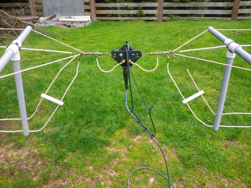
The antenna consists of a mini-flat top dipole, with three resonant dipole legs all terminating at a common feedpoint.

This can be used directly on any of the three high bands. Shorting the end of the coaxial cable, dropping vertically down from the feeedpoint, the dipole feedline becomes the vertical element of a top-loaded 630m 'T' antenna, 100' in the air.
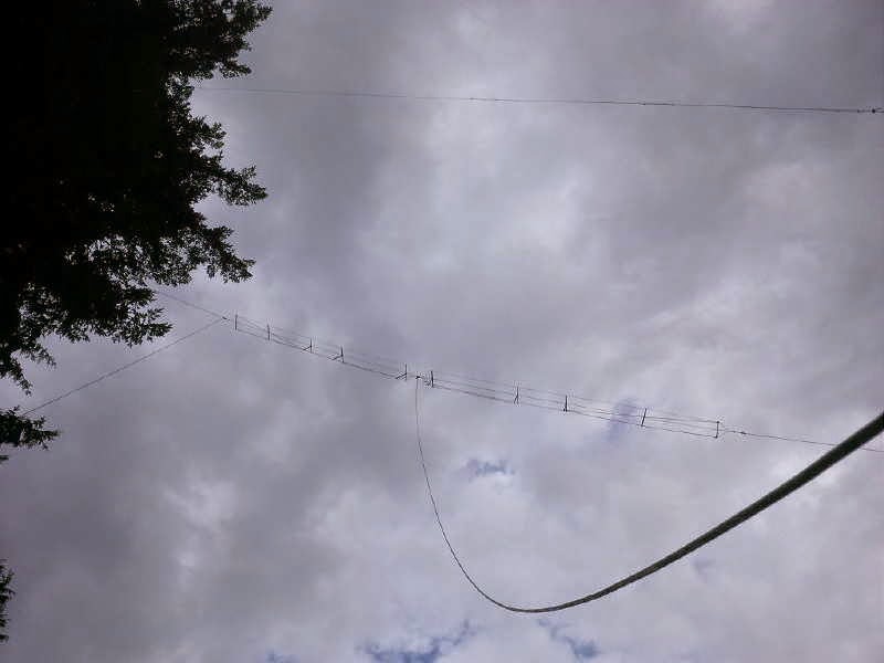
With suitable loading coils and appropriate switching, the 'T' will also be used on 160m, making the versatile antenna work on five different bands ... a nice demonstration of basic antenna principles put into real practice!
Steve McDonald, VE7SL, is a regular contributor to AmateurRadio.com and writes from British Columbia, Canada. Contact him at [email protected].
Inverted High Frequency Loss with LMR-450G
By John ‘Miklor’ K3NXU
PERFORMANCE TESTS – LMR-450G
The recently announced LMR-450G cable has aroused much curiosity since its characteristics have not been collectively available by any one source. By multiple inquiries to several manufactures (only three at this time) and numerous lab tests, we hope to put many of the existing questions to rest.
DESCRIPTION
The physical make up of this cable varies slightly from most conventional RF cables. The center conductor is a semi-stranded copper alloy surrounded by Telfon, which will absorb and distribute cable ‘hot spots’ caused by excessive standing wave. The double silver braid and foil outer coating which provides a 98.6% shield is what the inverted high frequency loss characteristics are attributed. The loss is substantially less as the frequency increases, making this cable especially attractive for UHF, cellular, PCS and microwave applications.

Measuring cable loss under lab conditions
LOSS PER 100′
30 MHz 2.4 db
50 MHz 2.1 db
150 MHz 1.6 db
450 MHz 1.1 db
800 MHz .51 db
1200 MHz .37 db
1950 MHz .31 db
The cable’s most unique property is attributed to the outer jacket material Neo-glow, an RF sensitive composite plastic which will visibly indicate RF ‘hot spots’ in the cable. Adjusting the cable length to the antenna system for the ‘perfect’ impedance match is crucial at high frequency, thus the importance of a low SWR for peak performance.

From 100 Watts and up this cable will brighten up your world.
PROPER INSTALLATION
The low level emission of light from LMR-450G cable can be enhanced by wearing lightly tinted sunglasses with UV protection, which enhances the light radiation from the cable. Select an approximate length of cable needed for the installation which must be multiples of a 1/4 wavelength for the desired frequency. The exact length can be determined by using the formula 467 / Freq (MHz) plus approximately 18 inches.
The initial tests should be run with a 50 ohm dummy load at one end of the cable. With a minimum of 7 watts from the transmitter, you will see a faint glow from the cable indicating the ‘hot spots’ to be eliminated. These are the points along the cable where the RF is at its maximum. It is at these points where the RF connectors should be mounted. Trimming the excess cable may be required at both ends of the cable to produce the most effective match. Use caution not to trim too much cable as the loss characteristics improve with longer cable lengths.
SUMMARY
This could be the beginning of the long awaited high frequency “SUPER” cables. Only available in limited quantities at this time; contact your local cable supplier for more details.

Hans, PD0AC, is a regular contributor to AmateurRadio.com and writes from Almere, The Netherlands. Contact him at [email protected].
 Ham Radio Deluxe |
 W5SWL Electronics |
 Ham Radio Prep |
 KB3IFH QSL Cards  Hip Ham Shirts  HamRadioAuctions HamRadioAuctions Reliance Antennas Reliance Antennas Enigma Shop Enigma Shop |  morseDX  Ni4L Antennas  R&L Electronics R&L Electronics antennas.us antennas.us Ears to Our World Ears to Our World |
- Matt W1MST, Managing Editor
