Posts Tagged ‘630m’
 630m – Locked & Loaded

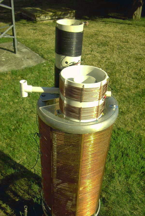
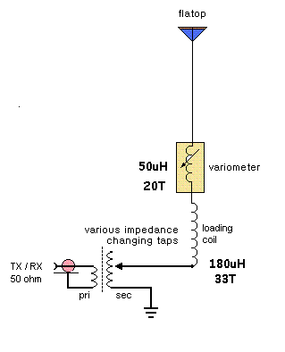
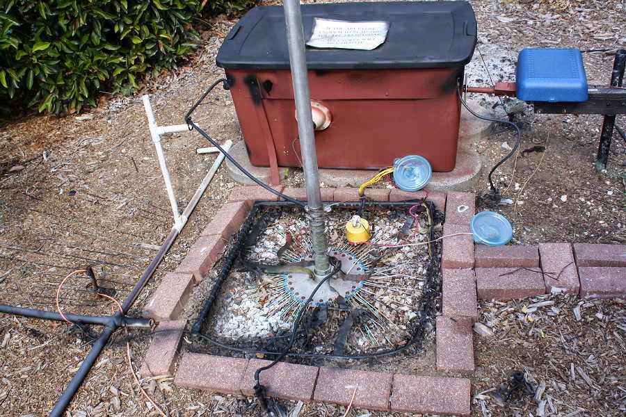
Several hours were spent yesterday finishing off the new 630m antenna matching transformer and installing the new loading coil with built-in variometer.
I decided to remove two turns from the bottom half of the coil, lowering the tuning range from 177-330uH to 165-313uH. Still not ideal but slightly more efficient. In reality, any losses from the variometer inefficiency are minuscule compared to the overall ground-system losses and probably unmeasurable. As it stands, the inverted 'L' resonates on 473kHz with 185uH of inductance and ideally the variometer should be operated closer to its total maximum inductance.
.jpg)
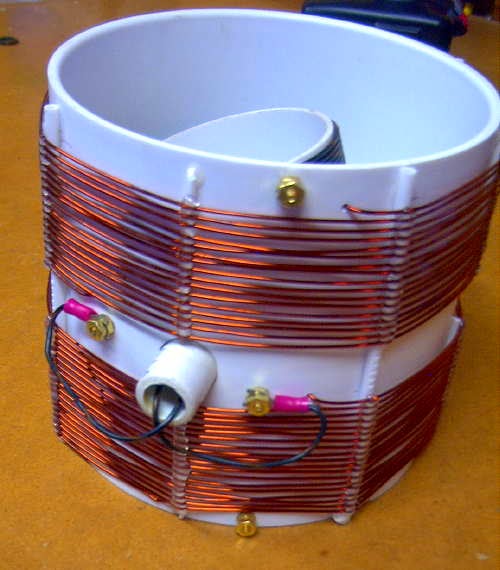
The new coil can be seen mounted on top of the much larger 2200m loading coil, a real monster by comparison. It was removed from one of the local NDB transmitters and saved from going to the scrap yard by an alert technician, who kindly donated it to me when I began operations on 2200m. I can only guess at what this must have cost to purchase when new, as the construction quality is superb.
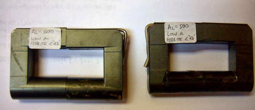
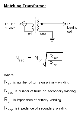
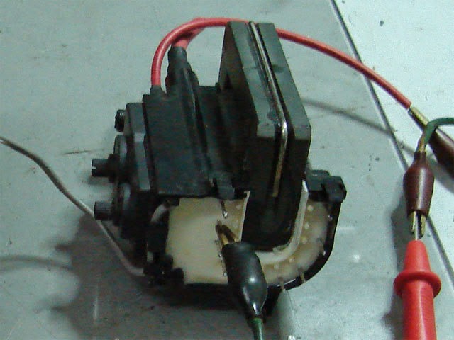
The new matching transformer is similar to the one that works so well on the 2200m system and wound on two TV flyback ferrite cores.
Once everything was cabled-up, I returned to the shack and plugged the coax into the KØLR antenna meter (VFO) and tuned it to 473kHz. I then went back to the variometer and tuned it while watching the meter through the shack window, looking for the sharp rise in current that would indicate resonance. I swept from one end to the other but saw no change! I eventually realized that I had not attached the antenna downlead to the top of the loading coil...duhh!
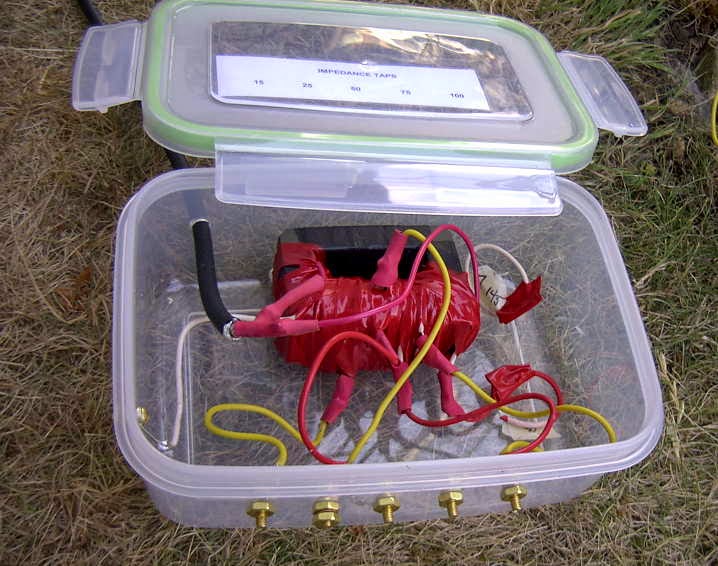
Once in place, the sweet-spot was quickly located and I returned to the shack to switch to the transmitter and scope match. For starters I had set the matching transformer to the 50ohm tap but the Scopematch indicated a resistive impedance of about 25 ohms. Moving to the 25 ohm tap resulted in a perfect match as can be seen here with both the current and voltage waveforms in exact phase and amplitude.

The Scopematch truly makes things easy, once you remember to attach the antenna!
The antenna tuning systems for 2200m and 630m are now separate and independent of each other, each with their own coaxial feedline and tuning system but I really wonder if I'll ever be active at all on 2200m again as there just appears to be no real interest amongst Canadian amateurs in our new 'topband'. It's really a shame since so many people worked very hard to obtain 2200m for Canadian amateurs...for me, its been a wonderful learning-ground for building and experimenting, as is 630m.
With the 630m system all ready to go at maximum EIRP, things are all set for the late October 630m Activity Night (hope you will be there). In the meantime, while awaiting new Canadian activity (come on guys!), I'm open for business.
Anyone wishing to try a two-way crossband contact please let me know. Both myself and VE7BDQ would love to work you!
630m Loading Coil & Variometer Update

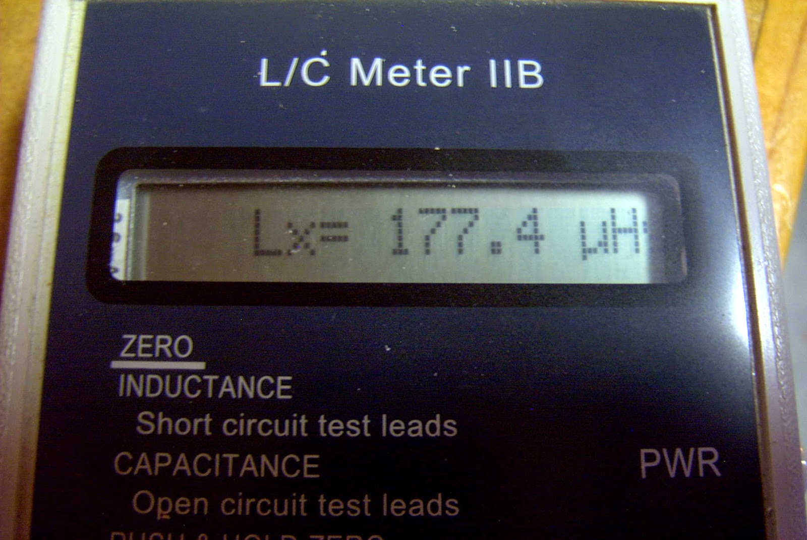
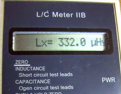
Originally planning for something in the 130-230uH range, the final result produced 177-332uH...certainly more than enough and perhaps a little too much more. I may end up removing a few turns from the main coil as apparently the best variometer efficiency is realised when operated towards the maximum end of inductance, rather than at the low end or when the inner coil is bucking the main coil.

 |
| Source: http://www.alg.myzen.co.uk/radio/136/ant_xformer.htm |
 | ||
| Source: http://www.alg.myzen.co.uk/radio/136/ant_xformer.htm |
 |
| Source: http://leoricksimon.blogspot.ca/2007/05/flyback-driver.html |
A New 630m Loading Coil & Variometer
I've decided, for the time being, to keep my 2200m (136kHz) antenna tuning system separate from the 630m system. This means that I'll need to build a new loading coil, variometer and impedance matching transformer. I'm not really sure why I should maintain the 2200m capability since there is not really much activity here. The only two excuses that I have at present are the fact that it took a heck of a lot of work to get to this point (but it was mostly "fun work") and that the U.S. may be getting the band soon. I'm also not convinced that even if the U.S. does get the band that it would translate into much new activity....so, for the time being, I will keep the system intact.
I've used an online coil calculator to design the coils needed for loading and for the variometer....it will be interesting to see how close the finished values compare with the calculated values. I hope they're not too far off! Here is what the plan calls for:

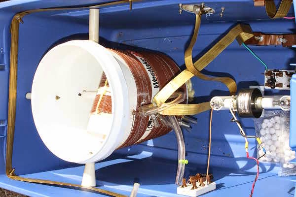
The main loading coil will be built on a low-loss 6" styrene pipe coupler using #16 solid copper transformer wire, spaced at 3mm. The coil will be elevated above the main form by strips of styrene rod that I have filed small notches into, every 3mm. The rod height will be staggered around the form, gradually stepping down one full turn every 360 degrees. Inside the main coil, the smaller variometer coil will be wound with poly-covered #18 stranded wire on a short length 3 1/2" PVC pipe.
Hopefully I'll get something that tunes from 130-230uH, approximately....if so, I'll not only be happy, but really surprised!
Smoke Testing The GW3UEP 630m Transmitter
 |
| Drain (top) vs Gate (lower) on testbed Class-E GW3UEP TX |
I've just completed the Muppet-styled printed circuit version of my previously breadboarded GW3UEP 630m transmitter. The earlier version was built "ugly style" in order to optimize part values and measure circuit parameters.
 |
| Testbed (Ugly-Style) |
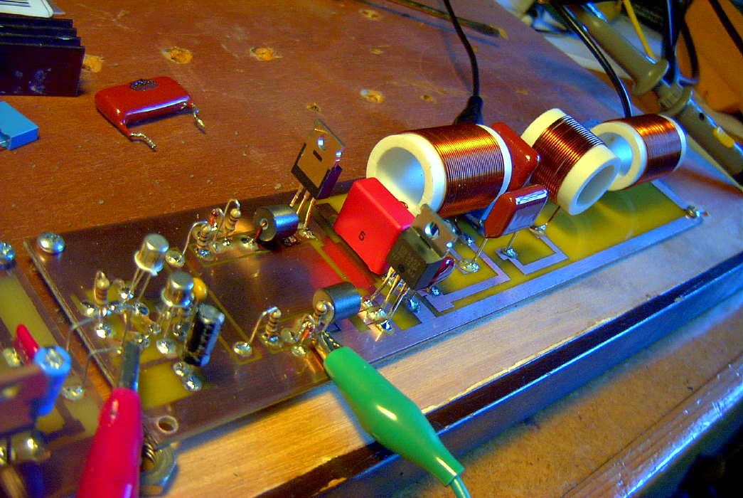 |
| Final Version (Muppet-Style) |
Running the TX at 12.8VDC on the drain(s) at 2.3A produces an input power of 29W. The measured power out, after the LPF, is 23W into a 50 ohm load. This represents an efficiency of 80%. When run in the normal speed CW mode, the FETs run cool enough that they would probably not even need a heatsink but if run in any of the QRSS (long keydown periods) modes, would certainly benefit from heatsinking.
Running the TX at a higher voltage of 22.6VDC (on the amplifier only) yields a current of 4A for an input of 90W. Measured output power is 71W for an efficiency of 79%.
Heatsinking would be required at this power level, even for normal speed CW but the finals seem to run just slightly warm. A larger heatsink or possibly a small fan as well would be required for any QRSS CW modes.
I suspect that the efficiency could be further improved yet with very fine tweaking of the output circuit L/C network but the extra few watts gained would not be significant.
At either power level, this easy-to-build transmitter would make a great "first 630m transmitter" for anyone wanting to get started on our new band.
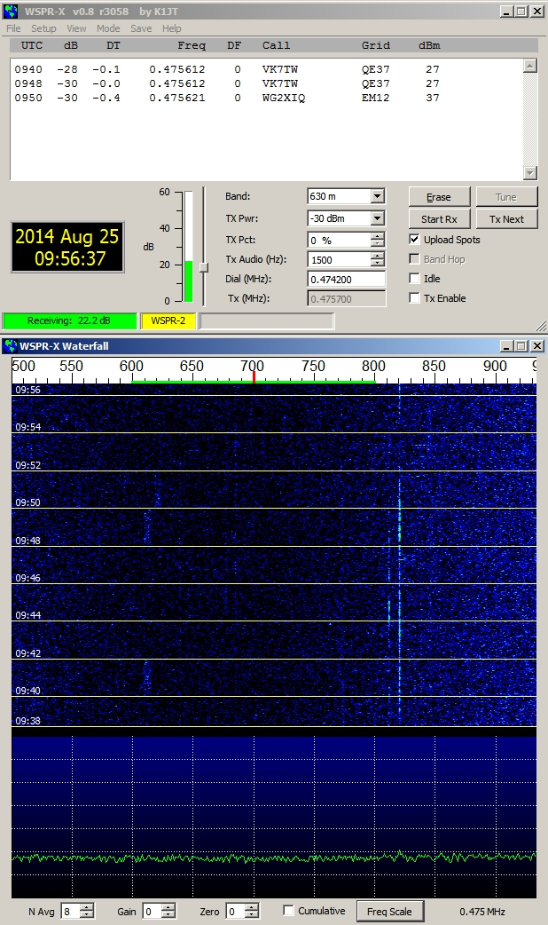
630m Trans-Pacific WSPR
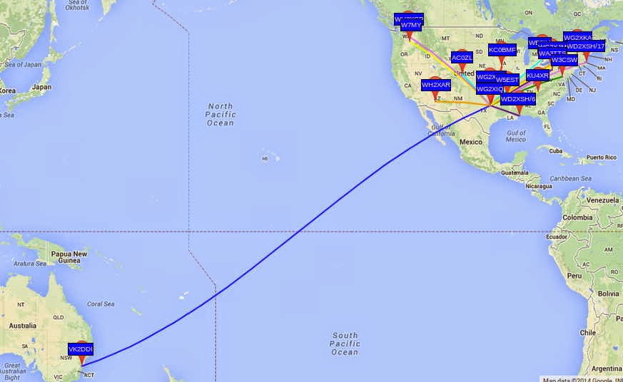 |
| Courtesy: https://www.google.com/maps/ |
This is particularly noteworthy in view of the relatively low power used for John's beacon....around 200W. With the typical backyard antennas being used at these frequencies, efficiencies are very low and John's actual ERP is less than 5W. The transpacific reception of John's signal by VK2DDI confirms what most LF'ers already know....that small suburban lot amateur installations can have positive results on 630m without the need for huge antenna systems.
The WG2XIQ beacon was operating in the WSPR mode, which has become very popular amongst 630m experimenters as well as those just interested in listening-in. WSPR is not a QSO mode but strictly a one-way 'beacon' mode. Although two stations may each spot each other, it is not considered to be a valid two-way QSO. A check of evening WSPR activity will often reveal dozens of stations actively spotting what they are hearing.
Like most LF stations, John's is mostly homebrew.
 |
| WG2XIQ/KB5NJD |
I'll let him describe the details:
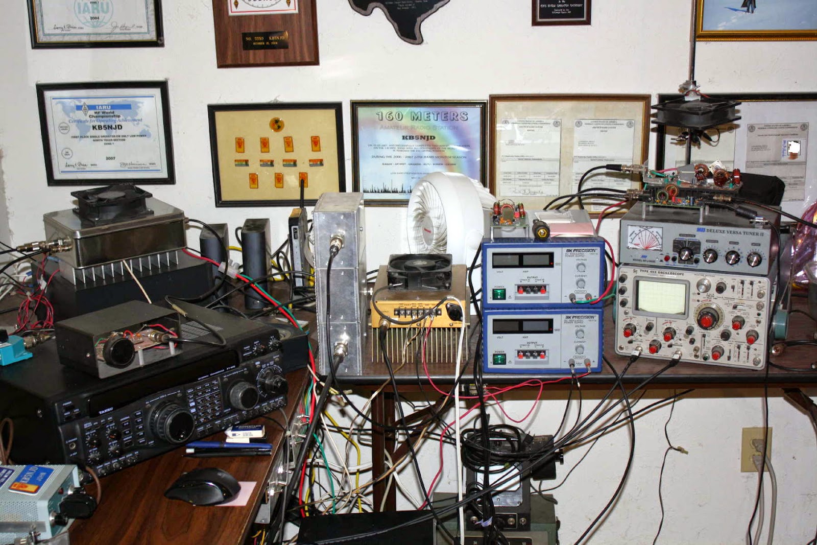
"I have a few ways of making RF in the shack. I can do CW with a very nice waveform using the GW3UEP VFO/Driver coupled with a GW3UEP 100w amp with waveform shaping. The other way is via the MF Solutions transmit downconverter, developed by John Molnar, WA3ETD/WG2XKA. I have two of those boards, one is a backup. I use a GPSDO for the LO and use that signal to drive two parallel GW3UEP amps with max power at 125 watts each. The W1VD Ø degree hybrid combiner brings them together in phase for close to somewhere between 200 and 250 watts TPO depending on how hard I drive and how close I match the TX levels entering the combiner. I filter the output with the W1VD KW LPF that was built by Dave Robinson G4FRE (ex WW2R). I power the amps with a pair of BK Precision 30V 6Amp variable power supplies (variable current limit threshold also). Scope match is used to resonate and match the the impedance. IF Rig on 630m is typically a Yaesu FT920. These days RX antennas are the VE7SL multiturn loop or the TX vertical, both of which have their own merits depending on the conditions at the time."
 |
| John's 630m Vertical |
"Antenna is an 80 foot asymmetric T-top marconi with 100 foot and 200 foot legs....radial system is almost 3 miles of radials connected via various busses. 26 ground rods around the property. I monitor current in the shack and sample via a Bauer current transformer from an AM BC ATU."
 |
| 630m Radial System |
 |
| 630m Antenna Loading Coil & Variometer |
John's system does indeed work well...just last year at this time, his 630m signals were copied by KL7L near Anchorage, Alaska.
Of course, equal credit must be given to VK2DDI for having a system good enough to hear John's signal all the way down on Berry Mountain, New South Wales, Australia! It is there that David has set up a fine LF station, 500m above and overlooking the Tasman Sea...an ideal location for weak-signal LF work.
 | ||||
| VK2DDI - Berry Mountain, NSW |
 | ||
| WG2XIQ Signal As Heard in VK |
David also runs the Berry Mountain Grabber, providing other VK and ZL experimenters a handy way of checking their system progress or propagation conditions.
If you have been doing any WSPR work on HF, you might be surprised at what you can hear down on 630m, even without a dedicated antenna for that band. Surprisingly good results can often be had with a non-resonant antenna as the signal to noise ratio can often be better even though signals may sound weaker. Give it a try and spot what you hear!
If you are interested in learning how to receive WSPR, here is a nice tutorial by ZS6SGM.
Should you be interested in knowing more about obtaining a Part 5 licence to transmit on 630m, John will happily guide you through the process. He can be contacted via email or you can find him hanging-out most nights on the ON4KST kHz (2000-630m) chat page.
To keep on top of what is happening or who is on-the-air, most LF'ers rely on three sources:
- the RSGB LF Group reflector
- the Lowfer list
- the LWCA Message Board
‘CQ Crossband’ – 630m
.jpg) |
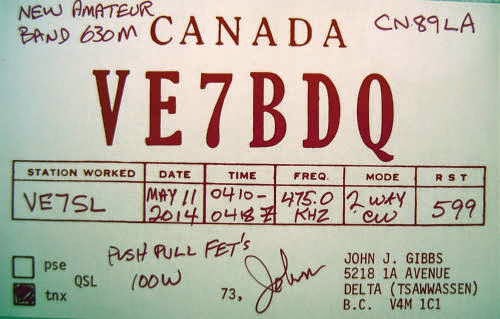
| First 630m contacts |
In early May, VE7BDQ (John) was my first contact on our new 630m amateur band! Soon after, I had QSO #2, with VA7JX (Jack), on Vancouver Island. So far there appears to be only one other station in Canada on the band... VO1NA in Newfoundland!
Where are the rest of the Canadians? It's not too late to be the 1st VE6, VE5, VE4, VE3, VE2 or VE1 on the new band!
Hopefully there will be more stations active before the winter DX season gets underway!
In an attempt to keep my own interest level up as well as trying to get the word out to others about our new band, I've completed crossband contacts with three other VE stations. Two of the contacts were on Vancouver Island....VE7DAY (John) in Campbell River and VA7FC (Perry) in Courtenay. The third station was VE6TA (Grant), near Edmonton, Alberta. A fourth crossband contact was completed when I worked W7WKR (Dick) near Lake Chelan in Washington state. John, VE7BDQ, also completed crossband contacts with VE6TA and W7WKR giving those two stations a 'VE7 two-fer'.


.jpg)
Both John and I would love to do a lot more crossband work, especially with stations in the U.S.A. who presently cannot transmit on the band but may still be very much interested in 630m. A recent overnight beaconing session at 25 watts output clearly indicated that under fairly normal conditions and with a good receiving system on 630m, my normal speed CW signal can cover a wide geographic area during the hours of darkness. Having up to 500 watts of power available for CW, my signals should have good coverage to all of the western and central states at this time of the year.
Such crossband type contacts are perfectly legal between any and all stations in the "amateur radio service" and at one time, this was the only mode available between Europe and North America on the 50MHz band, as this tantalizing review of Cycle 19's amazing propagation explains.
If anyone, anywhere (both U.S. or VE), would be interested in attempting a crossband CW QSO, I would love to try! Please contact me via the comments section below or via e- mail.
I would also be interested in hearing from any Canadians who are planning to get on the new band as I am trying to keep track on my website's LF page.
e-Bay PCB Thermal Transfer Paper
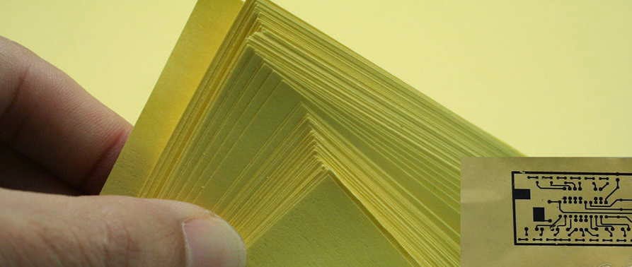 This past weekend I had the first opportunity to try my e-Bay purchased thermal transfer paper. It was to be used in my iron-on PCB work as a hopeful improvement over what I had been using...just ordinary printer paper. Supposedly the shiny photo quality papers were proving to be good performers but are expensive. Some have reported good results with glossy magazine paper but my one experience with that was not a pleasant one. Unknowingly, when I had removed the magazine page, a small amount of the sticky adhesive used in the binding process was still on the sheet. Running it through the printer caused it to melt and smear some of the laser cartridge's toner and for the next several weeks, any printing I did had a slight black streak along one edge...doh!
 My new paper from China (free shipping!) was pretty inexpensive and if it offered even a slight improvement, would be well worthwhile. This first use of the paper would be a circuit board for my earlier test-bed GW3UEP 630m transmitter. I had finished designing a PC pattern for it, using MS Paint, and was anxious to see the results.
 |
| Courtesy: http://www.gw3uep.ukfsn.org/ |
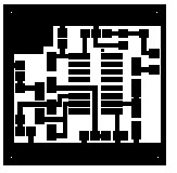
I know that a lot of folks turn up their noses at MS Paint but I have always found it to be a very versatile piece of software and have used it for making PC layouts for many years. I also use it for drawing all of the schematics appearing on my website.
After printing the pattern (printer set for maximum resolution and darkest print) and ironing-on the pattern , I allowed the board to cool for several minutes before immersing it, along with the now firmly attached yellow paper, into cold water. The first thing I noticed was how easily the paper came away from the board. It actually 'un-peeled', much like a good quality price tag sticker...you know.... the ones that don't take forever and come off in tiny bits and pieces. It peeled off smoothly with no paper residue left on the board. This was a huge improvement already. There were just a few traces of toner left on the paper as almost all had been transferred to the board.
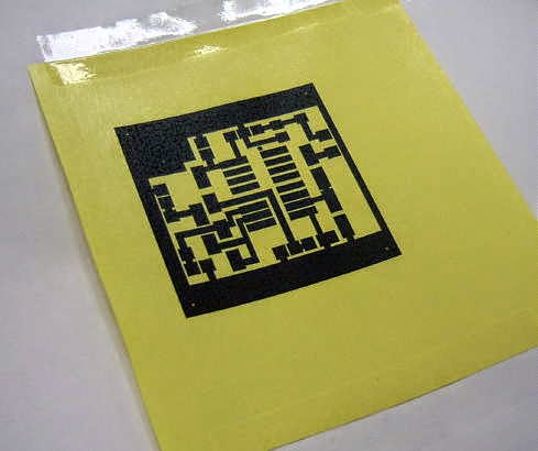 Once dried, a close examination revealed that I had pressed a little too hard with the iron and there was some evidence of 'squeeze-out' along the edges of some lines. I also found one or two very small thinner areas that probably required going over with a permanent-ink black marker pen just to make sure that those spots did not get etched. Over all I was extremely pleased with the paper and will be using it from now on.
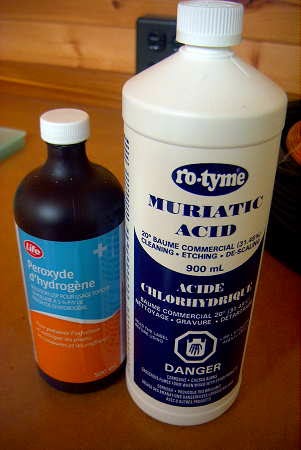
Another recent change in my PC etching regime has been a switch from the old Ferric Chloride standby to a combination of Hydrogen Peroxide and Muriatic acid. Not only does it seem to etch more cleanly (no undercutting) but it also etches very quickly and without any solution warming needed. This board was completely etched in just over 4 minutes.

The chemicals used in this method are inexpensive and are readily available at the drugstore and at the hardware store. There are numerous web-descriptions of this particular etching process but this site seems to cover the basics nicely.
The completed board turned out as shown here:
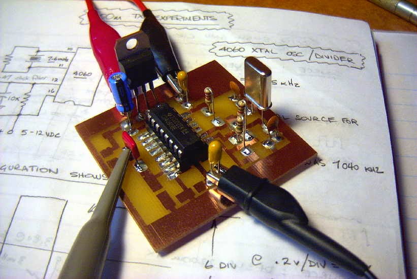
The CD4060 not only functions as a crystal oscillator but also as a versatile frequency divider. As well as fundamental frequency output, ten different 'divide-by' functions are available depending in which output pin is chosen. These range from divide-by 16,384 to divide-by 16. This circuit uses the latter, dividing the 7.6 MHz crystal down to 475 kHz at pin 7.

In summary, I can highly recommend the e-Bay yellow thermal transfer paper when used for this method of making PCB's and is much cheaper than buying photo-quality printing paper.


