Posts Tagged ‘630m’
 630m And Recent Geomagnetic Activity

High levels of geomagnetic activity have usually, but not always, been the kiss-off-death for LF/MF propagation.
These past few months have seen fairly regular field disturbances, often pushing the K index to a level '5' or higher. However, while usually attenuating the east-west and northerly polar paths, the Trans-Pacific path often seems to benefit from these events ... particularly last night.
Perhaps it is related to the equinox's normal preference for this path or maybe the goop the sun is sending us at this point in the cycle is different or not as energetic as it is at mid-cycle. Nevertheless it's really encouraging to see that not all disturbances are detrimental to LF propagation.
For a daily summary of all overnight activity and much more, see KB5NJD's '630m Daily Reports'.
The WSPRnet map reproduced below shows the extent of reception during my own overnight WSPR 630m beaconing session. Missing are many of the normal spots from the eastern provinces and east coast states, indicating the attenuation on this path. Everything else seems enhanced.
 |
| courtesy: WSPRnet |
The path to down under, in-spite of my obstruction in that direction, perked-up as well, with VK4YB decoded here 19 times as well as VK3ELV's 150W and inverted-L near Wangaratta, Victoria.
13:56 VK4YB 0.4756 -28 QG62ku 11820
13:50 VK4YB 0.4756 -28 QG62ku 11820
13:44 VK4YB 0.4756 -24 QG62ku 11820
13:40 VK4YB 0.4756 -24 QG62ku 11820
13:30 VK4YB 0.4756 -27 QG62ku 11820
13:24 VK4YB 0.4756 -20 QG62ku 11820
13:18 VK4YB 0.4756 -24 QG62ku 11820
13:12 VK4YB 0.4756 -22 QG62ku 11820
12:42 VK4YB 0.4756 -26 QG62ku 11820
12:14 VK4YB 0.4756 -20 QG62ku 11820
12:02 VK4YB 0.4756 -23 QG62ku 11820
11:58 VK4YB 0.4756 -25 QG62ku 11820
11:52 VK4YB 0.4756 -25 QG62ku 11820
11:40 VK4YB 0.4756 -29 QG62ku 11820
11:32 VK4YB 0.4756 -26 QG62ku 11820
11:24 VK4YB 0.4756 -25 QG62ku 11820
11:12 VK4YB 0.4756 -22 QG62ku 11820
10:56 VK4YB 0.4756 -26 QG62ku 11820
10:54 VK4YB 0.4756 -25 QG62ku 11820
Merv, WH2XCR in Hawaii, was spotted here 56 times, with numerous transmissions at 'easy CW' levels. He even spotted me twice, with his 80m dipole, presently laying on the ground!
It was also encouraging to see 21 spots from Eden, ZF1EJ in the Cayman Islands, with several at CW levels.
The following stations all uploaded spots of my overnight WSPR signals, as nightly activity continues to grow with the DX season now at the doorstep. Given equal ERP, most of these stations would be workable on either CW or on JT9.
WH2XGP DN07dg 319 122
WG2XSV CN85sr 353 169
WI2XJQ CN87ts 138 150
NO1D DM34tn 1825 147
N3IZN/RX DM13ji 1796 161
WW6D CM88pl 1155 177
VE7CNF CN89ng 55 33
VA7MM CN89og 59 38
WE2XPQ BP51ip 2151 321
W5EMC EM10cl 2963 124
K5ACL EM10bd 2987 125
WG2XXM EM15lj 2610 115
ZF1EJ/1 EK99ig 4977 116
KE7LGT DN26xm 739 107
W3PM EM64or 3365 104
ZF1EJ EK99ig 4977 116
VE7KPB DN29cm 550 79
KU7Z DN41af 1227 129
WH2XCR BL11je 4295 236
KB0BRY EN17nc 1966 86
WD2XSH/20 CN83 598 178
WG2XIQ EM12 2841 120
WE4X EM65ut 3326 102
VE7BDQ CN89la 26 44
KB7W CN93jx 565 163
W6LEO DN17oq 498 103
WH2XAR DM33vp 1924 147
As interest in 630m continues to expand, many U.S. amateurs are already building their stations so they will be ready to go when the word finally comes. I suspect that 630m may soon sound like a small slice of 40m on a busy night ... will you be ready?
 First VK-VE 630m Contact!
 |
| courtesy: https://www.google.ca/maps |
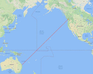
Shortly before sunrise yesterday morning, VK4YB (Roger) and I were able to work each other on 630m ... 475.300 kHz to be exact!
This is the first-ever QSO between North America and Australia on the relatively new 630m MF band. As well, at 11,802km, it presently represents the furthest two-way contact on this band, worldwide ... but I don't expect this record will last very long once the U.S. gets the band as I believe Roger's fine station is very capable of reaching much further afield.
Our contact on JT9, the WSPR QSO mode, was made at 1319Z, about 30 minutes before my local sunrise with the sky surprisingly bright. Blog readers will know that Roger and I have been carefully watching the pre-dawn Trans-Pacific propagation path for the last week. I have been checking-in with him via the ON4KST LF/MF chat page every morning at around 0345 local time at which point a decision is made ... "get out of bed and head for the shack" or "go back to sleep". Each morning's (or in Roger's case, each evening's) propagation quality is assigned a code number by Roger, based upon what he has been hearing during the early evening hours ... a '6' or below is 'sleep-time', a '7' is a 'you decide' while an '8' or above is 'get your butt moving'.
Yesterday, Roger issued a 'code 7' but as I joked with him later, I think he tricked me as it seemed more like a '6.5' from this end! Trans-Pacific conditions were very good about 500 miles to my south but seemed to drop-off quickly much further to the north. I also need to get over a significant obstruction immediately to the SW of me and in line with Roger. That's me directly at the base of the hill on the right while the remaining peaks are on nearby Saltspring Island and then Vancouver Island before reaching the open Pacific.
 |
| courtesy: http://www.heywhatsthat.com/profiler.html |
I believe this requires some enhancement of high-angle arrival (and departure) which often occurs around dawn due to a short period of ionospheric 'tilting'. This is often noted by topband operators near their local sunrise, who regularly observe stronger signals on low (cloud-warming) dipoles than they do on their normal large (low-angle) verticals or beverage antennas.
We enjoyed significantly stronger conditions a week ago, but unlike Thursday when I could run at full 5W EIRP, I was only able to generate a little less than 1W EIRP at the time. So far, this week, conditions have been improving steadily each day, from a 'code 3' to a 'code 7'. Hopefully they will continue to improve and we can do it all over again sometime soon.
With my new antenna / transverter / amplifier relay control box working nicely, it seems that Roger and I can now fully take advantage of TP propagation from 'mediocre' to 'excellent' but we have yet to see just how good it can get.
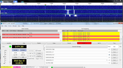 |
| Roger's signal is at +1100Hz |
It is hoped that our contact will inspire new interest among amateurs worldwide and particularly in North America. If you are planning a station, it seems that the main mode of two-way communications will be CW or JT9 ... a simple transverter would allow both modes as well as the use of the WSPR beacon mode. More information may be found here as well as in earlier 630m blogs.
See also: http://www.arrl.org/news/a-record-breaker-on-630-meters
 Transverter-Amp-Antenna Relay Control Box

As mentioned in my last blog, using a transverter to drive a separate amplifier requires some method of switching system in order to automatically handle the antenna, transverter and amplifier input / output ports. To run a relay switching system in the WSPR or JT-9 modes requires that the switching be controlled by the transceiver's PTT line which in turn is controlled by the WSPR software. Using VOX keying is out of the question as it causes the relays to be 'hot-switched' and with higher power will eventually lead to their demise.
For many years I managed PTT line control via my laptop's comm port but these are now things of the past, requiring switching to be done via the USB port. There are many commercial products available that will do this nicely as well as handle the audio feed from radio to computer and vice-versa, but I found that my homebrew version worked just fine. Making it work via the USB port however required a serial-to-usb converter. This was described here, in an earlier blog and for the few dollars invested has proven to be a very reliable interface.
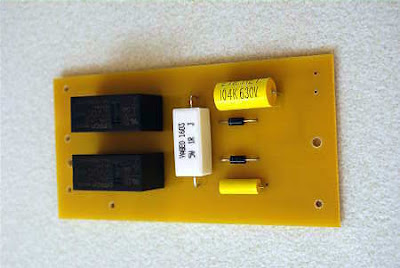
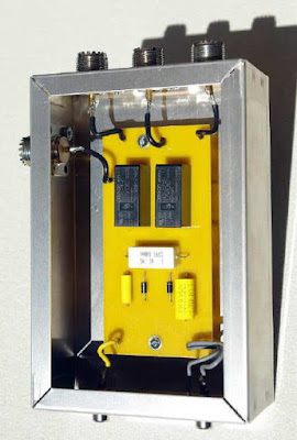
The schematic of the switching control unit is shown below. It uses two inexpensive OMRON G2RL-1-E DC12 relays purchased from Digikey. Although not coaxial, the $3.09 (U.S.) relay will easily handle a kilowatt as decribed by W6PQL. These relays have large contacts, rated at 16A. I added a few extra components that absorb any relay switching transients as well as remove any RF on the control lines.
 |
| Relay Control Unit |
 |
| Keying Line Damper: courtesy: KK5DR |
I must say a few words about Digikey's service. I really am amazed at what a superb job they do in supplying hobbyists with small orders. So many companies nowadays cannot be bothered with such things or demand a large minimum order for the privilege of handling your purchase! From what I can tell, Digikey bends over backwards to help out the little guy, with no minimums as well as dirt-cheap, fast shipping. Living in Canada, I'm used to U.S. dealers making me jump hoops to place an order, only to find out that the cost of shipping is often prohibitively high or they ship only via UPS which I will not accept.
I placed a small two-page order with Digikey via their excellent web site on a Tuesday afternoon. On Friday morning, there was a knock at my door at 0800 hours ... it was a courier service delivering my parts! To put this in context, I live on a small island in the middle of Georgia Strait, accessible only by air or by ferry. To me this service is incredible and the cost of postage was only $6.00 (U.S.). I really have no idea how they do this but they obviously have put into operation a very efficient system ... hats off to them and their skilled management that has figured this all out. A few years ago I sent in orders to both Digikey and to Mouser, each within an hour of each other. Like my recent order, the Digikey parts arrived in just a few days while the Mouser parts took over three weeks ... perhaps things have changed since then but this is the reason I use and recommend Digikey whenever I can.
Once I had the needed parts, I quickly built a PCB for the switcher and put it together in a day so that I might begin 630m skeds with VK4YB as soon as possible.
If you would like a full-size layout suitable for the iron-on toner PCB construction method, I'll be happy to send you one via email.
The first test run with VK4YB at 0300 local time proved problematic. When I fired up at full ERP, I immediately saw some output instability on the scopematch screen. Before I could shutdown however, I had blown a FET in the amplifier, shutting me down and sending me back to bed to worry about the situation.
Having had time to think about the problem made me suspect something in the new relay changeover unit since that was the only new variable in the system. I suspected that perhaps the relays were not fully seated before being hit with full RF output and the possible hot-switching had caused enough short-lived SWR to take out the very reactance-sensitive FET final. In many years of operation with the amplifier, this was the first blown FET I have had. When I built it, I made sure that the FETS would be easily accessible (see below) should such an occasion arise ... unlike my initial transmitter, where replacing a FET was a nightmare.
Fortunately, when FETs go south on a push-pull amplifier, only one FET will blow ... whichever one was conducting at the time, thus preserving the remaining FET. I flipped a coin and unsoldered the source lead of the left hand FET and measured it. Sure enough it had a drain-to-source short. My day was off to a better start. Once replaced, I set out to determine what had caused it to blow in the middle of the night.
Since I didn't want to blow another FET, I could only 'key-up' in very short bursts and see if the instability was still present. I put the amplifier on a dummy load and everything seemed normal but when put onto the antenna, it reappeared. Suspecting an arc in the loading coil, I checked it carefully. I indeed did find a charred blackened section near the top high-voltage end of the coil but that could have been a short-lived event from the past as I'm sure small crawly things often meet their demise between the windings without causing any problems other than a quick puff of smoke or a short-lived arc to the PVC coil form.
After cleaning the coil and removing any carbon paths as well as giving it a few coats of varnish, I was hopeful that the problem would be gone ... but no, the scopematch indicated it was still misbehaving. As well, I could hear a weak but audible high-pitched oscillation coming from somewhere in the amplifier's circuitry. I suspected that it came from one of the output transformers but with the fan noise it was impossible to accurately locate the source of the rogue 'squeal' when briefly keying-up.
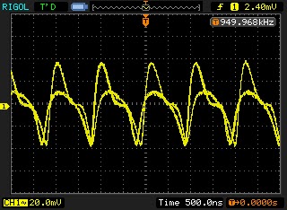
Fast forward several hours of pulling out what was left of my hair and I was no further ahead. The amp continued to work fine at high power, via the new relay system, into my dummy load but into the perfectly matched antenna, the problem remained. It was at this point that I decided to look at the input signal from the doubler, a nice squarewave at 950kHz for the amp's divide-by-two input chip. The scope instantly indicated a dual squarewave with more than one frequency present!
 |
| Recently built W1VD 'Frequency Doubler' |
It looked like the doubler was not getting enough 475kHz input to actually double properly and its output was a mixture of 950 and (mostly) 475kHz. The amp's divide-by-two input would then try and turn this into a mixture of 475 and (mostly) 237 kHz which the highly-tuned antenna system would balk at, producing the unwanted FET-killing reactance. Being passive and none-reactive, the dummy load was quite happy to take the signal all day long if I let it.
With the mystery solved, full ERP beaconing and scheduling with VK4YB has begun once again, but the TransPacific path has been stingy for the past few mornings ... hopefully this will change now that I'm ready again, barring any further complications.
 630m Early Morning Skeds

This past week I was eventually able to mate my W1VD frequency doubler with my 630m FET amplifier and run some higher powered tests on 630m WSPR and JT9 modes.
Up until this time, I have been limited to about 1/2 W EIRP but using the amplifier allows me to get to the 5W EIRP limit. I have been using the VK4YB transverter's 475kHz reduced output of 1W and driving the doubler previously built as part of a transverter project. The doubler produces a nice 950kHz squarewave to drive my amplifier's divide-by-two flip-flop input circuit which in turn produces the dual antiphase outputs needed to drive the push-pull switching FETs in the final amplifier. Being a linear transverter, when used alone at 70W, it will run any mode that the IC756 ProIII will produce such as SSB, WSPR etc, but my switching FET amplifier is class-D, non-linear, which limits it to non-linear modes such as CW, WSPR and JT-9, the most popular modes on 630m.
A few days ago, VK4YB and I ran our first 630m sked on JT9 as conditions looked favorable. Unfortunately, this was before I had my transverter / antenna switching system completed so I was limited to the barefoot transverter at ~ 1/2W EIRP. Using a transverter to drive an external amplifier means the antenna must be switched between the amplifier output and the transverter input in addition to switching the transverter's output between the antenna and the amplifiers input. I'll post details of my switching system, and inexpensive but power-capable relays, in an upcoming blog as there are probably many 630m operators planning on doing something similar.
Thanks to Roger's huge antenna, his 90W signal was making it through well enough on this end but he was not able to decode anything from me.
1109 -26 0.3 1098 @ VE7SL VK4YB QG62
1111 -28 0.3 1098 @ VE7SL VK4YB QG62
1147 -24 0.1 1100 @ VE7SL VK4YB QG62
1149 -27 0.1 1100 @ VE7SL VK4YB QG62
1153 -27 0.1 1100 @ VE7SL VK4YB QG62
1159 -26 0.1 1100 @ VE7SL VK4YB QG62
1209 -26 0.0 1100 @ VE7SL VK4YB QG62
1225 -25 0.1 1100 @ VE7SL VK4YB QG62
1227 -26 -0.0 1100 @ VE7SL VK4YB QG62
1229 -24 0.1 1100 @ VE7SL VK4YB QG62
1239 -23 0.1 1100 @ VE7SL VK4YB QG62
1247 -26 0.0 1100 @ VE7SL VK4YB QG62
1249 -26 0.1 1100 @ VE7SL VK4YB QG62
1253 -23 0.1 1100 @ VE7SL VK4YB QG62
1255 -28 0.1 1100 @ VE7SL VK4YB QG62
1257 -26 0.1 1100 @ VE7SL VK4YB QG62
1303 -27 0.2 1100 @ VE7SL VK4YB QG62
1305 -23 -0.1 1100 @ VE7SL VK4YB QG62
1307 -25 -0.1 1100 @ VE7SL VK4YB QG62
1309 -23 -0.1 1100 @ VE7SL VK4YB QG62
1313 -25 0.0 1100 @ VE7SL VK4YB QG62
1319 -27 0.0 1100 @ VE7SL VK4YB QG62
1323 -22 0.1 1100 @ VE7SL VK4YB QG62
1325 -25 -0.1 1100 @ VE7SL VK4YB QG62
1327 -24 0.0 1100 @ VE7SL VK4YB QG62
1329 -25 0.0 1100 @ VE7SL VK4YB QG62
My location on the 'wrong' side of Mayne Island requires me to fire directly into a very nearby 600' hilltop, directly in Roger's path.
 |
| I'm at the base of the hill on the far right. The large mountains are on Vancouver Island and then open Pacfic. |
| VE7SL | 0.475633 | -25 | CN88iu | 5 | VK4YB | QG62ku | 11820 | |||
| VE7SL | 0.475633 | -26 | CN88iu | 5 | VK4YB | QG62ku | 11820 | |||
| VE7SL | 0.475632 | -23 | CN88iu | 5 | VK4YB | QG62ku | 11820 | |||
| VE7SL | 0.475632 | -26 | CN88iu | 5 | VK4YB | QG62ku | 11820 | |||
| VE7SL | 0.475632 | -30 | CN88iu | 5 | VK4YB | QG62ku | 11820 | |||
| VE7SL | 0.475634 | -28 | CN88iu | 5 | VK4YB | QG62ku | 11820 | |||
| VE7SL | 0.475634 | -30 | CN88iu | 5 | VK4YB | QG62ku | 11820 | |||
| VE7SL | 0.475634 | -30 | CN88iu | 5 | VK4YB | QG62ku | 11820 | |||
| VE7SL | 0.475633 | -28 | CN88iu | 5 | VK4YB | QG62ku | 11820 | |||
| VE7SL | 0.475633 | -29 | CN88iu | 5 | VK4YB | QG62ku | 11820 | |||
| VE7SL | 0.475633 | -27 | CN88iu | 5 | VK4YB | QG62ku | 11820 | |||
| VE7SL | 0.475632 | -28 | CN88iu | 5 | VK4YB | QG62ku | 11820 | |||
| VE7SL | 0.475630 | -28 | CN88iu | 5 | VK4YB | QG62ku | 11820 | |||
| VE7SL | 0.475629 | -29 | CN88iu | 5 | VK4YB | QG62ku | 11820 | |||
| VE7SL | 0.475629 | -31 | CN88iu | 5 | VK4YB | QG62ku | 11820 | |||
| VE7SL | 0.475629 | -30 | CN88iu | 5 | VK4YB | QG62ku | 11820 |
With the antenna / transverter / amplifier switching unit complete, Roger and I will continue to watch band conditions favorable to the Trans-Pacific path and hopefully exchange signals sometime this fall before the path disappears until next spring. For Roger, near Brisbane, the path peaks for him in the late evening while for me, it means crawling out of bed at 0330 local time to check the prop, hoping to find good signals from down under ... working VK on 630m would be well worth losing a few hours of nightly sleep!
 September Prop Awakens

As our sunsets start to come earlier and dawn arrives later and later, the sun's accelerated southerly excursion has brought sudden changes to 630m propagation.
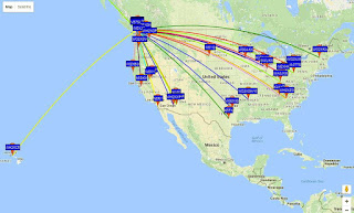
This past weekend's CLE activity saw universally poor propagation as well as weather related QRN from lightning ... but as usual at this time of the year, things can change rapidly. Wednesday's overnight map of my own 630m WSPR activity illustrates why September propagation on LF and MF can often be spectacular and this is with just 65 watts total power output:
 |
| courtesy: http://wsprnet.org/drupal/ |
Among other things, the map indicates the growing interest among U.S. amateurs in the 630m band. Hopefully they won't have to wait too much longer, although I seem to be saying this more often than I would like to. It is of interest to note that even though these were WSPR reports, signal levels at most reporting stations were either into the 'audible CW' levels or at 'JT9 workable' levels ... all stations should be workable once the 630m ham band becomes a reality for all North Americans. Midwinter conditions over the next several years should see an abundance of transcontinental contacts on both CW and on JT9!
The east-west path is the bread and butter direction for interesting possibilities, when it comes to those of us in VE7 land. Normally it only really sets in when geomagnetic conditions are quiet but, as a result of coronal hole streaming, this week's geomagnetic field has been anything but quiet. As John Langridge, KB5NJD / WG2XIQ reported today in his invaluable '630m daily reports':
The geomagnetic field was extremely active, with many reporting periods at storm levels. The Bz is pointing to the South and solar wind velocities are very high, peaking at 700 km/s. This event is significant and I am just glad to see that it is helping and not hurting propagation. When will the bottom drop out? Clearly there is a lot going on here that we do not understand.
With stormy conditions continuing throughout the week, Friday's path to down-under enjoyed some enhancement as well, not unusual when the east-west path is disturbed. VK4YB's 90 watt signal was widely heard by several VE7's (VE7CNF, VA7MM and VE7BDQ) in the predawn hour, as Roger's signal peaked up briefly for several WSPR decodes.
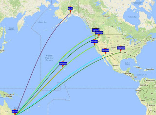 |
| courtesy: http://wsprnet.org/drupal/ |
As the coronal hole streaming continues, this morning's path to VK seemed even better along with a new antenna at VK4YB favoring the northwest:
12:24 VK4YB 0.475622 -21 VE7BDQ 11844 km
12:12 VK4YB 0.475621 -22 VE7BDQ 11844 km
12:08 VK4YB 0.475622 -17 VE7BDQ 11844 km
11:04 VK4YB 0.475622 -24 VE7BDQ 11844 km
11:02 VK4YB 0.475623 -22 VE7BDQ 11844 km
10:54 VK4YB 0.475623 -22 VE7BDQ 11844 km
12:28 VK4YB 0.475626 -21 VE7SL 11820 km
12:24 VK4YB 0.475625 -23 VE7SL 11820 km
11:54 VK4YB 0.475623 -25 VE7SL 11820 km
11:04 VK4YB 0.475623 -23 VE7SL 11820 km
11:02 VK4YB 0.475625 -26 VE7SL 11820 km
10:54 VK4YB 0.475626 -21 VE7SL 11820 km
11:22 VK4YB 0.475614 -28 VA7MM 11872 km
11:04 VK4YB 0.475614 -28 VA7MM 11872 km
11:02 VK4YB 0.475615 -33 VA7MM 11872 km
10:54 VK4YB 0.475615 -26 VA7MM 11872 km
I should mention that the other VE7 stations are all operating from noisy suburbs near Vancouver ... clearly fine examples of what can be done on 630m under less than ideal operating conditions and by paying close attention to system optimization. Please don't let living in the city stop you from enjoying the mysteries and challenges that our latest ham band has to offer ... as mentioned earlier, there is still much to be learned about using this band at amateur radio power levels and small backyard antennas. How exciting is that!
 Summer SMT Project
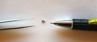
Over the past week, I've been playing with my 630m transverter summer project.
It's not the normal type of transverter that would produce a signal on 630m (~475kHz) but rather, one that will produce a signal on twice this frequency. My630m amplifier, using switching FETs, was designed and built with a 'divide-by-two' input circuit, to allow for greater frequency resolution when first constructed as a 2200m system. I really don't want to modify the transmitter and prefer just to be able to unplug my DDS and plug-in the transverter, allowing me to run WSPR, JT9 and several other digital modes when needed.
So far I've not been able to get the transverter to produce the desired low voltage 950kHz squarewave output, although I'm closer than when I began the troubleshooting.
My circuit is basically a G3XBM 630m transverter, without the FET final amplifier. Instead, the driver feeds a full-wave rectifier frequency doubler for 630m, designed and published a few years ago by Jay, W1VD. Although I can get a squarewave end result, I think harmonics creeping into the process earlier down the mixing chain are causing non-symmetry in the output.
 |
| 3.2MHz signal out of oscillator buffer stage |
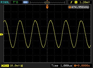 | |||
| 475 kHz signal out of mixer stage |
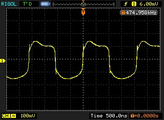 |
| Signal out of 'squarer' stage |
 |
| Signal out of full-wave bridge |
 |
| Signal out of LPF |
 |
| Asymmetrical squarewave from 4046 output |
I've tried a 3-section LPF with a cutoff of ~600kHz between the mixer output and the next stage, trying to knock down the 'sum' frequency of 6.875MHz and any crystal harmonics but have since replaced this with a 630m diplexer at the mixer output to pass anything below 1MHz to the squarer and anything above 1.5MHz to ground. I'll keep playing with it ... until it works as it should or I have no hair left to pull out. I may also just rebuild the circuit, Manhattan-style, with normal sized parts, making it much easier to change or modify as I need. The scope grabs shown above are with the diplexer in place at the mixer output. It seems like something in the full-wave frequency doubler is amiss. I've looked at T1, the bifilar transformer several times but don't see anything odd but that's the stage where things seem to go south. Maybe it's an impedance matching-thing, something I'm yet uncomfortable with when it comes to properly matching various stages.
I also now realize that the section of transverter I have chosen will require post-mixer filtering, not shown in the schematic. Not using the last stage (FET PA) and its associated filtering, has no doubt caused more harmonics to appear in the output than anticipated. If I redesign and rebuild, I will add an LPF after the crystal oscillator as well as at the RF input port and pay more attention to post-mixer filtering.
Another route to try, rather than the W1VD doubler, may be this 4069 IC doubler or a similar 4011 doubler.
Although the project outcomes have not yet been achieved, the process has been a positive one in a couple of respects and well worth the time spent so far.
I have learned that working with the 1206-sized SMT parts is much easier than suspected and in fact, populating the board with these tiny parts was a lot of fun. The 1206-sized parts are at the 'large' end of the SMT size-spectrum ... rest assured I won't be going any smaller, at least for now.
The other positive outcome was knowing that my PCB design process can work well with the narrower lines, pads and much smaller IC footprints. I still design my boards using MS Paint and have always been happy with the ease at which it works. I know many might scoff at MS Paint but it really is a very versatile little program, with a short learning curve, unlike many of the more sophisticated PCB design programs.
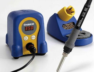
And one more positive outcome. I used the project as an excuse to purchase a new soldering station ... one that I had been lusting over for a few years as it is very SMT-friendly compared to my old Weller clunker. It also has an electrically isolated tip, unlike my Weller. The Hakko FX-888D turned out to be everything I had hoped and was no doubt part of the reason that I found the SMT process so enjoyable.
 |
| Add caption |
 The New VK4YB 630m Transverter
For the past several months I have been beaconing overnight on 630m WSPR mode. I've been using a new transverter designed by Roger Croft (VK4YB) and Ralph Loveday, in Queensland, Australia. One unit was sent to me for beta testing and I have been hammering it as hard as I can ever since setting it up in the spring ... no problems have been experienced after several months of 12 hour nightly beaconing punishment. Nightly signal reports often range from Hawaii / Alaska and eastward to New England ... all during the 'not so good' summer band conditions.
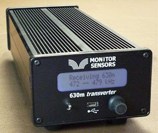
Now that beta testing is complete, production units are now ready for distribution from Monitor Sensors, a family environmental-sensor manufacturing company of which Roger is Governing Director.
The introduction of the VK4YB 630m Transverter presents another new option for those wishing to get on the band, or in the case of American amateurs, to get prepared for the band ... soon expected to be implemented in the U.S.
When I first started using the test unit provided, I was immediately impressed with how simple it was to set up and to get operational. It sits inconspicuously beside the main station's transceiver, taking up less space than the typical station speaker unit.
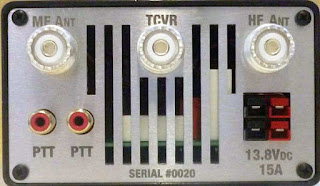
One usually associates 'transverter' operation with a rat's-nest of cabling or re-cabling to accommodate the new addition. The transverter arrived with all necessary cabling, even a nice Anderson power pole connector to connect the user-supplied 12V power source. A second pair of 12V contacts is also available for sharing with other station needs. One feature that I quickly appreciated was the dual RCA jack on the rear panel for controlling the transverter's PTT keying line. With my transceiver's PTT line already being used for another purpose, it was simply a matter of plugging-in (cable supplied) and sharing the line with the second jack ... no need for unplugging or using an external adapter to split the PTT line. Switching from 630m to normal HF operation is simply a matter of turning the transverter 'off' ... all HF operations are back to normal with antenna routing taken care of. There appears to be a lot of thoughtful engineering packed into this little box.
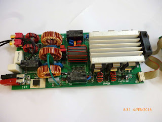
A look under the hood shows a well-planned and efficient use of space as seen in this pre-production prototype shown below. If Collins Radio were to manufacture a 630m transverter for the military, I can't imagine it being any better than this!
 |
| prototype board under test |
"... we carefully match the FETs into three pairs. Each pair is matched to its opposite number but the pairs are chosen so 2 have low gain, 2 have mid gain and 2 have high gain. This improves the IPs and also the harmonics. With matched FETs we are getting the 2nd harmonic at typically -60dB. That's 10dB better than the stringent FCC requirement."
Roger's unit is running at 16 volts and produces 90W output, with his 630m WSPR signal being the one most often heard in North America from down under.
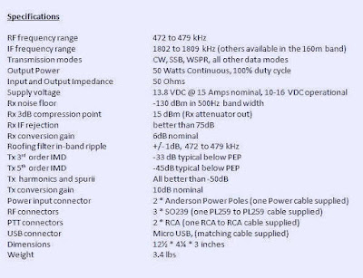
The transverter's multi-colored screen combines with a multi-function menu, allowing a visual on-screen display of numerous parameters such as RF output power, DC supply voltage and current draw, SWR, exciter drive power, heatsink temperature, graphic SWR display and various warning screens.
The transverter requires 3-5 watts of 160m drive from the station transceiver for full output power. Built-in safety circuits prevent overdrive from causing any damage. Similarly, transmitting into a high SWR or with no antenna connected is no cause for concern. Temperature sensors will trigger shutdown should the heatsink rise above 100 degrees C. Software also prevents out-of-band transmission.
This is a microprocessor controlled linear-transverter. This means that operating system software can be readily updated (via the supplied micro USB cable) as new features are implemented. It also means that any mode your transceiver is capable of operating on can be produced on 630m. At present, the most popular modes on the band are WSPR, CW and JT9 but I suspect this order may change once the band is opened up in the U.S.
A shortened eight-page Operator's Manual can be downloaded from the Monitor Sensors web site but units will ship with a more comprehensive 22-page manual. For more information regarding pricing and shipping, please contact Monitor Sensors here. For technical questions, please contact Roger here.


