Posts Tagged ‘630m’
 630m – The Path To VK
 |
| Roger, VK4YB |
I've been exchanging e-mails lately with Roger, VK4YB, in Queensland, Australia.
Roger is located about 30 miles from the ocean and has been the only VK signal that I have been able to hear on 630m WSPR mode. He seems to have the strongest signal out of Australia on 630m with his 90 watts and 120' tree supported wire vertical. John, VE7BDQ, has been heard twice down under with his modest station running at the allowable 5W EIRP limit, being reported in the fall of 2015 and again this spring. As well, John has heard Roger, the only signal from VK that either of us has copied.
I would like to be able to run some schedules with Roger in the fall, when transpacific paths should peak again. With that in mind, construction has begun on a new 630m transverter that will allow me to drive my present FET amplifier at full EIRP. Our schedules will utilize the JT9 weak signal mode, similar to JT65 but designed for the noisier LF and MF bands. It uses about 10% of the bandwidth that a JT65 signal requires, about 15Hz, and gains about 2db more sensitivity. A two-way QSO, under the best conditions, would take four minutes if all went well. A typical exchange of the required information, if initiated at my end, would look something like this:
VK4YB VE7SL
VE7SL VK4YB -20
R -18
RR 73
73 73 (not really needed but indicates RR received)
The path from my end is difficult as I am on the east side of Mayne Island and in Roger's direction, about one mile from a 600' hill directly in line with VK. Any RF heading Roger's way will need to leave here at a fairly high angle, which is likely the case anyway considering the low and short (in terms of wavelength) inverted-L antenna.
The path profile from here to the open Pacific Ocean is shown below, with my end being on the right edge, just behind those two hills. The rest of the obstructions are on Saltspring Island and then Vancouver Island, before hitting open water.
 |
| VE7SL To VK4YB courtesy: Hey What's That Path Profiler |
 |
| W7IUV To VK4YB courtesy: Hey What's That Path Profiler |
 |
| To VK4YB courtesy: Hey What's That Path Profiler |
The path from John, VE7BDQ, already heard in VK, is also easier than from here. Not far from the water, John has a pretty clear shot across Georgia Strait, giving his signal lots of time to gain altitude and clear those pesky Vancouver Island peaks.
 |
| VE7BDQ To VK4YB courtesy: Hey What's That Path Profiler |
 |
| VE7CNF To VK4YB courtesy: Hey What's That Path Profiler |
 |
| VA7MM To VK4YB courtesy: Hey What's That Path Profiler |
 |
| VE7CA To VK4YB courtesy: Hey What's That Path Profiler |
 |
| VK4YB Path To Pacific courtesy: Hey What's That Path Profiler |
As the solar activity slowly abates (but not this week!), propagation on 630m will slowly get better and better ... hopefully along with increased levels of Canadians transmitting on the band, and lots of stations in the USA. It is hoped that our enthusiastic neighbours to the south aren't too far away from getting the band fairly soon. Better get those soldering irons warmed-up so you are all ready to go!
 Is Your Miniwhip Too High?
 |
| The Mini-Whip at University of Twente's (Netherlands) Remote Receiver |
A recent posting to Yahoo's ndblist Group described an interesting experiment by Dirk Claessens regarding the signal-to-noise ratio (SNR) versus height of his PAØRDT active whip. Dirk's tests were posted on Yahoo's Navtex DXing Group where some further interesting discussion seemed to confirm his findings.
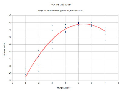
Here is what Dirk discovered, backed-up with his graph data, clearly pointing to the 'ideal height' at his location ... and probably yours as well.
Hi all,
You may recall that to get rid of a source of QRM, my whip is now hanging from a rope-and-pulley system, about 5 .5 mtr from the house, at a height of 7 meter agl.
As the height of the whip can easily be changed, this is an ideal situation to test the behaviour of the whip wrt noise levels, optimal height etc..
I had done this test before some 4 years ago, but not very precise. Time to do it again, and documenting it.
What I also wanted to check, is if there were any noise sources of the own house possibly reaching the whip.
(how far does the "noise bubble" go in function of the height?)
The Perseus was tuned to 549 KHz Deutschlandfunk Nordkirchen, the station closest to 518.
2 markers were set, one to the signal, and a reference marker in a quiet spot nearby on 543 KHz, to get a reading for the noise floor.
The whip was then lowered in "1 meter each minute" steps, readings were taken and written to the marker file.
First the absolute values were plotted.
Note that: blue = noise floor, red = signal, and that the left and right axis scales have identical spans of 19dB, but are shifted, in order to get a compact graph.
We see that for a delta height of 6 meters:
-the noise floor goes up ~8dB, or 8/6 = 1.3 dB/m, almost linearly.
-the signal goes up ~14 dB, or 14/6 = 2.3 dB/m, clearly curved and showing a maximum at ~5..7 m.
The continuous lines are polynomic (2nd degree) regression lines.
The noise on the measurement values seems to increase with decreasing height. Was this caused by my body standing under the whip, and near to the whip for the lowest measurements??
What really matters of course, is the signal over noise value, this is plotted below:
-Within a narrow 1 dB band, the curve shows a clear optimum in the region of 4..7 m agl, a familiar value often given as optimal by Roelof.
-The measurement was performed during the day and thus with ground wave propagation. As the whip is truly omnidirectional, I cannot see a reason why the behaviour would be different at low angle DX signals.
- At 5.5 meter from the house, the whip seems to be outside of the "noise bubble"
and later, following discussion:
I have just checked the noise floor again at 518 (with no signal present)
Perseus set to 125 kS/s, Span/RBW 25/30.5
Shield grounded: -125 dBm
Not grounded: -110 dBm
That's a whopping 15 dB difference!
I have also buried the coax ~20cm deep from the grounding point to where it enters the house.
The ideal height was also that recommended by Roelof, PAØRDT, originally and points out that one of antenna-building's most sacred commandments ... "the higher the better", is not always true!
I have often recommended this simple antenna for those looking for a very effective yet low-footprint receiving antenna for use on the LF and MF bands.
Much more information about Roelof's popular miniwhip may be found in previous blog discussions here.
 CLE 208 Results
This past weekend saw another of the monthly CLE listening challenges.
'CLE's' are 'Co-ordinated Listening Events', and NDB DXers around the world focus their listening time on one small slice of the NDB spectrum.
If you are interested in building a 630m system, doing some listening on the high end of the NDB band is a great way to evaluate your station's receiving performance.
The frequency range covered for CLE 208 was 400-419.9 KHz where a fair number of North American NDBs' can be found. Beacons at this end of the band also tend to propagate better than those at the lower end near 200KHz.
This weekend, typical summertime conditions prevailed, with extremely high levels of thunderstorm / lightning QRN ... propagation itself was not too bad for the middle of summer.
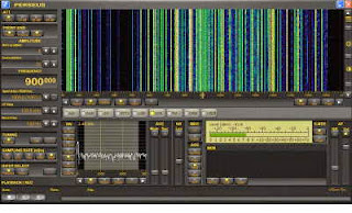
As usual, I set up my Perseus SDR for hourly two-minute captures of the allocated spectrum and spent a few hours going over the files during the day. I have yet to purchase and download the latest version of Perseus software but I understand that there are several improvements over the system I am using ... which is excellent for my present needs.
Here is my weekend CLE log:
02 10:00 400.0 QQ Comox, BC, CAN
02 06:30 400.0 FN Fort Collins, CO, USA
02 10:00 400.0 CKN Crookston, MN, USA
02 10:00 400.0 1L Fort MacKay, AB, CAN
02 08:30 401.0 YPO Peawanuck, ON, CAN
02 08:30 402.0 M3 Kindersley, SK, CAN
02 08:30 402.0 L4 Nipawin, SK, CAN
02 11:00 403.0 AZC Colorado City, AZ, USA
02 08:00 404.0 MOG Montegue, CA, USA
02 09:30 404.0 GCR Cordova, ALS
04 09:00 404.0 FNB Falls City, NE, USA
02 08:00 405.0 9G Sundre, AB, CAN
02 08:00 405.0 2K Camrose, AB, CAN
02 08:30 406.0 YLJ Meadow Lake, SK, CAN
02 10:30 407.0 ZHU St Hubert (Montreal), QC, CAN
03 10:30 407.0 CHD Chandler, AZ, USA
02 10:30 408.0 JDM Colby, KS, USA
02 08:30 408.0 Z7 Claresholm, AB, CAN
02 08:30 408.0 MW Moses Lake, WA, USA
02 08:30 410.0 GDV Glendive, MT, USA
02 10:30 411.0 ILI Iliamna Apt, ALS
02 09:00 413.0 YHD Dryden, ON, CAN
02 04:00 414.0 YZK Harper Ranch, BC, CAN
02 10:00 414.0 LYI Libby, MT, USA
02 10:30 414.0 IME Sitka, ALS
02 09:00 415.0 LO West Yellowstone, MT, USA
03 09:30 415.0 CBC Cayman Brac, CYM
04 08:30 419.0 RYS Detroit, MI, USA
Final details can be found at the NDB List Website and worldwide results, for every participant, will be posted there a few days after the event. If you are a member of the NDB list Group, results will also be e-mailed and posted there.
The very active Yahoo NDB list Group a great place to learn more about the 'Art of NDB DXing' or to meet other listeners in your region. There is a lot of good information available there and new members are always very welcome.
 CW Forever …?
 |
| 24 Hour 'JT' 6m Activity |
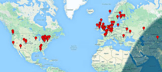
The transverter develops just over 70 watts output when run on 13V and so far, has been able to take all of the nightly punishment I've been able to throw at it with flying colors. Here is a WSPRnet screen shot taken from a typical night of my WSPR beaconing on 630m:
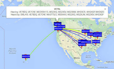 |
| courtesy: KB5NJD's 630m Info |
I was also able to have my first JT-9 mode QSO this week, with Toby, VE7CNF. This mode is the weak-signal WSPR QSO mode, tailored for LF/MF work and allows for calls, signal reports and confirmations (R's) to be exchanged ... the minimum requirements needed to claim a contact. Although additional information can be exchanged, its 13-letter message buffer does not exactly promote ragchew style conversations and some creativity is required to exchange more than the basics.
With many of our newer 'digital-savy' amateurs not necessarily being proficient in CW, I suspect that JT-9 may well evolve to become the go-to weak signal communication mode on 630m, much as it has in Europe. In fact, popularity of this mode in Europe has already spawned a few JT-9 contest weekends on 630m, with high activity levels being reported. I'm really looking forward to a 630m JT-9 QSO party in North America, once the band becomes a reality in the U.S.A.
JT-9 is capable of decoding signals reliably down to -24db SNR and boasts a 50% reliability of decoding at -26db SNR. Audible CW drops out at around -16 to -18db SNR, so communicating with JT-9 is the equivalent of going from 100 watts to around 800 watts ... a significant improvement and very helpful on 630m! Like WSPR, JT-9 will work with non-linear transverters and amplifiers such as the commonly-used and simple to build switching MOSFET Class D/E styles.
There also appears to be a fast-growing use of JT-65A on the 6m band this summer, with numerous 'CW forever' operators finding the mode's ability to dig up to 10db deeper into the noise paying off with surprising results. Some western North American operators have noticed that European JT-65A signal levels indicate that they should be in the CW-copiable range yet no CW activity is heard, for which there seems to be no ready explanation. Perhaps more will be learned this summer as the use of this mode continues to expand.
As one of the 'CW forever' proponents willing to try something different, I also have been listening for and working stations on 6m over the past few days on JT-65A. With the IC-756ProIII throttled back to 25 watts, I've found it fairly easy to make contacts when the band is open but have yet to hear or work anything unusual.
I'd love to hear your own comments on the use of JT-9 or JT-65A, particularly on 630m or on 6m ... maybe you can pass along some tips for those of us that are new to the mode on this band.
I may have to reconsider this 'CW forever' thing!
 630m CW Activity
| John - KB5NJD talks about his favorite topic, 630m |
New experimental licensee, Jim, WI2XJG in Saint George, Utah, recently posted a question on the Lowfer reflector regarding the status of his favorite mode (CW) on the 630m band. The detailed response, provided by John KB5NJD / WG2XIQ, may well be of interest to others as well:
Hi Jim,
Most regular CW QSO's are occurring from about 472.5 to 475 kHz. Note that in Europe 472.5 kHz is a popular frequency. My freq of choice when open is 474.5 because it puts my signals close enough to the WSPR passband that operators there may be alerted to my activity. It seems its become commonplace to use "CW-USB" receive pass bands unlike other low bands that default to "CW-LSB" (At the end of the day it doesn't matter as long as you know since carrier frequencies are what are typically announced).
As mentioned in previous communications much of the CW activity is by sked arranged either via the reflectors like this or the ON4KST chat or even
direct email. While random CW QSO's are not out of the question they are
rare during the summer as activity is decreased in spite of continued
propagation. YMMV. In the past I have mentioned how it might be
beneficial for you to listen to and decode some WSPR to determine the
current state of the band. Regular CW typically requires about -10 dB S/N
in a 500 Hz BW to make a QSO. If you are not receiving stations at -10 dB
or better, you may not hear any CW from that station.
If you live near an area of high activity, of course, this can be a
different result. As I mentioned before I maintain a daily CW sked at
1030z on 474.5 kHz as wx allows but your ability to hear it, particularly
during the summer may be severely compromised. Even those with very good receive antenna systems like NO3M / WG2XJM in Pennsylvania fight the noise this time of year and it can be hit or miss. I think Eric and I had a
total of two QSO's last summer and they were tough. Winter is a different
story and most nights, poor conditions and QSB aside, could yield a CW
ragchew over that same 1300 mile path. In the Winter I get many reports
from stations across North America that are scanning the band and hear the activity. Its not necessarily too different from operating habits on 160m
in that respect.
Activity nights in the Fall and Winter often yield lots of activity as they
have in previous years and those are announced on the reflectors and often
get a mention in QST a few months before.
As for CW activity in Utah, a good start might be Mike, AI8Z / WD2XSH/12
near Denver, Colorado. Mike has a nice signal and you may be able to catch
him on the 600mrg reflector. Also the guys in the Pacific Northwest are
active but I would strongly advise for you to listen to and decode their
WSPRs first to see what your capabilities really are. Your distance from
the PNW is not much different from your distance to me in Texas.
CW speeds will vary with conditions just as other bands. Good signals and
operators can mean fast CW and those same ops under poor conditions may have to slow it down.
JT9 activity is typically on 474.2 kHz USB dial and "carriers" are
typically between 1000 and 1300 Hz up but this varies. JT9 activity has
been low since we have moved into Spring and much of that is due to
abbreviated operating schedules that result from persistent poor weather
conditions. JT9 will require -24 dB to -27 dB S/N minimums typically for
QSO's and may be a good place for you to start, particularly if you arrange
a sked. I don't see much success from a random CQ on JT9 this time of year
unless guys know you are going to be there. Winter is another story and
guys often watch for signals in the waterfall pretty closely. Announcing
your operating intentions is still a good idea so that guys steer RX
antennas your direction.
Best advice I can give right now is to use WSPR to evaluate your station
(RX now and RX/TX when granted) and band conditions at any given time. It will save you a lot of potential frustration later.
Thanks JD and list for the 630-meter bandwidth!
73!
John KB5NJD / WG2XIQ
John and others continue to maintain vigilance on the 630m band nightly and his 630m web pages remain the best source of up-to-date information on band happenings and progress to final acquisition of the band for U.S. amateurs. If you are thinking of getting on 630m now, or later, a visit to John's site will supply you with a ton of motivation!
For Canadians, that already have the 630m band as well as 2200m, I am trying to keep track of Canadian activity here. As well, there has been much information on 630m published on this blog and looking here will bring up all of the 630m related blog posts.
 630m Transverter Project
 I've ordered parts from Digikey for the summer workbench project, a 630m transverter. With the nice 630m WSPR signals received here from Roger (VK4YB) this spring, I think it might be possible for us to work each other using JT9, if the path continues to improve over the next few seasons. On more than one night, Roger's signal was at JT9 QSO levels and had we been on a schedule, a QSO may have happened. Roger's signal was peaking late in his evening, which for me will require making schedules in the wee hours of the morning.
I've been wanting to build another SMD project for some time since making a little SMK-1 40m transceiver several years ago. This was a very inexpensive kit put out by the NorCal QRP Club as a way of introducing SMD construction techniques to beginners. I found working with the 1206 sized parts (basically the largest ones commonly available) to be fairly laborious and would only solder a few parts at a time before setting it aside for the next day. I think my frustration had a lot to do with my positioning and soldering methods and I'm anxious to try doing it with a more refined technique. As I recall, there were 72 SMD components on the board and it took me a couple of weeks to finish it all.
 |
| My SMK-1 40m SMD transceiver |
The parts I have ordered are also 1206 sized but the older I get, the smaller these things seem to look. The transverter will be based partially on the popular G3XBM circuit but will eliminate the PA. Instead, I'll just use a few volts of the transverted squarewave signal and a doubler, so that I can feed the signal directly into my present homebrew amplifier which uses two switching FET modules into a power combiner. Hopefully this system will let me run several of the non-linear digital modes such as WSPR, JT9, JT65 etc.
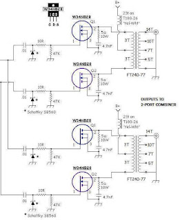 |
| My 630m PA |
As a way of getting back into the SMD-soldering groove, I have ordered and now received, an "SMD Practice Kit" from E-Bay ... a real bargain at $1.78!
 |
| courtesy: Tradeworld2105 |
Although there are many similar practice kits being offered on E-Bay, this was the only one I found that had two IC's to practice with ... all of the others had just one. Since the transverter's doubler circuit has an IC chip, a couple of practice opportunities will be helpful. My only hope is that I don't run out of SMD steam with the practice board before getting down to the actual transverter board.
As soon as the parts arrive from Digikey, I'll start designing the transverter's PCB ... but with all of the usual distractions of summer, as well as trying to maintain vigilance on the magic band once again, my summer project may not progress as quickly as I hope.
All of this assumes that my old eyeballs hold out as well.
 The Joys Of ERP
 Amateurs and and U.S. experimental licence holders operating on the LF and MF bands, are limited in the amount of power they are legally able to run. Unlike the HF bands, where maximum power limits are expressed in either DC power input or PEP output, LF and MF operators are required to observe ERP or EIRP limitations. Canadians operating on 2200m are limited to 1W EIRP and to 5W EIRP on 630m.
 Although this doesn't sound like much, mustering this amount of effective power can be quite a task on either band, especially on 2200m. This is due to the very poor efficiencies encountered when using antennas that are so small in size compared with what would be considered 'normal'. For example, a typical 1/4 wave vertical used on 40m is about 33' high and with a good radial system can achieve efficiencies in the 80% range, while the equivalent antenna for 2200m would be 550m or about 1800' high ... a little large for most suburban backyards!
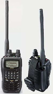
The equivalent of a normal 2m 'rubber-ducky' antenna when built for 2200m would be over 600' tall, while one designed for 630m would be around 170' high! A 2" stub used on your 2m hand-held would be the same as a 56' vertical on 630m. Consequently, most LF / MF backyard antennas will realize efficiencies of less than 1% and likely, quite a bit less.
In order to reach the maximum radiated power levels allowed usually requires several hundreds of watts, especially on 2200m, where near kilowatt levels are needed. These small radiated power levels might seem discouraging but they don't account for radio's great equalizer ... propagation. More than anything else, RF loves to radiate, and at times, what can be achieved on these bands with such low effective radiated powers is stunning
It would seem that Industry Canada did us no favors when they stipulated LF / MF power levels to be measured in EIRP and not the, much easier to calculate, DC power input level ... or perhaps they did. I think that, unlike on HF, imposing EIRP rather than DC input power limits puts everyone on an even playing field. Amateurs with lots of real estate and room for a larger, more efficient LF antenna, will be required to run much less power to reach the allowable EIRP and 'stay legal', compared to someone with a small backyard in the suburbs ... the latter can legally generate the higher level of DC input power required to reach the EIRP limits since their smaller antenna is operating at less efficiency. However, determining EIRP is not as cut and dried as measuring input power.
With some fairly sophisticated (ie. expensive) field strength measuring equipment, not typically found in amateur radio operations, ERP / EIRP can be readily determined. This means that for most amateurs, alternate methods must be used.
Neil, WØYSE in northern Oregon, who runs an experimental 630m station under the call of WG2XSV, has produced an excellent treatise on calculating your station's EIRP level, providing a step-by-step procedure to follow.
In order to determine your ERP / EIRP, you must first determine your antenna's radiation resistance. Two methods of calculating the antenna's radiation resistance for both verticals and top-loaded verticals (inverted L's or T's) are demonstrated, using the physical size of the antenna in relation to the frequency of operation. Once this value is known, the antenna current is measured while transmitting. These two values allow the Total Radiated Power (TRP) to be calculated. The TRP is then multiplied by 3 to yield the EIRP or by 1.82 for ERP. Roughly speaking, 5W EIRP is the equivalent of 3W ERP. Thanks to Neil for this helpful resource.
An alternate method of roughly determining ERP / EIRP values is an interesting new online 'antenna simulator' at the 472kHz.org site. Using known physical sizes along with your ground quality description, the calculator will indicate what total power output is required to produce various levels of ERP and EIRP as well as expected antenna currents, at 472kHz. It's a good starting point if you are either planning a new antenna system or perhaps, repurposing an HF antenna such as an 80m inverted-L or an HF center-fed dipole for use on 630m.
There are also a number of online calculators, such as found here, that will indicate your ERP / EIRP value when you plug in your antenna's 'gain' figure along with your TPO value. Some of the better antenna modelling programs can produce estimates of your antenna 'gain' at 630m and from there it is a simple matter of calculating what power is needed to reach the legal level.
I'm sure there will be a lot more information and discussion about this topic once the LF and MF bands are released in the U.S.A. but in the meantime, calculating your ERP / EIRP levels is not as hard as it might initially seem ... and is likely accurate enough for most agencies overseeing amateur radio activities.

