Posts Tagged ‘amateurradio.com’
 In The Loop! – Repairing a MFJ-1788
Earlier this year I spotted a posting on social media by a member of my club who had brought a MFJ-1788 second hand who was having issues with it not working. I had offered some advice on its repair and glibly offered to take it off his hands should he want to dispose of it. A few months later I got a message asking if I was still interested? I certainly was at the price he wanted.
I collect it at the club meeting a fortnight ago still with a 5ft pole still attached as a bonus! Thankfully it fitted in the car (just).
 |
| Loop as purchased, with pvc tape covering loop |
 | |
| Control Box |
I downloaded the manual and schematic from the MFJ website and I saw there were conspicuous warnings about using an 'isolated' power supply both in the manual and on the back of the controller, with ominous warnings of damage if you didn't. Most shack supplies have the negative/black pin connected to the chassis/ground.
The controller had come to me supplied with a standard fused lead, you know the ones that come to connect your ATU/SWR meter lamp to the shack supply? Mmmm.. my spider sense was tingling!
I pulled out a small double-insulated 12V plug-in supply from my collection (you can spot them as they often have a plastic earth pin) and with nothing else connected powered up the controller. The meter lamp came on and some of the LEDS briefly flickered and heard a few clicks from the internal buzzer then nothing. Pressing buttons did nothing and then I caught the unmistakable scent of burning electronics!
Opening the box up on the bench quickly spotted the source, the regular had well and truly smoked, but since nothing had been connected the short must have been in the controller itself (and it was not the dodgy wires that look like they had been victims to a wayward soldering iron)

Inspecting the rest of the board it was clear that it had been repaired (badly) once before, the two main transistors/FETs (Q1/Q5) used to control the motor clearly showed signs of being replaced (misaligned and with tell-tale scorching from an hot air gun)
a SMD diode had been swapped and one of the 'fine tune' switches had been replaced, its removal had obviously been problematic taking with it some of the through hole copper and adjacent tracks which had been lifted/damaged.


Before opening up the box I had expected to see 'through hole' components and DIL logic ICs not for it to be all surface mounted. Undaunted I went through the parts list and decided to get replacements for all the semiconductor parts not knowing at this stage what I would have to replace. Getting two of each device in some cases five or ten of each due to minimum order quantity, the staggering cost was £8 ($11) including postage!
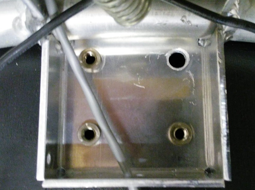
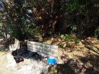
While waiting for the parts to arrive I decided to check out the actual antenna head. I removed the plastic covering and attempted to extract it from the pole..

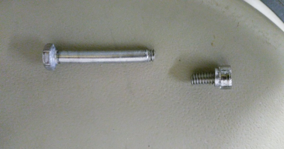
First issue I had was the mounting. One bolt had seized, the nut inserts are held in quite soft aluminium so not surprisingly the insert came out out the mounting when trying to remove it. Using grips to hold the insert the bolt still refused to turn and in the end it sheared off with very little force! Obviously quality fittings these!
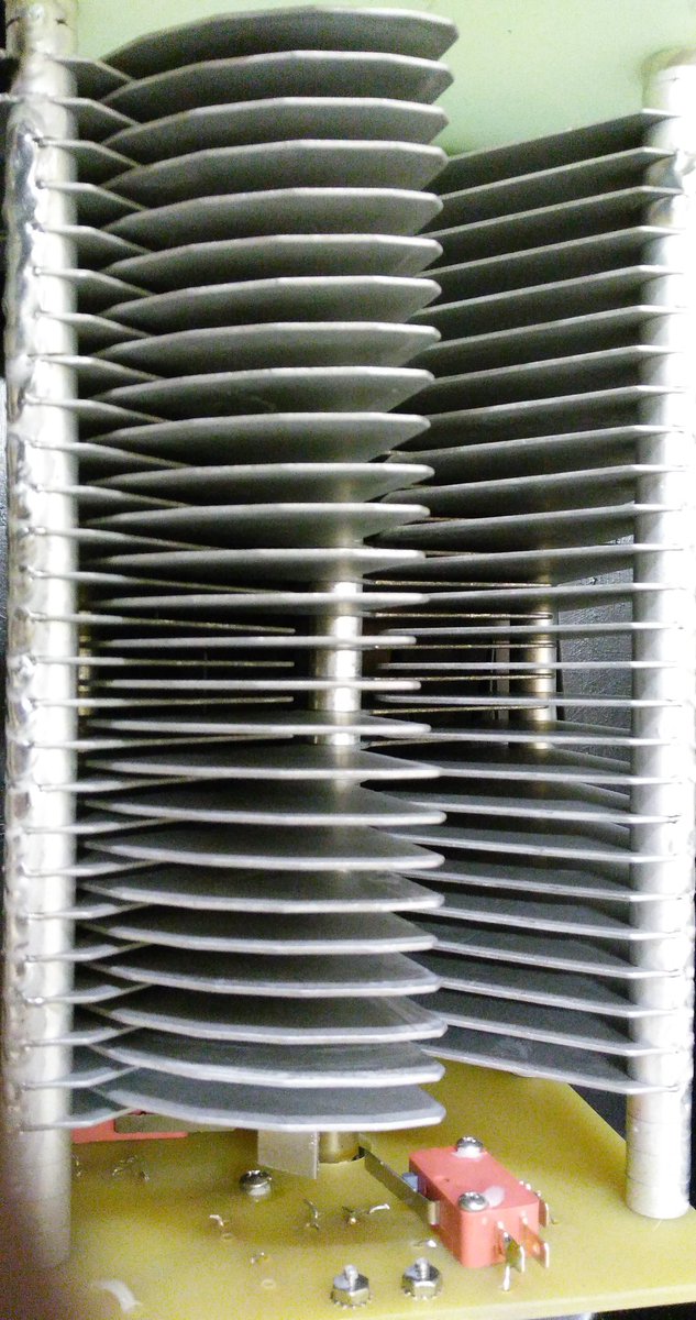
The variable capacitor was suffering a common problem due to poor quality control, the fins had gone out of alignment. Each fin is a separate assembly held on a shaft with a nut to compress them together. It is a simple fix, just realigned and tightened the bolt. The limit switches and motor connection were okay (another common problem) Applying a voltage to the coax connector the motor turned fine, reversing the voltage reversed the direction of turn, the vanes going fully in and fully out before the limit switches activated.
The components arrived prompty and so I got the hot air gun out and set about repairing the board.

I started off replacing the regulator (and the damaged power track) and Q1/Q5 and we had the flickering of life. Pressing the AUTO TUNE button the LED lit and there was 9V across the antenna connector, pressing the other AUTO TUNE button had -9V across. This is why you need an isolated power supply since it reverses the voltage to control direction. The radio doesn't see any of this voltage due to the bias-t arrangement. However if the supply shared the shack ground you would short out the supply, but the current would go via all those delicate electronics! Which is what I think had happened.
It soon became clear that most devices had suffered damage and so I ended up replacing the regulator 78L12, Q1 (SN7002 FET), Q2 (MMBT3906), Q5 (MMBT3906) all the logic ICs CMOS 4001, 4011 and 4066 and the LM324 Quad op-amp chip. I also gave the board a good clean since was covered in grime and flux residue.
Once I was happy the controller was reassembled and connected to my FT-857D on minimum power and the loop antenna propped up against the side of the shack. Success! I was able to successful tune it as per the instructions on 40m and 10m, the two extremes of operation and could here the telltale rise in receive noise as it became resonant.
I have yet to put the loop up in situ for a proper evaluation but have refurbished an old TV rotator to mount it on. I have fitted some nice new quality bolts. The black insulating tape round the loop has been removed, preferring the silver look myself.
 |
| Waiting to be put on the pole |
 |
| Shiny once again |
Assuming it does performs and will find out this weekend, I have paid a total of £65 ($90) (£50 for the initial purchase the rest for replacement parts) which is an absolute bargain as to buy new it is expensive.. very expensive!
One of the main supplier in the UK, have it on sale for £699 ($940) but this includes their engineers inspecting and rebuilding each one before shipping! (Can only be due to poor build quality control and warranty claims) the RRP seems to be around £570 ($770)
It does amaze me how much this units costs new. While the loop construction is generally good, the mounting fittings appear to be poor and the issues with the capacitor and quality control are widely reported.
The components in the controller are not expensive, the switches, meter, box are the usual MFJ fare and the design is quite old (the PCB has copyright 1998 on the silk screen) the auto-tune process requires the radio to be putting RF into a mismatched load for up to a minute and even with low power and SWR protection this isn't good for the radio PA.
Perhaps most surprising is given the risk of damage due to incorrect use is why firstly the loop isn't supplied with a power supply anyway as they only cost a pittance and secondary why their isn't any protection built in? I intend fitting a simple 100mA fuse to offer some protection should a problem occurs.
If the loop performs it may be another project to build a better controller, there are a few designs out there on the internet using Arduino and DDS devices to create auto-tuners. Has that pile of potential projects just grows taller?
73 for now.. and promise to post a bit more regularly
On Learning Humility; a POTA Evening with Bugs in Florida
Monday April 30 I set up at Hobe Sound Nature Preserve, KFF-02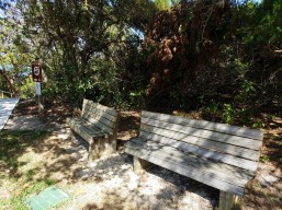 41, to activate on 40 and 20 meters. I waited till late in the day, arriving on site about 5:30pm EDT to set up and get ready for 40m to wake up as the sun goes down. Took my time walking the entire area to scout a good spot. Was previously here two weeks ago in a
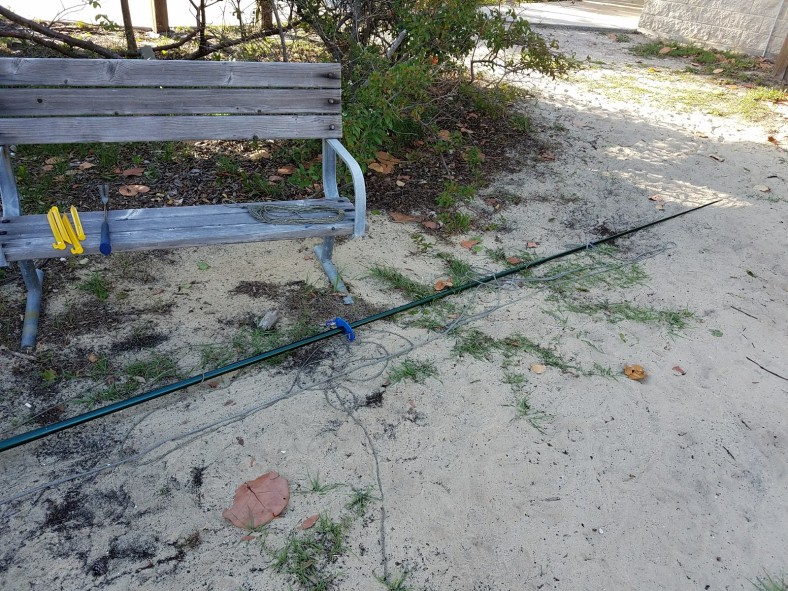
time-pressured situation and hurriedly set up at the first thing I found, a simple park bench. Not that much from which to choose here as this is principally a minimally-developed natural resource area, appealing to fishermen, hikers and nature-lovers, and not as well furnished with picnic areas like a State Park.
Got a eleven or twelve qso’s that day with the Link Dipole arranged up only a dozen feet in the beloved inverted vee style. Not the best operating position, but sufficient.
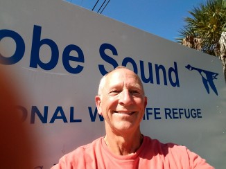
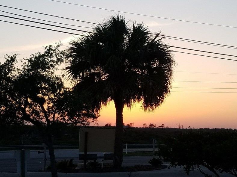
Here I am on the original activation, looking optimistic despite the ominous smoke on the horizon (just a controlled burn, actually).

After an outrageously successful activation of Jonathan Dickinson State Park, only a few miles from here, this past weekend, I just knew I could return to Hobe Sound Preserve and catch many more Q’s to make my 44 needed to earn the coveted WWFF recognition. At JD I got 23 qso’s Saturday but needed more to make the grand total of 44 so went back Sunday and got on the air a little
 past seven on 40m, receiving a total of 49 more in under an hour! Wow, I said; Gosh, I even had a little pileup going a few minutes at a time. “Oh Baby, That’s a What I Like,” (with a Hatlo Hat Tip to the Big Bopper). Couldn’t wait to do that again at Hobe Sound today.
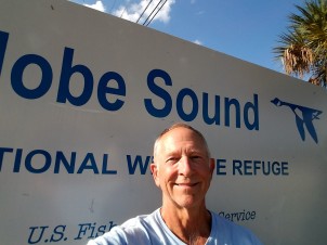
Confidently, I left the house 5pm to head to the site. Sorry I don’t have a picture of me confidently driving my car but just look how confident I’m still looking upon arrival; who wouldn’t want to work a ham like this one?
Took my time to walk most of the trails to scout the best location to set up and found this tranquil spot: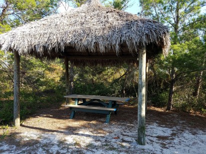
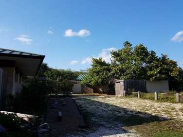
No cooperating trees in vicinity, so let’s set up a tower.s Below’s the view from the idyllic picnic table and thatched roof. The open area is to the North-NorthWest, ideal aiming direction for Southeast coast of Florida. Same orientation as yesterday – good omens.
I’ve learned how to erect a tower alone; step one is to lay out the antenna (EndFedz in this case) to judge where to place the tower and its guy lines. Lay the tower down, tie on the guy lines and provisionally place your tent stakes. Remember to attach the antenna and attach your coax to said antenna (this is the voice of experience speaking) before pushing up the tower. This is the dicey part, when having an assistant would be helpful, but in the spirit of self reliance, you can do this if you’ve guessed well where to place the tent stakes. Something I’ve started to say to the Curious, especially when the Curious is a Park Ranger, when they ask what you’re doing, say “I’m setting up a radio station in a simulated emergency situation.” They will eat this up.
After some fumbling, your tower will finally look like this:

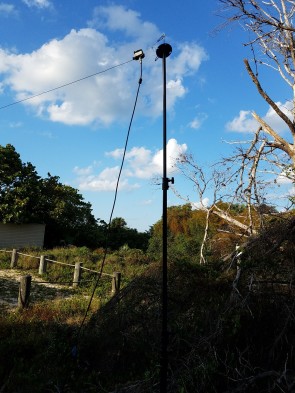
This tower tip is at 22-23 feet; yesterday, same time, same antenna, and same band, I was up 35′ thanks to a handy tree. But still, this looked really good so I expected similar if not better results, qso-wise. Here’s the low end of the EndFedz on a photographer’s lighting tripod, up ten feet and guyed.
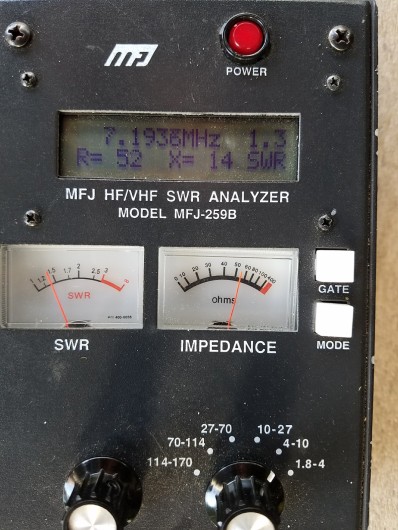
Bodacious good SWR as you can see in image below. All’s well, it seems.
Eager and self-assured, about 6:30 I begin calling CQ, ready for the inevitable pileups. Quickly I stumbled into a net and was invited to check in, so I did. Not POTA, but
a start. A next contact happened 2-3 minutes later. These always start slow, right? Twenty-seven minutes pass, my confidence dwindling, before getting another contact, AA5UZ, whom I worked yesterday. I’m going, “what’s wrong?” This same setup yesterday was causing pileups; I could hardly write down the call signs fast enough. I fiddled with the antenna, getting it higher, but no improvement in qso rate.
So what is it? Is it Monday versus Sunday, are the bands that different one day to the next, is it that I the antenna location is that much different to limit results? I kept at it, watching the sun go down and aware I failed to pack a table lamp or a decent flashlight but wanting the darkness to come and boost results. Had a few small stretch when I got 4-5 contacts in quick succession, and heard others trying me that I just could make out, but nothing like yesterday.
I dunno; packed up at 8:17 (end of civil twilight), and it was pretty dark when I finally departed, rather deflated. This was a lot of work for eleven qso’s, and I’m still only half way to the magic forty four. From the time I left the house to when I returned, it was over four hours invested. As an experiment, I will return to the happy spot at JD State Park where I got the 49 in an hour, and try again there to see if similar results occur at the same time, same band, same antenna setup. Stay tuned!
But for now, it’s time for ice cream; that usually makes me feel better. Thanks for listening; you’re in the log. De k4wk, Wayne, http://www.hamdom.com
Vanity Calls – More practical than vain
When I was a Grasshopper Ham, and somehow stumbled my way through the 20 wpm code requirement then in effect to become an Extra Class, I wanted something more than KT4QK. I wanted my initials (vainly, but in vain), because K4WR or W4WR were not available when the vanity calls came out in the nineties. Living in the South, I wanted a “four” call so I did limit myself that way.
In truth, it seemed that one of those calls might be available as it had expired and not been renewed by an older ham in Alabama. It wasn’t really up for grabs yet as less than two years had passed since expiration, so I surmised he had passed on to the land of ham radio nirvana (you know, then one where there’s no qrm or qrn and the sun spots are always hot and the DX always hears you), but I felt funny trying to reach his widow or family to see if he’d died so I didn’t do it. Instead, I settled on K4WK (Wayne K Robertson is my name) and I love it; dandy for CW.
WA4YNE was available at the time and momentarily tempted me as something clever, but as one who operates CW more than Phone, felt it would be kind of messy, a sort of morse code tongue-twister.
WA4YNE has now been claimed by a ham named Thomas but his middle initial is W so maybe that’s for Wayne, and W4WR is now owned by someone who’s initials match, so I hope everyone’s happy and radioactive.
This is Wayne, k4wk, http://www.hamdom.com. Thanks for listening; you’re in the log.
#POTA Activation of JD Mac Arthur SP in South Florida
This, my second POTA activation, was a much bigger su ccess (39 qso’s in an hour) than the first (a mere dozen), despite #2 being on a weekday afternoon vs. Sunday for #1. I attribute this to my savvy scheduling to avoid ARRL’s DX Contest and at the same time, ARRL’s respectful consideration for a Big Gun like me in not trying to compete! As the Borg said, “Resistance is Futile.”
The other big factor was getting a few hams to spot me on the clusters. I was quite surprised, and thrilled actually, to be the subject of a pileup for a few minutes. Imagine, lil’ ol’ me, being sought after; I hardly knew how to handle the fame!
Things started kinda slow, my first contact being a ham about two miles away; I’m thinking, oh boy, this’ll be a long afternoon. Will I ever get the requisite ten qso’s to count a POTA activation? I tried to spot myself but on Dxsummit.fi it is so awkward to do on your smartphone. With ten thumbs like me, mistakes are made. I did ask several hams to spot me and soon a few did, and then I was in demand, even at 4pm on a Tuesday afternoon. I never knew there were so many retired or unemployed hams sitting around bored during the day. From South Florida I worked hams in NY, CT, MI, PA, MN, AZ, CA, England and Spain!
I used my link dipole antenna up approx 24′ at the apex, set for 20m. By closing a pair of links, it can be reset for 30 or 40 meters. I built this antenna a while back, and tuned and trimmed it carefully for each of these bands, so no tuner necessary. I’ve tried a PAR EndFedz and a homebrew Buddipole for HF and this is the best for me, thus far.


From left to right: the dipole (made of speaker wire) rolled up on custom deluxe wire winder; middle, the handsomely crafted center SO; and right, the links for 30m, left open so antenna resonates at the shorter 20m cut. Note “stress relief” at the SO and use of safety pins to carry the tension of the dipole when hoisted. Below is pic of my antenna launching tool; it was too heavy at first so I drank half the contents. Also below is a pic of my tie down line, fluorescent builder’s twine. I’ve decided to be stealthier in the future and will change that out for something that’ll blend better.


I want to be stealthier so I don’t draw attention to my station and my suspicious behaviors. Even though I have a right to be there at a picnic table not all Park Rangers got the memo and some may think they should run me off. Last week a Ranger did stop by and I thought “well, here we go,” but actually he just wanted to chat; his Dad had been a ham, so I tried to recruit him. I had another visitor, too; note to self, don’t operate so close to garbage cans!


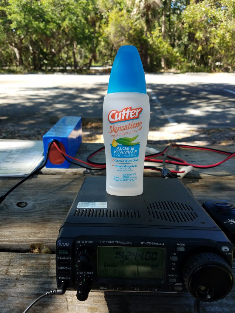
And finally, a note to the wise for operating out of doors in Florida; bring your bottle!
This is Wayne, k4wk, http://www.hamdom.com. Thanks for listening; you’re in the log.
QST Article – “Live Trees Affect Antenna Performance” – implications for #POTA #SOTA
In February 2018’s QST was a very interesting and scholarly article, the cover story actually, on the effects of live trees on the performance of both vertical and horizontal antennas. Things to ponder:
- Living wood (trees, as opposed to dry dead wood such as boards) absorbs EMF from vertically polarized antennas.
- Living wood resembles human tissue in terms of dielectric properties, so wearing your HT on your belt will greatly reduce your effective antenna power. Presumably, unless you’re a real fathead like me, talking into HT held at your face should not be too bad.
- A single vertical tree has next to no effect on horizontal antennas, such as dipoles.
- A forest, containing lots of vertical trees, is even worse than a single tree like in your backyard, so for us backpackers and hikers, we need to find a clearing when trying to use our HT’s in the woods.
- Worse, a forest will affect both vertical and horizontal antennas so when we’re operating in the field, for POTA or SOTA for example, we should look for a Goldilocks spot with enough trees to launch the, say, dipole, but not too many. Better in Winter after leaves fall, though.
This is Wayne, k4wk, http://www.hamdom.com. Thanks for listening; you’re in the log.
My #POTA Pickle, or How I Learned to Stop Worrying and Love the ARRL #DX Contest
Sunday March 4th was a beautiful and slightly cool (mid-seventies) day in Jupiter, Florida and was the day I selected for my first #POTA activation (parksontheair.com). I picked the 11,000 acre Jonathan Dickinson State Park, KFF-1887, just six m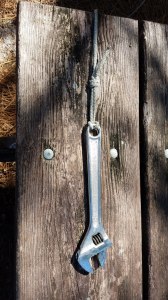 iles from my Florida QTH. I scouted out locations a few days earlier and chose the picnic area near the river, with cooperating pine trees with handy limbs. Using my unique antenna launch tool (see pic) on only the second try I hit my target limb and hoisted the “high” end of an EndFedz antenna cut for 20 meters. My battery was charged, I had my sandwich, I even had a cushion for the hard picnic table bench seat. Right on time I was ready to spot myself, all settled and happy. Do you hear a “but” coming?
This was 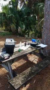 also the weekend ARRL chose, without checking with me, for their hugely popular annual DX Contest. There were a few thousand hams on 20m, most, it seemed, with a kilowatt and a pretty good beam competing with me barefoot with a dipole up all of fifteen feet. I spotted myself on DXSummit.fi but apparently nobody cared. I raised my friend Rick on the local repeater and got him to listen for me at 14.244 a few miles away and we could barely hear one another on ground wave. We were in a wall of sound (and I was learning the value of a filter for sideband.)
So there’s my POTA Pickle; I’m in the right place and all set to operate POTA but cannot compete with a thousand big gun stations. Well golly, let’s join in on the fun then.
First I took down the End Fedz that just doesn’t work that well for me and put up my link dipole made from lamp cord and began to hunt and pounce. Worked a dozen international stations in an hour and called it, after all, a good non-POTA day.
This is Wayne, K4WK, http://www.hamdom.com. Thanks for listening; you’re in the log.
Review – BTech AMP-25 series for Analog & DMR
The AMP-25 series VHF / UHF Amplifiers

The recently announced BTech Digital and Analog amplifier series puts a whole new spin on mobile operation. It performs more like a mobile than it does a power amp. The D series are true TDMA Tier2 DMR amplifiers.
Note: This review was done using an Anytone D868UV on both DMR and analog.
In the Box
Included with the 40W Mobile Amp are:
– Mounting Bracket
– 3′ Interface Control Cable (Kenwood K1 connectors)
– 3′ RF connect cable (SMA-M to SMA-F)
– Microphone and Hanger
– All necessary mounting hardware
– User Guide
General Description
– UHF or VHF Power Amplifier
– 2-6W > 20-40W Output
Modes of operation include:
| V25 U25 | V25D U25D |
| Analog (FM) C4FM (Fusion) P25 (Phase 1) NXDN IDAS dPMR MPT1327 | > DMR Tier II (TDMA) > P25 (Phase 2) Analog (FM) C4FM (Fusion) P25 (Phase 1) NXDN IDAS dPMR MPT1327 |
A Different type of Mobile Amplifier
I found these to be much more than a typical power amplifier. Although they can function as a simple ‘In and Out’ power amp, this is about as close to a full mobile as you can get. Although the driving  force was my DMR handheld sitting in my cup holder, the transmit audio was that of the included hand microphone and the receiver audio out was coming through the built in speaker driven by a four watt audio amplifier.
Transmit Power
I tested the power on two different models. The VHF V25 (non TDMA) and the U25D for UHF DMR. The power was tested using the analog side of both into a calibrated Bird Termaline wattmeter. The maximum current drain from my 13.6V 30A power supply was just under 6A. This is low enough for the amp to be powered by the 10A accessory jack in your vehicle.

Enclosure
The basic frame measures 4.6″W x 1.3″H x 5.5″D (excluding the SO-239) and weighs in at 26oz. I was curious to see the internal layout of the amp and to no surprise, there was a 5/8″ finned heat sink spanning the entire length and width of the case along with air vent along the back of the enclosure.
Operating Modes
These are single band amplifiers.
V25(D) = VHF 136-174MHz
U25(D) = UHF 400-480MHz.
Note: The V25D and U25D were designed to include DMR Tier II (TDMA) and P25 Phase 2 along with all other modes. Their operation varies slightly.
V25 / U25
To operate VHF through the UHF (U25) amplifier, or UHF through the VHF (V25) amplifier, simply power off the amplifier. This will allow you to run straight through directly to the antenna without power amplification on that band.
V25D / U25D
These amplifiers will only operate within their specified VHF or UHF range. This is due to the circuit switching design of DMR Tier II and P25 Phase 2.
Hook Up
The simplest configuration is using the included RF cable to attach the radio to the amp. You could add a Spkr/Micr to the handheld, but you would still be bypassing some of the best features.
I use the two included cables. The 3′ RF cable to attach the radio to the amp, and the control cable. This allows me to use the full size hand microphone as well as connecting the four watt audio amp powering the speaker. The power included power cable is compatible with handhelds using the standard two pin Kenwood style connector, such as an MD380, D868, GD77, UV5R, F8HP, UV82, etc.

I use an Anytone D868 on DMR as well as analog with the hookup diagrammed below. Depending on your radios antenna jack, you may need to pickup an SMA-M to SMA-M adapter.
Convenience
All channel selection and volume adjustments are done using the handheld. No duplicate programming or code plugs are necessary. Whatever is in my handheld is what I operate in the mobile
Operating my handheld in the low power position, I still get 22W out on UHF and my handheld’s battery life remains excellent, but high power gives me a solid 39W.
Conclusion
I was glad to see someone finally develop what is a full featured mobile amplifier capable of DMR as well as all other modes including C4FM and D-Star that is small enough to mount in the car, boat, and on top of your computer. This amplifier is Part 90 certified and definitely worth considering.
Available from Amazon: V25 V25D U25 U25D
and ![]()
VHF /UHF
Digital / Analog
Mobile Power Amplifiers
![]()
![]()


