Posts Tagged ‘amateurradio.com’
 Got a proper radio, well it’s on order!
I have ordered my first proper 'rig' It is a Yaesu FT-857D a nice small, portable/mobile unit that will give me access to the HF and 6m/2m/70cm bands in all-modes. It has took a while since I first identified it as potential purchase but thanks to some generous Christmas presents I now have the sufficient funds and following several recommendations have decided to take the plunge and ordered it from Waters and Stanton
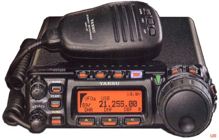 |
| She is a beauty! |
I have a decent 7A PSU, purchased last year which I am sure would have sufficed for 10W maximum operation however I decided to also purchase a MAAS SPS-30-II 30A(35A peak) PSU. It was a good price from Radiozing and offers plenty of power for anything I am likely to run in the foreseeable future, and from the pictures and reviews seems to be built like the proverbial brick out-house. As well as the main connectors on the back it has spring clip terminals on the front as well as a cigar lighter type connector. Dual meters showing V/A and can be used in variable mode from 9-15V or fixed at 13.8V
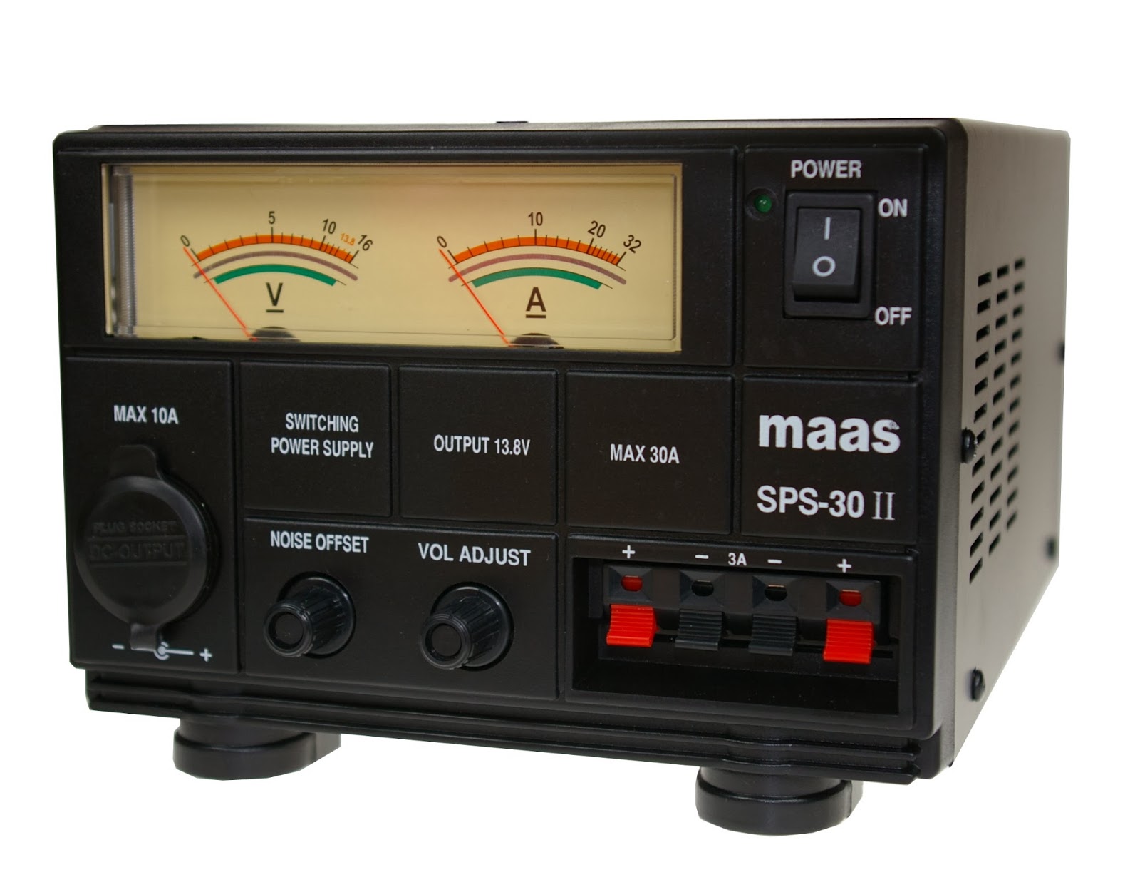 |
| This is the beast! |
Delivery should be later this week and I suspect I have a large learning curve ahead of me as I hit the airwaves! If you should hear me please be gentle..
FUNCube Decode Issues
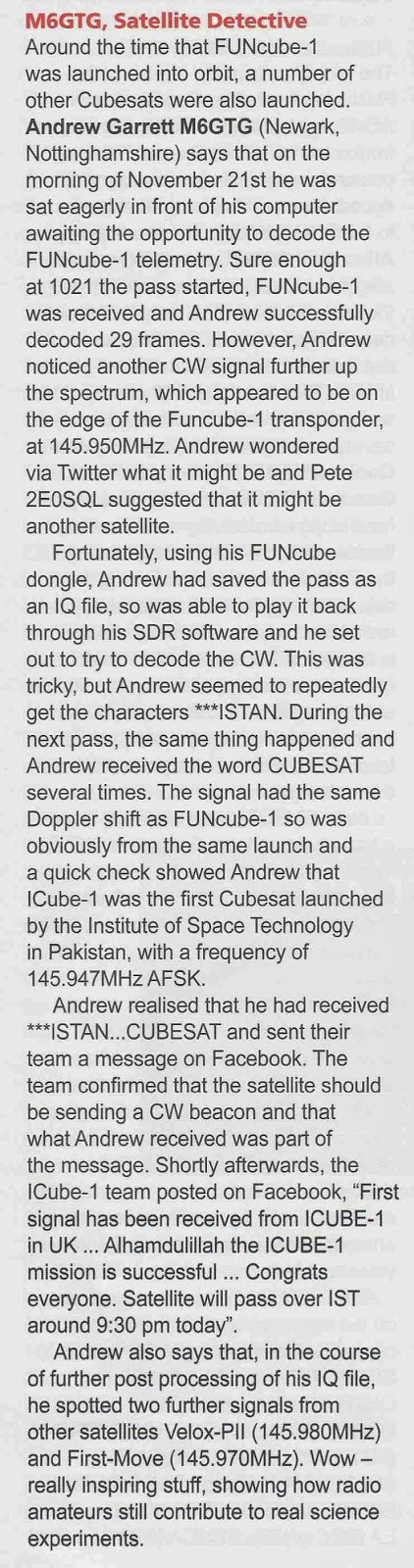
I also had a small write up in Tim Kirby's (G4VXE) VHF/UHF section of the February issue of Practical Wireless about my I-Cube1 reception which I have mentioned on here before.
I haven't progressed very far with my Arduino projects. There has been a set back in the plans to build and use an Ultimate3 QRSS kit. I had incorrectly assumed as it was a kit being sold commercially that it would satisfy my foundation conditions. However I have been advised that Foundation license holders may use radio equipment constructed using commercially available kits which satisfy IR 2028 which is all a bit vague and woolly, but I don't believe this particular kit does.
There is a simple solution, I will just have to take my intermediate assessment and exam at the first opportunity!
I have been doing a little WSPR spotting, getting some nice spots.

Over the Christmas/New Year period I have neglected the FUNCube-1(A073) satellite and was slipping down the telemetry upload rankings, sad I know!
Now I have got back the upstairs 'shack' I set up my original FUNCube Dongle on the laptop running the dashboard application continually to capture/decode the telemetry using the loft mounted discone. I took the opportunity to upgrade to the latest version 8.14 of the dashboard software, however something was amiss when checking the statistics I was only adding the odd frame here and there, sometimes not making a single decode during the high power daylight passes.
I switched back over to the newer FUNCube Dongle PRO+ running my main PC, which I had also updated to the version 8.14 dashboard and saw the same behaviour, rather than getting daylight decodes of 30+ frames I was just getting the odd 1 or 2.
My first thought it was an antenna or interference issue, but checking the SDR waterfall the signal is still very strong with little QRM. Suspecting a software issue introduced by the update I checked the FUNCube forum and found a thread which appeared to confirm my suspicions.
I have a number of discussions on twitter with various people including David Johnson (G4DPZ) an AMSAT-UK Committee Member and one of the developers of the FUNcube ground segment. David kindly performed an analysis of one of the passes yesterday where I managed just 2 frames, and from the results it does appear to be an issue at this end, rather than issue with the spacecraft.
I have uninstalled v8.14 and put back on an earlier version of the dashboard (v8.09) and thanks to a windows update last night have also performed a full reboot!
There was a good pass this morning at 62 degrees maximum elevation (to the east), followed by a lower pass at 22 degrees elevation (to the west so not so good) and it seems things have improved managing 68 and 17 frames respectively. So could this be an issue with the latest dashboard?
If anyone has suffered similar performance fall-off, or indeed not suffered any issues then please add some feedback to the FUNCube forum.
My copy of Radcom arrived but didn't have much time to read it..
 |
| The culprit! ;-) |
Another Day Another Arduino Project
As I mentioned in passing yesterday I have a number of Arduino based projects buzzing around in my head. One of them is to produce a satellite antenna pointer/indicator.
I have used an Android AR tracking solution before (flaky at best) and can see the relevant information in Orbitron or SatPC32 to know where to point the antenna but it is difficult to see a PC screen when stuck out in the middle of the lawn!
My idea is this, I will make a large tripod to which I can attach appropriate antenna as I need, then during the satellite pass it has indicators to show where to point the antenna manually.
I envisage the azimuth indicator to be a large horizontal circle with 36 LEDs positioned at 10 degree intervals, the elevation will be a quarter circle with 20 LEDs positioned at 5 degree intervals. Then during the pass the appropriate LEDs will light and assuming I keep the antenna aligned to these I should in theory get the best signal... Crazy??
Yes I know I could make or buy an azimuth/elevation rotator, eBay is full of low speed high torque geared DC motors with auto-stop/hold and numerous software solutions exist to drive them but this would require a bit more engineering and isn't something I can easily fabricate at the moment. My contraption would be much more rustic being made of rough cut timber!
Bright LEDs are ridiculously cheap and controlling this number from the Arduino will require the use of multiplexer drivers. The popular ones are the MAX 7219/7221
I won't go into the details of exactly what multiplexing is, other than to say that each display element (LED) is driven one at a time but by switching the electronics at high speed combined with the persistence of vision make the viewer believe the entire display is continuously active.
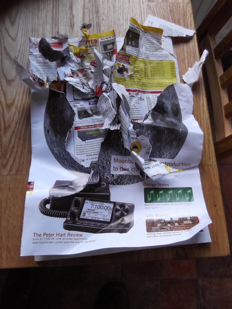
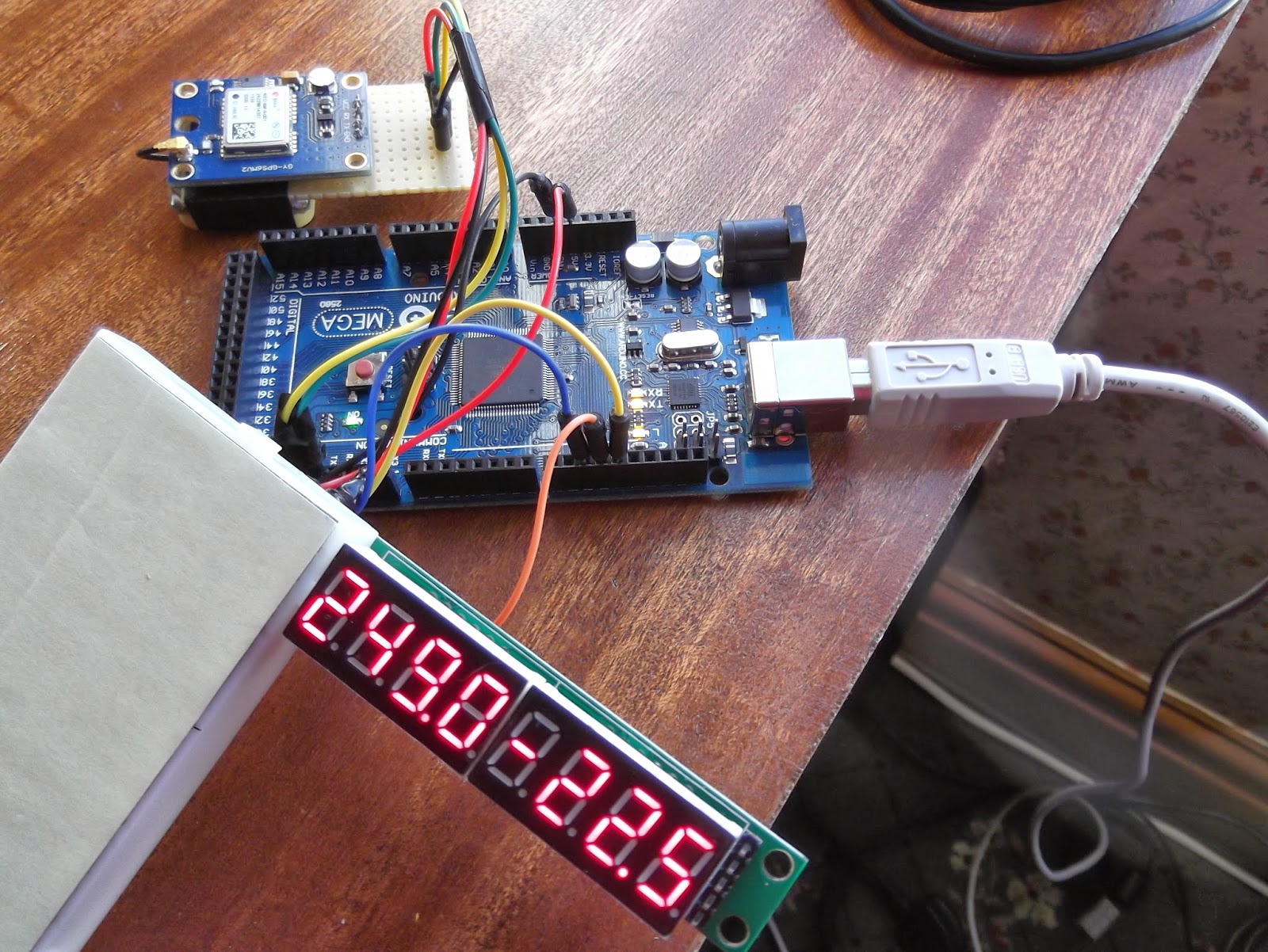
This technique can be used for individual LEDs, an LED grid matrix, or for 7 segment displays. Last night I successfully got a MAX7219 based 8-Digit 7-Segment LED module working.
The next stage was to investigate how an Arduino could calculate the appropriate azimuth and elevation data. Thankfully a library already exists qrpTracker (code is here), within this library is a port of the Plan-13 algorithm first written in Basic by James Miller G3RUH in 1990, subsequently ported to C by Edson Pereira, N1VTN and further updated by Howard Long, G6LVB.
Plan-13 processes keplerian elements, time and (optionally) observer location, and uplink downlink frequencies; it outputs satellite latitude and longitude, azimuth and elevation, and Doppler shifted frequencies. At the standard 16 MHz Arduino clock speed, this code can complete these calculations in approximately 30 ms. This code is reported to be highly accurate, if provided with proper data.
The important data are the observer location (longitude/latitude) and the current time. Step forward my well used GPS module which once lock is achieved can supply that data.
The next is get the appropriate up to date Keplerian twin element sets (TLE) and extract the appropriate information from it and pass that data to the Plan-13 functions.
The standard TLE follows the following format
You need to extract the Epoch Year/Day (including partial data), Inclination, Right Ascension, Eccentricity, Perigee, Mean anomaly and Mean Motion for a calculation (drag/orientation aren't critical) For the moment I have just extracted this manually from the latest TLE and entered it directly into the program.
After just an hour or so of research and programming I have the LED displaying the current azimuth and elevation of the FUNCube-1 satellite (AO73) based on the current position and time derived from the GPS!
The first four digits is the azimuth, the second four the elevation.
Arduino, WSPR and AD9850 DDS experiments
Christmas is thankfully behind us so I can get back to what I enjoy doing once I have reorganised my workshop.
As you know I am currently developing a potential High Altitude Balloon (HAB) project and have been experimenting with the Arduino microprocessor platform and have constructed a basic prototype.
With the arrival of the GPS module(s) I have had it successfully working and even took it out for a test walk in the local area, receiving the data and uploading it to the UKHAS habitat system.
NERD-1 and Boris have just been for a walk, first time NERD-1 has had proper GPS and running on batteries. #hab pic.twitter.com/RaKsf1rQhr
— Andrew Garratt M6GTG (@nerdsville) November 23, 2013 This project has revitalised my interest in 'hobby electronics' and I have ideas for a number of other Arduino based projects and have been splashing out on components from eBay. Just before Christmas I purchased an Arduino Mega board, this has more I/O pins than the current Uno and specifically some extra hardware serial ports.
Do any internet search for Arduino based amateur radio projects and it will results in numerous mentions of projects using ultra cheap DDS modules based on the Analog Devices AD9850/AD9851 chipsets.
DDS means Direct digital synthesiser and is a type of frequency generation which can be used for creating arbitrary waveforms from a single, fixed-frequency reference clock. Read the Wikipedia page for more details.
In a nutshell the AD9850 is a chip that under microprocessor control can produce a sinusoidal wave from about 1hz to 40mhz. In other words it is an accurate microprocessor controlled VFO (Variable Frequency Oscillator) or signal generator.
VFOs are the main building blocks of radio receivers and transmitters, so not surprisingly a lot of projects have utilised these modules, rather than the traditional means. Intrigued I ordered a couple of these modules for the pricey sum of £3.50 each!
Using information on George Smart's (M1GEO) website and Simon Kennedy's (G0FCU) blog I quickly had a simple WSPR beacon running!
Experimenting with Arduino and AD9850 DDS and GPS unit.. pic.twitter.com/rxDHQQ1aFd
— Andrew Garratt M6GTG (@nerdsville) December 29, 2013 The Arduino uses the GPS module borrowed from NERD-1 for accurate time and then controls the output of the AD9850 DDS to generate the WSPR signal.Before anyone panics I know at the moment I only hold a Foundation Amateur Licence so the construction of homebrew transmitters isn't allowed. This 'beacon' has no power amplifier and the antenna consisted of an inch or so of wire on the DDS output. I was able to verify the operation using my SDR receiver in the same room.
Construction of commercial kits is allowed under my licence so I have ordered a Ultimate3 QRSS kit from Hans Summers for the pricely sum of £17.50! This uses the same DDS module and same microcontroller as the Arduino.
In the meantime there is also more information and ideas on Eugenr Marcus' (W3PM) webpage about the use of these DDS modules, including making frequency reference sources and calibration using the GPS module.
My new year resolution is to get my Intermediate Licence as soon as possible.. but it has been great to get down to some proper experimenting...
Cannot beat a picture of an oscilloscope to look techy.. my DDS experiments continue... pic.twitter.com/T9OLHOdTLW
— Andrew Garratt M6GTG (@nerdsville) January 1, 2014 Mentioned in Practical Wireless! and some Christmas stress
This has meant I have had to tackle some long put off home renovation projects. The first was to redecorate the bathroom and what should have been a simple paint job has snowballed into a major project and has sapped a lot of free time. Thankfully it is now all but done.
The second was to turn the third bedroom back into an actual bedroom rather than the study/computer room/indoor radio shack it had become. Again this involved more work than planned including dismantling and remodelling of a home-made desk and the removal of piles of collected radio/computer junk and books.
The upshot of all this work and de-cluttering is my outside workshop has turned into a bomb site! Most of the junk has been dumped in it and it is very untidy with tools scattered everywhere. I also had a minor catastrophe when trying to retreive a workmate when my beloved 2Meter YAGI, fell off its perch breaking off the reflector and a director! Thankfully Justin at InnovAntennas was able to sort me out some replacement boom insulators
With all this upheaval, combined with work pressures I have been unable to really do any radio or electronics for most of this month. Do I sound like the Grinch?

Despite this I have been able to capture the odd FUNCube-1(AO73) pass and have nearly reached 1000 telemetry packets.
It came as a pleasant surprise was finding out I was mentioned in the January issue of Practical Wireless magazine. Tim Kirby (G4VXE) reported on my ISS SSTV capture and APRS experiments. Tim the magazines VHF/UHF editor has his own blog and is someone I converse with on twitter (@G4VXE)
I realised I didn't blog my SSTV capture back in October, but did post it on twitter feed (@nerdsville)
Not sure what it is, but this SSTV image just received from the ISS with completely the wrong antenna! pic.twitter.com/5uka2aHfic
— Andrew Garratt M6GTG (@nerdsville) October 28, 2013 Here is a scan of my mention and the picture.. I can forgive Tim misspelling my name, it happens a lot! It also seems I might get mentioned in the February issue to following my ICube-1 reception report.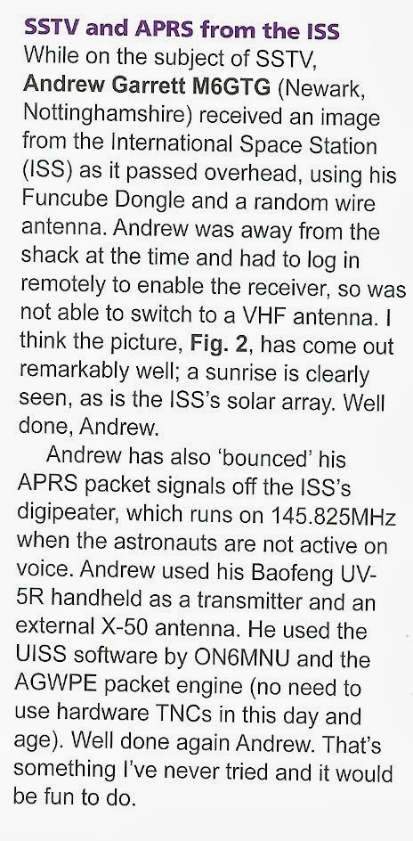 |
| From Practical Wireless - January 2014 Issue |
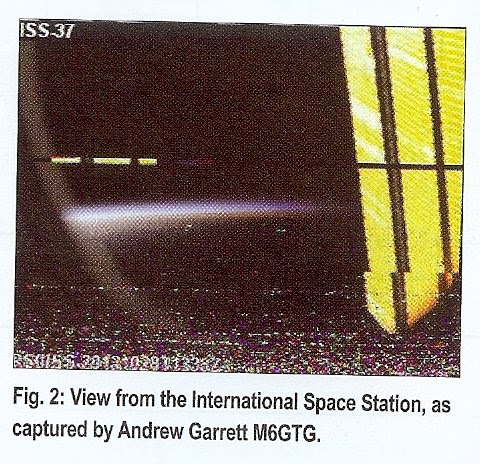 |
| From Practical Wireless - January 2014 Issue |
Where to find the $20 Software Defined Radio?
A while back I wrote a blog post about the availability of $20 software defined VHF/UHF radios in the form of re-purposed USB digital television dongles.
Now-days, with the improvements in software and documentation, the hardest part is finding the right dongle. What you order from EBay, and what you receive, can be two different things and only some of the dongles are suitable for use as VHF/UHF software defined radios.
So, I was pleased to see that at least one hobbyist electronics supplier has sought out and supplies a suitable device for SDR at a fair price :

Adafruit has available the USB dongle and “antenna” suitable for experimentation for $22.50, not far from the EBay (direct from China) price.
Click here to go directly to the product page: Software Defined Radio Receiver USB Stick – RTL2832 w/R820T
No, I didn’t receive a free evaluation unit and I don’t work for Adafruit … I’m just glad to see these useful devices available from a local company with an increased chance of you “Getting what you paid for.”
Adafruit also helpfully stock the adapter cables to convert the less common MCX antenna connector into the much more common BNC connector: MCX Jack to BNC RF Cable Adapter
I’m famous! and ICube-1, MOVE and Velox-PII telemetry decodes
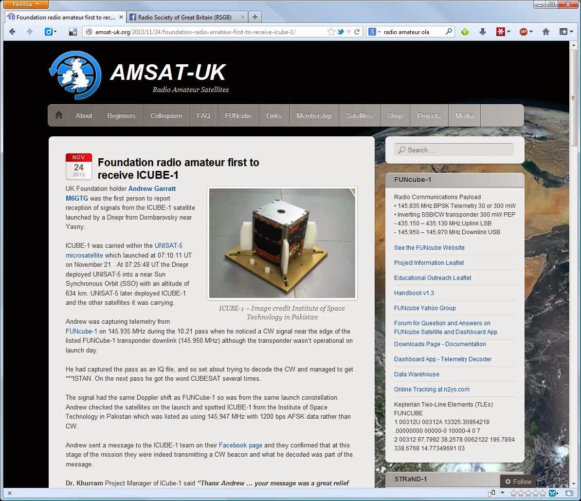 |
| Screenshot of the Amsat-UK webpage |
I had the IQ file from SDR# so could process it as much as I needed and have used a couple of Morse/CW decoder tools before, but find the free ones often struggle with the faint Doppler shifting CW, just a little too much noise and not enough signal.
Audible decoding isn't an option (yet) but I can visually decode, but the signal going up the waterfall shows the dots and dashes but is too quick for me, and ideally I would like it horizontal rather than vertically.
Then I remembered I had installed Spectravue a few years ago, Spectravue is a powerful spectral analysis/receiver program primarily for use with SDR devices, it was the program used to calibrate my first FUNCube Dongle.
Spectravue is able to take the IQ file and play it back at varying speeds, it can demodulate signals and importantly allows pausing of the playback and easy access to the section of interest, something SDR# is sadly lacking, also it allows a horizontal waterfall display and the ability to save images.
I set about processing and decoding and as you can see from the screenshots below, I managed to identify most of the message (the letters have been added later) The FUNcube-1 telemetry signal can be seen at the top of the images, along with some QRM.
 |
| Partial decode of ICube-1 CW beacon |
 |
| Partial decode of ICube-1 CW beacon |
During the process I also spotted two further signals from Velox-PII (145.980 MHz) and the First-Move Cubesat (145.970 MHz) - both of these were recorded in the first decent pass over the UK after deployment (10:21 on 21 November 2013) the incorrect time shown on the bottom of the screen shots comes from the fact the files processed were copies and the file time stamp had been altered in the process.
I can only wonder when the first reception reports were made? Then again I shouldn't be greedy, one first-to-report is probably enough ;-)
 |
| Velox-PII Telemetry/CW beacon |
 |
| First-Move Telemetry and partial ICube-1 |
FIRST-MOVE built by students at the Technical University of München. MOVE stands for München Orbital Verification Experiment. Details here


