Posts Tagged ‘AP510’
 What it takes to make the AP510 APRS tracker useful
This small VHF APRS tracker can easily be improved with some simple measures:
- The 1 Watt of output power is often too little to reach the desired APRS digipeater reliably enough. It is much simpler to improve the antenna than to add an amplifier and it can be done as follows:
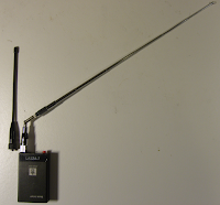
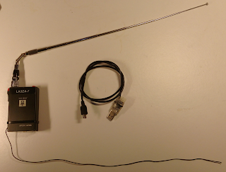
- Use a longer telescopic antenna. In the picture I have used an antenna that can be extended from 16.5 cm to 45.2 cm. Depending on how you use the tracker, always extend the antenna as much as practically possible.
- Add an external counterpoise or “tiger tail” of length a quarter of a wavelength. That’s about half a meter. In the picture it is fastened on the antenna’s BNC connector by means of an 8 mm ring terminal.
- Update the firmware, if you haven’t done so already, to the version from 3 Nov 2015. I have written before about my experience with that firmware.
- Get rid of the pirated USB chip in the interface cable. I did that last year and now interfacing it to the PC and updating it is so much simpler.
These simple steps have made my AP510 tracker much more useful.
The post “What it takes to make the AP510 APRS tracker useful” first appeared on the LA3ZA Radio & Electronics Blog.
 Latest firmware for AP510 APRS tracker is superb
I got my AP510 APRS tracker a little more than a year ago. It kind of worked, but not very well in my car. But after the tracker got a new firmware dated 3 Nov 2015, it has become so much better. Now I can say that it is really useful.
Apparently, the Smartbeacon function didn’t work properly in earlier versions of the firmware. With some good debugging and error reporting by KC5EVE, Mark, working with the software developer for the AP510, BG6QBV, the annoying errors now seem to be gone. This is all documented in the Yahoo AP510 group.
I have fitted mine with a 16-45 cm telescopic antenna and even when attached to one of the rear headrests in my sedan, the 1 Watt of output power tracks very well.
The map below shows a drive from Telemark, about 100 km west of Oslo, to Oslo with as good coverage as one can expect given the valleys and the availability of APRS digipeaters on the way.
 Latest firmware for AP510 APRS tracker is superb
I got my AP510 APRS tracker a little more than a year ago. It kind of worked, but not very well in my car. But after the tracker got a new firmware dated 3 Nov 2015, it has become so much better. Now I can say that it is really useful.
 |
| AP510 with original short antenna and telescopic antenna |
Apparently, the Smartbeacon function didn’t work properly in earlier versions of the firmware. With some good debugging and error reporting by KC5EVE, Mark, working with the software developer for the AP510, BG6QBV, the annoying errors now seem to be gone. This is all documented in the Yahoo AP510 group.
I have fitted mine with a 16-45 cm telescopic antenna and even when attached to one of the rear headrests in my sedan, the 1 Watt of output power tracks very well.
The map below shows a drive from Telemark, about 100 km west of Oslo, to Oslo with as good coverage as one can expect given the valleys and the availability of APRS digipeaters especially in the western part.
 |
| Note the missing tracks east of LA5PPA-1 which are due to a 3.5 km long tunnel, Strømsåstunnelen, between Drammen and Mjøndalen. |
 Finally got rid of the pirated USB chips for the UV-5R and the AP510
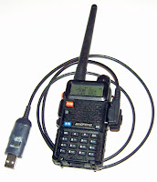
Both the Baofeng UV-5R handheld UHF/VHF radio and the Sainsonic AP510 APRS tracker come with interface cables with pirated chips. These are clones of Prolific USB/serial chips. Since Prolific has taken measures against this, only old drivers will work with them. That means that one has to stop automatic driver updates as explained on the Miklor site for the Baofeng UV-5R. The same is true for the AP510. This is a nuisance.
I got tired of this and got myself some USB/serial modules from Ebay based on the CP2102 chip instead. The cost was US $1.43 a piece so it should be affordable for anyone. I also got some clear heat shrinkable tube.
It wasn’t too hard to follow the instructions on the Miklor site. I ended up replacing the chip in the original Baofeng serial cable. I’m a hardware guy so I think it is a shame not to see the three LEDs for power, rx, and tx so I used my Dremel to make a 12×12 mm cut-out in the original case, and then I closed it by using transparent shrinkable tube. For a picture, see the top of the first image.
If it doesn’t work the first time, exchange rx and tx and see if that works better. According to this site, the boards can be marked just opposite of what you might think.
The Sainsonic AP510 APRS unit has a cable that on first sight just looks like a standard USB cable, but it also contains such a chip. Here I made a completely new cable without any case. It is important that 5 Volts also passes through as this is used for charging. The pinout can be found on the site of DJ7OO (use Google translate if needed). I enclosed the board in shrinkable tube which is transparent enough for the LEDs to shine through as seen in the bottom of the first image. The board with the fake chip is found in the middle.
 So now I have interface cables for both units that don’t require me to stop updates of drivers or any other special precautions and it is much easier to program the devices from any PC.
 Finally got rid of the pirated USB chips for the UV-5R and the AP510
Both the Baofeng UV-5R handheld UHF/VHF radio and the Sainsonic AP510 APRS tracker come with interface cables with pirated chips. These are clones of Prolific USB/serial chips. Since Prolific has taken measures against this, only old drivers will work with them. That means that one has to stop automatic driver updates as explained on the Miklor site for the Baofeng UV-5R. The same is true for the AP510. This is a nuisance.
I got tired of this and got myself some USB/serial modules from Ebay based on the CP2102 chip instead. The cost was US $1.43 a piece so it should be affordable for anyone. I also got some clear heat shrinkable tube.
It wasn’t too hard to follow the instructions on the Miklor site. I ended up replacing the chip in the original Baofeng serial cable. I’m a hardware guy so I think it is a shame not to see the three LEDs for power, rx, and tx so I used my Dremel to make a 12×12 mm cut-out in the original case, and then I closed it by using transparent shrinkable tube. For a picture, see the top of the first image.
If it doesn’t work the first time, exchange the rx and tx connections and see if that works better. According to this site, the boards can be marked just opposite of what you might think.
The Sainsonic AP510 APRS unit has a cable that on first sight just looks like a standard USB cable, but it also contains such a chip. Here I made a completely new cable without any case. It is important that 5 Volts also passes through as this is used for charging. The pinout can be found on the site of DJ7OO (use Google translate if needed). I enclosed the board in shrinkable tube which is transparent enough for the LEDs to shine through as seen in the bottom of the first image. The board with the fake chip is found in the middle.
 So now I have interface cables for both units that don’t require me to stop updates of drivers or any other special precautions and it is much easier to program the devices from any PC.


