Posts Tagged ‘Construction’
 VK on a whip antenna
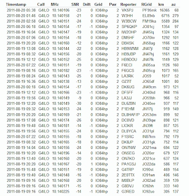
The amazing power of the WSPR mode to enable weak signals to be received over long distances was demonstrated conclusively when my 2 watt signals, transmitted into a 1.3m long telescopic whip antenna from inside the G4ILO shack,were received in Australia and the USA, not once but several times with SNR reports of up to -19dB.
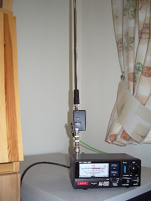
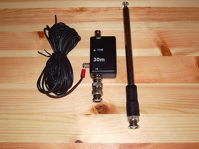
These spots were not achieved using a hand held radio as they occurred early in the morning when I was asleep. But they were made using a home made portable 30m whip antenna that I designed to be used with the VCXO-AXE portable WSPR transmitter I recently built. Here is a picture of the antenna taken during the tests.
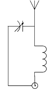
The antenna consists of an L-match mounted in a small plastic project box, with BNC sockets for the transmitter and the whip antenna.
The constructional details can be gleaned from this internal view here. Click the image to see a much larger version.
The loading coil consists of about 46 turns of 28SWG wire on a T80-6 toroid. The matching capacitor is a 4 – 40pF trimmer. The number of turns was determined empirically (i.e. using trial and error) so don’t ask me for details of how to make one for other bands. There may be formulas for calculating things like that but I don’t know them.
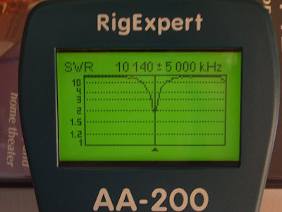
It would have been difficult to make this antenna without an antenna analyzer like my RigExpert AA-200 which displays the SWR across a range of frequencies graphically. With my first attempt at the inductor it was possible to obtain an SWR null at 10.140MHz but it was rather a broad dip and the minimum was around 3:1. However at lower frequencies I saw that I was able to obtain a much deeper, sharper null. This made it clear that what I needed to do was remove some turns until the deep, sharp null was at the frequency I wanted. A deep null indicates higher Q and therefore better efficiency.
You can see the SWR curve of the final version below.
Note, however, that this was taken inside the shack in the test position where reflections spoiled the SWR and broadened the dip. When measured out of doors the SWR curve dipped deeper and was narrower as long as I stood clear of the antenna. (It was interesting to note how the SWR was affected even if I was a metre away from the telescopic whip. This suggests efficiency would be adversely affected when used in true hand held fashion.)
A good ground or quarter wave counterpoise wire is needed with this antenna. The resonant frequency is affected by the ground system used as well as the length of the whip and the position of the trimmer. If you don’t want to take an antenna analyzer to the field to check and tune the antenna before operation you should use the same counterpoise. So it would be advisable to pair the counterpoise with the antenna.
Further tests would be useful to determine the extent to which a good match is reproducible in different locations using the same whip length and counterpoise without retuning.
In case retuning is needed I added an access hole for the tuning trimmer. The resonant frequency can also be changed (increased) by shortening the telescopic whip a section or two.
This has been an interesting project. As a result of it I now have a completely portable, pocketable, battery powered system capable of sending a radio signal half way round the world, and I have developed a useful monoband 30m antenna.
 Whispering with a VCXO-AXE
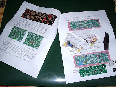
My VCXO-AXE WSPR transmitter kit from W5OLF came this morning. It was two weeks in the post, doubtless due to Customs which had opened the package. I wasted no time in building it, though it did take me somewhat longer to complete than it took AE5X.
The kit itself has been impressively put together. The PCB is extremely high quality and the instructions are almost of Elecraft standard. If the horrible Spectrum Communications Off-Air Frequency Standard kit had been produced to this level of quality it might not have turned out to be a failure for me. If American kit makers can produce nice silk screened and solder masked boards, why do ours make us struggle with boards that look like they were made by hand on somebody’s kitchen table?
The VCXO-AXE kit uses almost all through hole components and there is plenty of space around the solder lands. I doubt that anyone would have any trouble building this. The one part that induced a feeling of terror when I saw it was the VCXO itself.
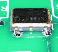
As described, it is a “larger surface mount component.” But what I didn’t expect was that it didn’t have any pins or legs that stick out to solder to. Instead, you have to solder it so the solder goes under or up the side of the chip. You need a very fine tipped soldering iron for this. I couldn’t really see if I had successfully soldered the chip or not, so I took a couple of pictures.
The result is not very pretty, but it must have been OK because the transmitter eventually worked!
When ordering, I specified my call, locator and the supply voltage I would be using (12V, as I planned to power the transmitter off a pack of 10 NiMH batteries.) The PICAXE controller chip came programmed with this information and a power level of 33dBm – 2 watts.
On a freshly charged battery pack I was actually getting nearer 3 watts output once the PA tuning capacitor had been peaked up, but after the first few transmissions the power did drop off a bit to become nearer the advertised 2 watts.
I hooked the VCXO-AXE up to my attic MFJ magnetic loop, watched the radio-controlled clock in the shack until it rolled over to an even minute, pressed the transmit button and a couple of minutes later had my first WSPR spots.
Soon after that I had several more. No great DX, but perhaps that is just down to conditions at the moment.
The instructions warn that second harmonic suppression of this transmitter is not great and an external low pass filter is advised. However, the magnetic loop (either the MFJ or my portable Wonder Loop) has a very high Q which I am sure does a good job of attenuating out of band harmonics on its own.
My next move will be to build the little transmitter into a plastic box and use it as a hand held portable WSPR rig. It would be fun to try making a 30m base loaded whip – which should also be fairly high Q – and see how well that works. So expect some WSPRing from various locations around Cockermouth some time soon!
This was a fun project and a good morale booster to prove to myself that I can still build stuff – and with an SMT part in it, too! Thanks to Jay W5OLF for making the kit available. A 20m version would be nice, as well!
If you want to buy one of these kits for yourself you have to look on eBay, though as of right now there doesn’t seem to be any for sale.
 K2 audio switchbox
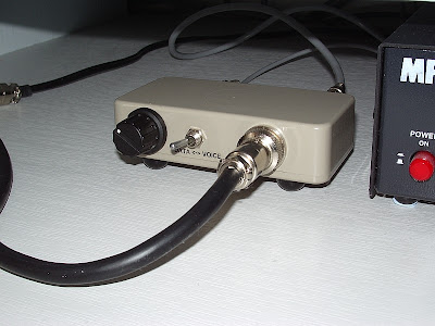
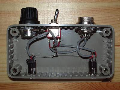
My vision and steadiness of hand have improved to the point that I am able to build projects! Here is a picture of a switchbox I made for my Elecraft K2 a couple of days ago which allows me to switch the audio input source from the microphone to the computer sound card.
One of the niggling annoyances of the K2 is that it does not have separate inputs and outputs for voice and data modes. Most users carry out one of several published mods to obtain a fixed level audio output for the computer. Mine is tapped off the KAF2 filter module and runs to an RCA phono socket on the back panel. But for transmit most people just swap the mic lead and data lead over.
I used my K2 like that for years, though it wasn’t a great hassle mainly because I hardly ever used a microphone anyway. But I finally decided to come up with a better solution – hence the switchbox. It was easy to make and I thought it would be within my capabilities. Here is a picture of the internals.
In one position of the front panel switch the microphone signal is switched straight through. In the other, the audio comes from the computer sound card headphone output via a potentiometer. Since taking that picture I added some resistance to the hot side of the pot so the control can be used over a greater range as the K2 mic input is very sensitive and needs some attenuation. As you can see, I don’t bother with isolating transformers. I’ve made dozens – well at least a handful – of computer/radio interfaces in my time and I have never, ever found the need for one. YMMV.
To celebrate the restoration of my constructional skills I have ordered a W5OLF WSPR beacon kit. John Harper, AE5X, recently reviewed it and wrote that it took him 50 minutes from starting to build to receiving his first spot. So I figured it shouldn’t be too difficult, though it will probably take me longer than 50 minutes. It would be nice to successfully complete a kit before I start undergoing the treatment that I expect will make me too tired to do all the stuff I am managing to do at the moment.
 UV-3R programming cable
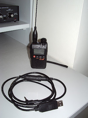
Today I made a programming cable for the Baofeng UV-3R. Until now I couldn’t be bothered, as the radio is easy to program manually and neither the cost of sending off for a programming cable nor the complexity of building one of the programming interfaces published on the web seemed worthwhile. But it turned out to be very easy.
A few months ago, with other purposes in mind, I ordered on eBay two USB/TTL/RS232 cables. If you search eBay for “PL2303” you should find a couple of sellers: one from Hong Kong is currently selling a single cable with free shipping for £3.99. These are USB plugs with the serial converter built in to the plug. At the other end there are four wires: GND, TXD, RXD and +5V. The logic level is 3.3V (at least mine are) so it can be used directly with the UV-3R. Just solder the appropriate wires to a 4-way 3.5mm jack plug.
The connections (and the wire colours for my cables) are:
- GND (black) – base of the plug
- TXD (green) – first ring
- no connection – second ring
- RXD (white) tip
Cut off the red +5V wire and make sure it doesn’t short out against anything.
In the photo you’ll see that there is something else in the middle of my cable. That’s because I used a 4-way 3.5mm to mini-DIN adapter sold for use with various Yaesu radios such as the VX-1R, VX-3R, VX-5R, FT-60R and VX-150 instead of a simple plug. I bought that at the same time I bought the radio as I thought it might be useful if I wanted to try connecting other things such as a TNC. Plus the simple 4-way 3.5mm jack plugs are a bit hard to find.
Mini-DIN plugs can be a bugger to solder, especially with my hands shaking as they do now. But the inline socket I used today had terminals that would hold the tinned end of a thin wire pushed into it even without soldering, which made the job easy for me.
I tested the new cable with the UV-3R programming software and it worked, so that was a good result.
By the way, I saw on the UV-3R Yahoo group that the free cross-platform cross-radio programming tool CHIRP will soon be supporting the UV-3R. I can claim a little bit of credit for that as I was instrumental in persuading a UV-3R user who had been investigating the programming protocol to share his findings with CHIRP’s author. So soon you’ll be able to upload memories from other radios into your UV-3R.
 OAFS failure
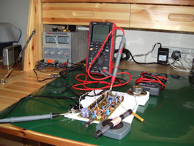
One of the things I had intended to do this year was install the external frequency reference module in my Elecraft K3 in order to get the best possible frequency accuracy for digital modes. To this end I had ordered an Off-Air Frequency Standard (OAFS) kit from Spectrum Communications so as to avoid wearing out my rubidium frequency standard. I had completed populating the OAFS board a couple of weeks before I ended up in hospital. So I thought I would try to see if it worked, as that would simply involve connecting up a speaker, ferrite rod antenna and power supply.
It began to look as if the predictions of the couple of people who commented or emailed when I first posted about the OAFS were going to be right. I could hear BBC Radio 4 long wave in the loudspeaker but it was very weak, presumably (as I had been advised) due to North Cumbria being a poor location to receive the transmission. When I checked the frequency of the phase locked loop it remained steadfastly on 216.4kHz regardless of the setting of the trimpot.
The instructions supplied with the kit suggested that it might be necessary to change a resistor value if the loop will not lock on to 198kHz so I wrote to Tony Nailer at Spectrum to see if he had a suggestion. Unfortunately his reply was that if the loop will not change frequency with the pot there must be a solder bridge or other assembly error. I checked my soldering as best I could and re-did any joints that looked suspect but the way my eyes are now any sort of cross checking between the schematic and the circuit board to look for errors is impossible.
I haven’t really figured out what is wrong with my eyes but it is as if they no longer have the ability to vary focus. I can only see clearly what is at the exact focal point of whatever spectacles I am wearing. When something is out of focus my head swims and I have to close my eyes for a few minutes to steady it again. So any sort of constructional work now is well-nigh impossible.
Tony offered to get the OAFS working for me for a fee if I sent it to him, but at this point I think it would be a waste of money. I can’t see myself installing the frequency reference boards in my K3 now even if I still had the same interest in doing so. So I think the OAFS is destined for the G4ILO junkbox.
 Off-air frequency standard
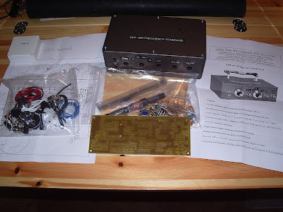
This is an unbuilt kit for an Off-Air Frequency Standard from Spectrum Communications. It is a crystal calibrator phase locked to BBC Radio 4 on 198kHz with an output of 2V peak to peak at 10MHz.
I got this with the intention of using it to frequency lock my Elecraft K3 using the KREF3 module. Regular readers may remember that last year I purchased a surplus Efratom LPRO-101 rubidium frequency standard to calibrate my radios. But a rubidium frequency standard has a finite life which will be used up very quickly if it is turned on all day to use as a real-time frequency reference. My intention is that the off-air frequency standard will run all day and keep my K3 as accurate as I need it to be.
I ordered the full kit from Spectrum. I was disappointed to find that what looked like a die cast box in the picture is actually a plastic box with a grey metallic finish. If I had realized it was not a die cast box I would probably have opted for the cheaper PCB kit and ordered one of the nice extruded aluminium alloy Hammond cases for the project. I hope it will be RF-proof enough to work in my shack environment where up to 100W may be used into indoor antennas.
The other disappointment was the rather home made looking PCB which does not have a silk screened component overlay. There is a printed layout in the instruction sheet but relating the component positions to the holes on the PCB is easier said than done. My initial thought was that I am not going to be able to build this. What I will have to do is draw the component overlay on to the PCB itself prior to construction. But it isn’t easy with my diminishing eyesight and need to use different strength lenses which makes switching between things at different distances a real trial. Having a silk screened PCB would just have made things a bit easier. I think my days of kit building are definitely numbered.
