Posts Tagged ‘Duga Array’
 Remembering The ‘Woodpecker’
Those of you that have been hams for a long time will no doubt recall the Russian 'Woodpecker'. The 'Woodpecker' was a strong, fast repeating signal / racket that often wiped out amateur communications on 20m here in North America ... maybe other parts of the world as well.
Amateurs with yagis eventually determined that the signals (yes there was more than one it seemed) were coming from the USSR. The QRM was persistent and in spite of formal complaints being lodged via diplomatic channels, continued for many years ... from 1978- 1989. Some of the new transceivers built during the time actually had a 'WOODPECKER' position on the noise blanker switch, hopefully offering some relief to the problem.
For you younger folks, here's what Duga usually sounded like:
Several web searches brought up numerous descriptions of the Duga (Russian for 'arc' or 'bow') project, some with conflicting information. From what I can sort out, there were three Duga sites ... one near Chernobyl, another near Chernihiv and a third, much later, in Siberia. The first two (Duga and Duga-1) were in the Soviet Ukrainian SSR (now Ukraine) while the third was located near Komsolmosk-on-Amur in the Russian far east. One source indicates that the second Chernobyl site is often misidentified as the Duga-3 array and should be referred to as Duga-1, with Duga-2 being the Siberian location.
Initial speculation suggested this intrusive signal was some form of 'jammer' ... very common during the Cold War. It wasn't long before the true nature of Duga was thought more likely to be an 'over-the-horizon' (OTH) long-range radar system for detecting the launch of North American missiles aimed at the USSR. The three radar sites gave the Soviets good over-the-pole coverage as well as to the east, where it could also be utilized for tracking domestic rocket launches.
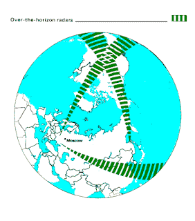 |
| courtesy: http://www.globalsecurity.org/wmd/world/russia/steel-yard.htm |
The antennas themselves appear to be phased dipole curtain arrays, commonly used in various configurations by shortwave HF broadcasters.
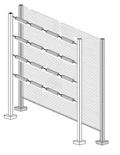 |
| courtesy: http://www.antenna.be/hr.html |
Each site was paired with a receiving array ... remember, this was a radar system, with two of the three systems having the receiving array located tens of kilometers from the transmitter. The Chernobyl Duga is said to have had the receiving antenna located on site. Sources discussing physical size indicate the dimensions for the receiving array to be larger than those of the transmitting antenna. It seems possible then, that the pictures and videos commonly found are those of the receiving array and not of the transmitting antenna. It might make sense to have more gain on 'receive' than on 'transmit' as echoes from small targets many thousands of miles away would not be easy to detect. No matter what the actual case, I can only imagine the fun of hooking up an HF transceiver to one of these arrays during a DX contest on 20m CW!
The Chernobyl site shows two arrays, side-by-side ... possibly the larger being that used for receiving and the smaller one for transmitting. This antenna has been noted as a 30/10/2 array ... 2 bays, 30 dipoles wide and 10 high, 600 elements in all!
Further research tends to indicate that each dipole is what is called a 'Nadanenko' dipole. The main feature of this style was its cage-styled construction, giving the element a large diameter resulting in a broad bandwidth.
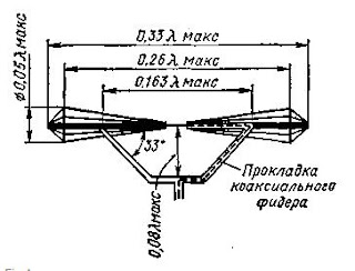 |
| courtesy: https://shema.info/en/antenna/ |
 |
| courtesy: englishrussia.com |
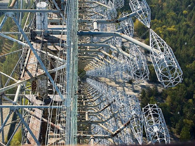
First, you see that there are two sets of arrays 15 driven elements wide by 10 driven elements high for a total of 600 elements! They are intermeshed and offset from each other by 1/2 wavelength both vertically and horizontally. There is a horizontal wire screen reflector behind the driven elements.
Some of the other things I noticed are ...
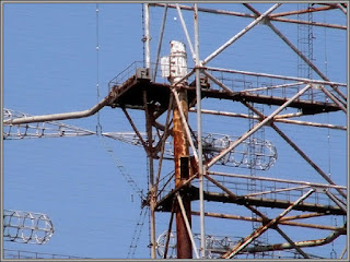
... you can see the open-wire feeds and reflector screen. Each set of collinear elements is fed individually with open wire line. There is a support line between each two bays of driven elements.
... that the reflector screen is supported on the sides by the stand-alone free-standing towers at each side of the array. (I had been wondering why they would have those towers next to the array like that. Now I know.)
... that the element supports are steel pipe instead of fiberglass (or something similar). Apparently, the shape of the radiators allows for the pipe supports to enter the element cages at the element low-impedance point which made the supports invisible to the antenna and also allowed for the supports to not radiate themselves.
 |
| courtesy: http://anzee.livejournal.com/65530.html |
The Duga system was operative between 7 and 19MHz, with 40kHz wide pulses, usually lasting for about seven minutes. The most common pulse rate was at ~10Hz but this sometimes varied. Power levels used often mention 10 megawatts but it's not clear if this was RF output, peak pulse power or ERP.
It's somewhat gratifying after all these years, to actually see close-up, where the Woodpecker signal started its journey around the world and to appreciate the superb engineering that went into these impressive structures ... but sad to see the last one in such a rusted state of decay and abandonment. It would be nice to hear it just one more time ... but please, only for a couple of minutes.


