Posts Tagged ‘homebrew’
 Better with SMA
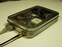
I had some trouble closing the lid on the “Just good enough 10 MHz GPS reference” due to the size of the BNC jack. Therefore I changed it to an SMA (SubMiniature version A) female jack. A thin cable connects it to the K3’s SMA input and there is no need for any SMA-BNC adapter on that end.
At the same time I moved the GPS antenna to a more central location in the tin, in the hope that the walls of the tin would interfere less with GPS reception. That’s the theory anyway, if it matters much in practice is a different story.
 Actually, I think I’m going to use SMA more often with these clear top tins and also Altoids tins. They take up much less space and are easier to install and to work with.
There aren’t any high power applications for circuitry in such tins, so I cannot so any reason why the SMA won’t work just as well or even better than the BNC.
Other related posts about the 10 MHz reference:
- Just good enough 10 MHz reference (3 Oct 2015)
- Curing amnesia in the 10 MHz GPS reference (19 Nov 2015)
- Improved GPS reception with a ground plane (11 April 2016)
 Better with SMA
I had some trouble closing the lid on the “Just good enough 10 MHz reference” due to the size of the BNC jack. Therefore I changed it to an SMA (SubMiniature version A) female jack. A thin cable connects it to the K3’s SMA input and there is no need for any SMA-BNC adapter on that end.
At the same time I moved the GPS antenna to a more central location in the tin, in the hope that the walls of the tin would interfere less with GPS reception. That’s the theory anyway, if it matters much in practice is a different story.
 Actually, I think I’m going to use SMA more often with these clear top tins and also Altoids tins. They take up much less space and are easier to install and to work with.
There aren’t any high power applications for circuitry in such tins, so I cannot so any reason why the SMA won’t work just as well or even better than the BNC.
 More VE7 Lightwave Activity
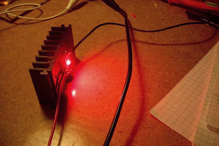 Two more VE7's are well on their way to getting in on the lightwave fun in the Vancouver lower mainland region. Toby, VE7CNF, and Mark, VA7MM, are constructing stations similar to the ones built by myself and Markus, VE7CA.
Toby and Mark live close enough that a clear-air scatter QSO between them might also be a possibility. Having another near-by amateur, or even in the same city, is a great source of motivation ... not to mention having someone else to actually talk to, once the system has been built.
Except for the LED focusing sled, Toby's fine-looking transmitter box and LED driver / modulator, are now complete. The receiver is next on the list. I believe this will use one of the inexpensive ($5) fresnels lenses, purchased locally at Princess Auto, that seems to work very well for the price.
| photos courtesy VE7CNF |
 Clear Air Scatter Tests On 458THz
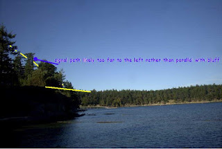
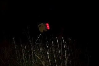 After patiently waiting for the bright moon to clear the early evening skies, I was finally able to venture out for my first clear-air scatter test this past Sunday night. I had plotted the path on my Mayne Island map and determined bearings as best I could, but the path was going to be very tight. If the path plan was right, my signal should just clear the high beachfront bluffs at the chosen sea-level receiving site.
After carefully aiming the light, I set off for the receive site at around 7:45PM and was all set up with the new lightwave receiver about 30 minutes later. The site appeared fairly quiet and the Argo screen confirmed that there was little QRN coming from the local houses up on the bluff. I listened for over an hour, trying various slow changes in pointing ... varying the azimuth a few degrees at a time, and then the elevation. Unfortunately not the slightest indication of my ~549Hz tone was seen. I was confident that the system was working as several strobes were heard from distant aircraft (near Vancouver), as their flashing lamps skimmed the edge of the far treeline.
It seems likely that either my aiming or bearing calculations (or both) were off and that the signal was probably slightly to the west of me, with the bluff blocking any hope of reception ... I knew it was going to be close but was hoping for a little luck.
I left the transmitter outside overnight (it was set up two properties to the SE) and decided to try a second shot on Monday night. This path, although shorter by a mile, would require the signal to pass over two high hills ... the first topping out at 667' and the second at 567'. The overall direct-path distance was 1.7 miles (2.7 km). A cross-section of the signal path is shown below as it hugged the edges a little lower than the peaks:
 |
| courtesy: http://www.heywhatsthat.com/profiler.html |
I have been using a 'compass' app on my I-Pad to determine directions when aligning the transmitter and receiver setups. I'm not 100% convinced of its accuracy at all times, as readings can sometimes be a bit flaky. Before doing any more testing, I'll need to solve this, either with a better app or with a real compass.
The transmitter was set up just before darkness, pointing right at the edge of the treeline along the 667' ridge and elevated at a 28 degree takeoff angle. The deep-red, 640mw LED, was switched-on just before departure at around 8:30PM.
It didn't take long to get set up in the back of the CRV, with the receiver temporarily set in no particular direction and plugged into the computer.
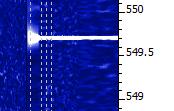
When Argo came to life, I went to the front of the car to grab the I-Pad so that the receiver could be aligned but was surprised to see a bright line at 549Hz when I came back! It seems that my 'rough' placement of the receiver was spot-on, and not exactly where I had originally intended. In fact, there appeared to be about a 10 degree error in where I had planned to point. I later traced the error to my path drawn on the paper map as it was difficult to determine my exact receiving location on the older map, which didn't show the new road where I had set up on.
 |
| Monday night's path |
With the strength of signals recovered on this path, two-way communication could have easily been established on any of the CW QRSS modes ... if quieter, probably on normal audible CW. Signal strength indicated that there was still plenty 'left in the bucket' for greater distance paths, probably much further than I am able to test here on the island.
This was the first thing I saw, at the QRSS60 mode in Argo ... a fairly narrow passband and a ~25+ db dig into the noise.
Backing off to a wider bandpass (less sensitive) but faster QRSS10 mode showed the signal still very apparent:
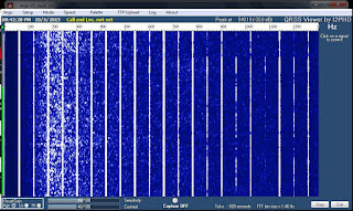
The almost 'real time' QRSS3 mode, although showing a much weaker signal, indicated that the signal would have been almost audible had it not been for the high level of background noise at this site. Don't confuse the lightwave signal with the much stronger 9th harmonic of 60Hz on 540Hz!
The ferry terminal was just down the hill about 1/2 mile and with several kilowatts of spectrum-polluting 60Hz sodium vapor lighting, the cloudy skies were a sea of bright-pink. There was a high level of audible hum in the phones, right from the start, that unfortunately, masked any hope of an audible detection. The waterfall screen capture shown below, illustrates the massive QRM at this otherwise nice site!
The night was not going to be complete without a strobe signature, captured on Argo from a high passing jet aircraft:
 | |
| strobes |
All-in-all, it was a very successful outing, considering the obstructed path and the $5 fresnel lens used in the portable receiver! I've examined the island map for any other possibilities and there are not many suitable candidates. I had hoped for one other possibility towards the west, which would stretch the path by almost another mile, but I'm not really sure that I can get a clear shot without hitting the very close treeline at this end.
I think the next round of testing will be in the other direction ... across Georgia Strait, with John, VE7BDQ, who has expressed interest in doing some deep overnight Argo searches for my signal in the clouds.
I'm not sure which mode would offer the best chance ... 'clear air scatter' or 'cloudbounce'. John has a very good receiver, with a slightly larger and better-quality fresnel than the one used in these tests. Working from his suburban backyard, directly across the strait at 13 miles (21 km) distant, his direct path to me is somewhat obstructed and will require an elevation angle of around 30 degrees at his end. I think, ideally, we would both like to be skimming just above the ocean, with only a slight elevation. A lower and less obstructed shot from his yard would mean an oblique path so this also remains a possibility. We will play with what we have and hope for the best ... even just a trace of signal would be a measured success.
I think that a non-line-of-sight (NLOS) contact would make an exciting challenge and a great project for two amateurs living in the same city or town, and ... you really don't even need a ticket!
For more technical details on the equipment used in this test, see "A West Coast Lightwave Project" describing the activities between here and Markus, VE7CA. We have just learned that this article will be published in the 2016 Radio Amateur's Handbook ... hopefully inspiring more new lightwave activity!
 More Manhattan Building Tips
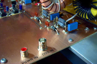 |
| 2200m kW Transmitter |
One of my early blogs described how I make the pads needed for Manhattan style. It can pretty much be used for any modern project and has been used here for countless circuits ... from a 1W LF tranmsitter to my 2200m/630m kilowatt.
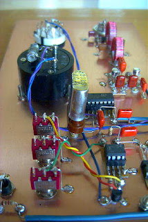 |
| 1W LF Transmitter |
I found these hints from Bob about pads and soldering components particularly helpful for anyone making a start in Manhattan style building:
Round pads require only placing in proper X and Y coordinates. A rectangular or square pad also requires proper rotation. A rectangular pad placed cockeyed doesn't look good.
I've had good luck with pads made from .032 double sided board. Solder surface tension prevents shorts with this pad thickness. My experiments making pads from thinner .010 thick flexible board often resulted in shorts.
A clean surface is needed for good pad adhesion to the board. I polish the pad board on both sides to a shine and then punch out the pads.
Pads can take up a lot of solder so I prefer to use 1/8th inch (.125) diameter pads.
Some of my Manhattan projects have failed because pads have loosened from the board. Cheap, discount super glue was my mistake. I now use Loctite Super Glue Gel. Of the hundreds of pads I've applied, I've never had one loosen.
If a punch is used to make pads each pad will have a rounded side and concave side. My pads are applied rounded side up. Using tweezers, I pick up a pad, place a small dab of glue on the punch mark and drop the pad in place. Light tweezer pressure is used to set the pad. Too much pressure squeezes out the glue leaving a weak joint. I Use enough glue so it squeezes out around the bottom edge of the pad.
Disaster occurs if glue gets on the tweezers. Pads stick to tweezers and won't stick to the board. If this happens, I stop and wipe off the tweezers with a cloth. I also use an Exacto knife to remove any hardened glue on the tweezer tips.
I try not to put too many leads to a pad. For example, its common for a transistor base lead to connect to two resistors and two capacitors. If this happens I extend the transistor base lead across two adjacent pads ans share the connections between the two pads.
I take time to shape my component leads. I make certain I don't have to flex a lead, like a spring, to solder it in place. Improper technique means the next component soldered to the pad may spring loose the earlier lead.
I put a bend in the component lead so the lead sets level on the pad. But the bend doesn't need to be long. A bend a 1/16th inch long, or half the diameter of the pad works well. This also means multiple leads can attach to a pad, each pointing toward the pad center.
My Hakko 936 soldering station is rated for 50 watts. I use a wide tip to get that power to the pads. I'm surprised how much power is required to do Manhattan construction. This is especially true when soldering component ground leads to the project board.
It is very easy to come away with cold solder joints. After all the leads are attached to a pad I Heat all the solder on the pad to liquid state. My ground connections take 1-2 seconds and pad connections take about 1 second. I've had no damage to components due to the heat I apply.
I prefer to use .032 leaded solder for my pad connections. But I use .062 solder for ground connections or to fill in a heavily populated pad.
I offer these ideas for what they are worth to you.
bob-N7SUR
Bob also mentioned that he prefers to tape down a full size plan of his component layout as an aid in placing his pads ... a light punch mark through the paper layout, marking the pad's location. I haven't gone this far with any of mine, preferring to place pads as I build, giving flexibility to component placement.
There are lots of good online references for Manhattan-style building but be warned ... some of them, particularly the pages of Dave, AA7EE, will have you making plans and reaching for the soldering iron before you know what's happened!
 Just good enough 10 MHz GPS reference
Some time ago I noticed that the Ublox Neo-7M GPS has a 10 MHz output which is locked to the GPS system’s accuracy. Most people kept saying how useless it was due to excessive jitter unless it was cleaned up with a phase locked loop of some sort.
At about the same time I installed the external reference input for my Elecraft K3. The K3EXREF enables the K3’s frequency to be locked to an external 10 MHz reference. What struck me was how its function is described:
- The frequency of the internal oscillator of about 49.38 MHz is continuously measured and averaged, obtaining a value to the nearest 1 Hz.
- The K3EXREF does not phase lock the K3’s reference oscillator and the external 10 MHz source has no impact on the K3’s phase noise performance.
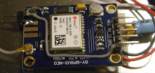
This got me wondering if the Neo-7M would be just good enough as a reference and that all the averaging internally to the K3 would take care of the jitter. I ordered one from Ebay for USD 12-13 together with an USB interface (USD 1.5) and hooked it up. (Actually the NEO-7M already has a built-in USB interface, but my board doesn’t support it). The result is shown above as assembled in a clear top tin. In my wooden house I can receive GPS indoors, so I have no need for an external antenna
 The K3 accepts the input and I see the star in REF*CAL blinking. Just after turn-on of the K3 my 49.38 MHz reference frequency ends in …682 and after 10-15 minutes it has fallen and stabilized to …648, i.e. 34 Hz down in frequency. This is just 8 Hz off the reference value I determined manually was the right one when my K3 was new in 2009 (49.379.640).
All this taken together indicates to me that the K3 finds this 10 MHz acceptable for locking. The measurement to the nearest Hz, implies a measurement time of the order of 1 second and that seems to be enough to smooth out the jitter from the Neo-7M.
In order to get this to work I had to do some modifications to the GPS unit. First I had to get access to the timepulse on the chip’s pin 3. My connection is inspired by that of G4ZFQ and consists of a small wire from the left-hand side of the 1k resistor to the upper left hole. From there another grey wire goes below the chip and to the 5-pin header which is soldered to the Vcc, Rx, Tx, Gnd pins. The 5th pin is cut off and is just attached to the other pins through the plastic hardware.
The second modification was required in order to get it to run from the somewhat noisy USB 5 Volt supply. That took some decoupling between the Vcc and Gnd pins (220 uF and 0.1 uF in parallel), visible to the right in the image above, using good engineering practice to keep the wires as short as possible.
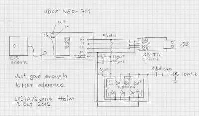
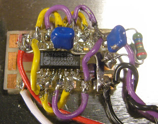 The timepulse is a 3.3 Vp-p output which cannot drive anything below 400-500 ohms impedance. Therefore I added a 74HCT04 driver that I have assembled on a little homemade SMD to DIL adapter PCB (easy to find on Ebay). It serves as a driver to feed the 10 MHz to the 50 ohm input of the K3EXREF.
The HCT04 IC has 6 inverters. One of them takes the input signal from the Timepulse output of the GPS IC and buffers it to drive the 5 other inverters in parallel. This is shown in the schematics at the end of this blog post.
The 5Vp-p output from the buffers is fed via 56 ohms to a connector that goes to the K3EXREF input. This is in accordance with the K3EXREF manual which says: “The 10 MHz source should have a signal level between +4 dBm and +16 dBm, nominal. For square wave sources, 2VDC to 3.3VDC peak is optimum. If the source is a 5V logic level, use a 50-ohm resistor in series with the input.“
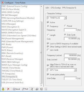 In order to set up the GPS I have used the u-center program (Menu: View, Configuration View, TP5 (Timepulse 5)) from Ublox and set it up with the parameters shown to the right. It blinks at 4 Hz before the signal is acquired and then switches to 10 MHz. This can be observed on the green LED connected to the Timepulse output also as it switches from blinking to a half-lit status.
 See also
 Just good enough 10 MHz reference
Some time ago I noticed that the Ublox Neo-7M GPS has a 10 MHz output which was locked to the GPS system’s accuracy. Most people kept saying how much jitter it had and how useless it was unless it was cleaned up with a phase locked loop of some sort.
At the same time I got the 10 MHz reference input for my Elecraft K3 (K3EXREF). What struck me was how its function was described:
- The frequency of the internal oscillator of about 49.38 MHz oscillator would be continuously measured and averaged, obtaining a value to the nearest 1 Hz.
- The K3EXREF does not phase lock the K3’s reference oscillator and the external 10 MHz source has no impact on the K3’s phase noise performance.
This got me wondering if the Neo-7M would be just good enough as a reference and that all the averaging internally to the K3 would take care of its jitter. I ordered one from Ebay for USD 12-13 together with an USB interface (USD 1.5) and hooked it up. The result is shown above as assembled in a clear top tin. In my shack I can receive GPS indoors, so I have no need for an external antenna
 The K3 accepts the input and I see the star in REF*CAL blinking. Just after turn-on of the K3 my reference frequency ends in … 682 and after 10-15 minutes it has fallen and stabilized to …648, i.e. 34 Hz down in frequency. This is just 8 Hz off the reference value I determined manually was the right one when my K3 was new in 2009 (49,379,640).
All this taken together indicates to me that the K3 finds this 10 MHz acceptable for locking.
In order to get this to work I had to do some modifications to the GPS unit. First I had to get access to the timepulse on the chip’s pin 3. My connection is inspired by that of G4ZFQ and consists of a small wire to the upper left hole. From there another grey wire goes below the chip and to the 5-pin header which is soldered to the Vcc, Rx, Tx, Gnd pins. The 5th pin is cut off and is just attached to the other pins through the plastic hardware.
The second modification was required in order to get it to run from the somewhat noisy USB 5 Volt supply. That took some decoupling between the Vcc and Gnd pins (220 uF and 0.1 uF in parallel), visible to the right in the image above, using good engineering practice to keep the wires as short as possible.
 The timepulse is a 3.3 Vp-p output which cannot drive anything below 4-500 ohms impedance. Therefore I added a 74HCT04 driver that I have assembled on a little homemade SMD to DIL adapter PCB. It serves as a driver to feed the 10 MHz to the 50 ohm input of the K3EXREF.
The HCT04 IC has 6 inverters. One of them takes the input signal from the timepulse output of the GPS IC and buffers it to drive the 5 other inverters in parallel. This is shown in the schematics at the end of this blog post.
The 5Vp-p output from the buffers is fed via 56 ohms to a connector that goes to the K3EXREF input. This is in accordance with the K3EXREF manual which says: “The 10 MHz source should have a signal level between +4 dBm and +16 dBm, nominal. For square wave sources, 2VDC to 3.3VDC peak is optimum. If the source is a 5V logic level, use a 50-ohm resistor in series with the input.“
 In order to set up the GPS I have used the u-center program (Menu: View, Configuration View, TP5 (Timepulse 5)) from Ublox and set it up with the parameters shown to the right. It blinks at 4 Hz before the signal is acquired and then switches to 10 MHz. This can be observed on the green LED connected to the Timepulse output also as it switches from blinking to a half-lit status.