Posts Tagged ‘homebrew’
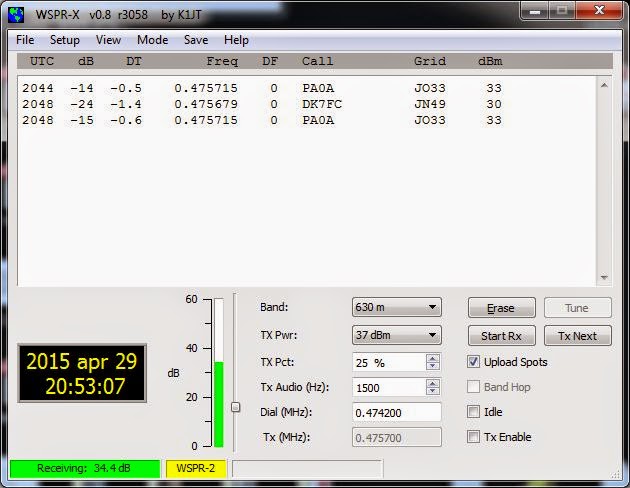
 First 475 kHz WSPR decoding
Tonight I made the first successful decoding of WSPR on the 630 m band. What inspired me was all the talk on the Elecraft reflector on the new synthesizer which in addition to having less phase noise, also allows the K3 to go below 500 kHz. I don’t have that synthesizer, but the discussion reminded me of the low frequency converter I built many years ago. It converts 0-1 MHz to 14-15 MHz. Using the KXV3 transverter interface of the K3 it was easy to interface and get up and running.
The first signals I decoded are shown in the water fall above, and their origin in Germany and the Netherlands is shown in the next figure.
According to WSPRnet, PA0A’s 2 Watt transmitter is 784 km away from me, and DK7FC’s 1 Watt is 1164 km away.
The converter is based on a 74HC4053 switch used as a mixer with a 74HC04 for a 14 MHz oscillator. It is based on SM6LKM’s design, but with a different oscillator frequency and a simplified output filter. It is one of many small projects that I have built in Altoids tins. The antenna used was my trusty old 80 meter horizontal loop with a 4:1 Elecraft balun.
Perhaps the next step is to finish the 475 kHz filter of my Ultimate 3 WSPR transmitter and see if others can receive me? That is going to be more of a challenge antenna-wise.
 New MOPA Completed
Well ... my new 1930's style MOPA transmitter is finally finished after several months of construction. I have also put together a page on my website describing the project.
For many years, December's high winds here on the coast, have always arrived coincidentally with the start of the annual 1929 QSO Party, making my signal dance around even more than usual! With the new MOPA, I'll no longer have to worry about high winds upsetting signal stabilty ... although many of us do enjoy hearing these musical sounds of '29!
By the way, there's still plenty of time for you also, to put something together for this annual fun event. You can see a whole page-full of inspiring '29 homebrew magic here (scroll to the bottom half) ... and there is plenty of help available for your project in the AWA Yahoo Builders Group ... we are always looking for more new activity, particularly here out west.
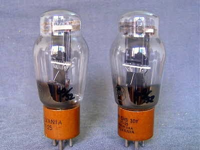 |
| courtesy: natubes.com/ |
I'm looking forward to working many of you in the next '29 QSO Party ... in the meantime, I'm thinking hard about what my next project might be!
 A Versatile 630m Antenna
Mark, VA7MM, had come up with a nicely-designed antenna that will serve as his main 630m radiator. Not only that but it can be used on 10m, 15m and 30m and 160m as well!
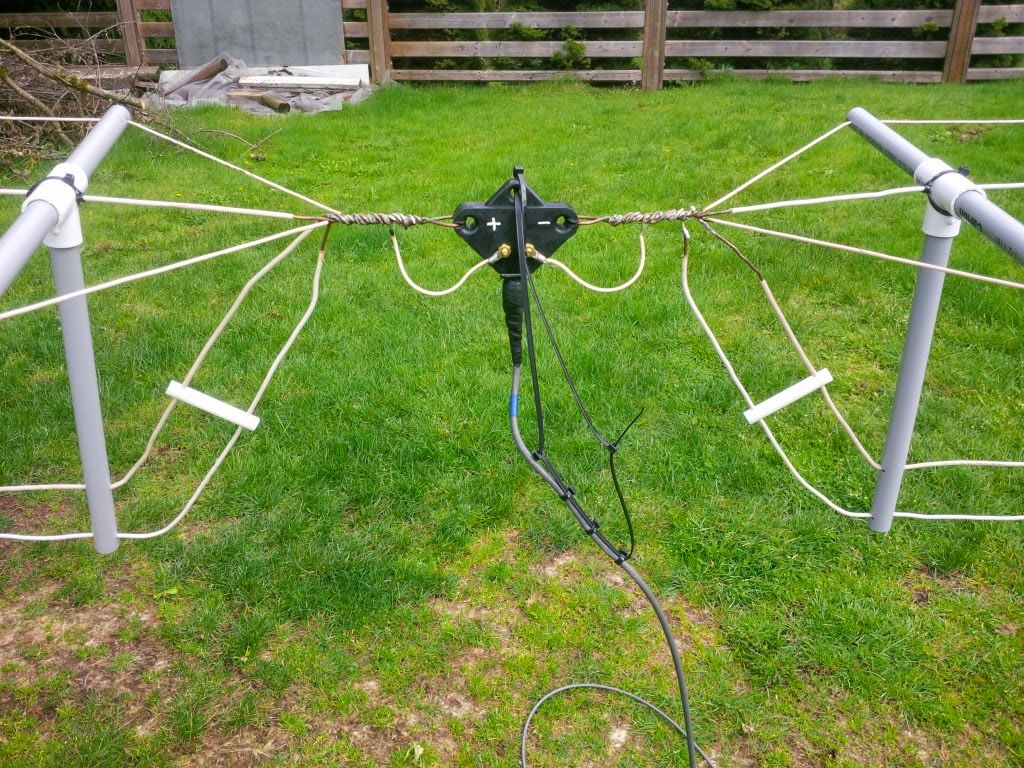
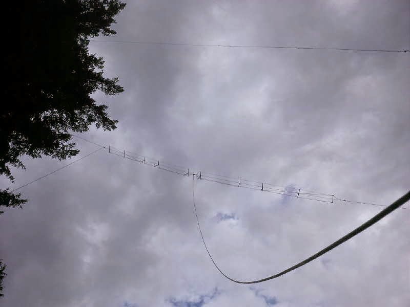
The antenna consists of a mini-flat top dipole, with three resonant dipole legs all terminating at a common feedpoint.
This can be used directly on any of the three high bands. Shorting the end of the coaxial cable, dropping vertically down from the feeedpoint, the dipole feedline becomes the vertical element of a top-loaded 630m 'T' antenna, 100' in the air.
With suitable loading coils and appropriate switching, the 'T' will also be used on 160m, making the versatile antenna work on five different bands ... a nice demonstration of basic antenna principles put into real practice!
 Low power longwave transmitter experiment
Many places in the world, low power transmitters in the medium wave band are allowed. I am talking about regulations like in the US where FCC part 15 allows up to 100 mW input.
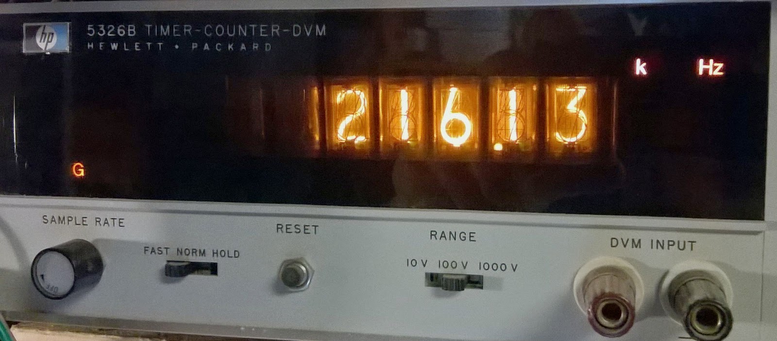
In Norway we have a particular permission for members of the Norwegian Radio Historic Society to transmit up to 500 mW on 216 kHz. I’m not sure if this is output or input power. The permission is meant to cover a collection of historic radios. The frequency is the one used by the main transmitter north of Oslo from 1954-1995 running 200 kW. The frequency is still allocated to Norway, so I guess that is why we may use it this way.
 I grew up close to this transmitter and have fond memories of my first homemade crystal set receiving this station.
There are several low power transmitters around that can be purchased, but most of them only cover the mediumwave band and not longwave (153-279 kHz). Further they are quite complicated as the frequency necessarily has to be user settable.
I looked for a simpler way to make a single-frequency transmitter and found that the function generator chip XR-2206 which I happened to have in my junk box could both generate this frequency and do the amplitude modulation. The RC-oscillator seems to be stable enough for this low frequency although I haven’t tested this much.
Here are the first results with images of the circuit on a Veroboard and the oscilloscope picture of the modulation with my Tandberg TP41 70’s radio on top of it listening to Dire Straits from Spotify streaming over longwave.
 The circuit has very little output power, lacks antenna tuning and harmonic filtering, so there is room for improvement, but at least it works.
Too bad that the XR-2206 is obsolete and not recommended for new development!
 RTL SDR Filters
 |
| SDR Sharp GUI |
DXer John Bellini in Colorado, and maker of those informative Low Noise Vertical videos, has been at it again.
This time it's a good demonstration of a pair of filters that he built to mitigate the front end overload experienced on his SDR receiver.
John is one of many radio hobbyists that have been playing with the very inexpensive RTL 2832 SDR dongle receiver. Being very close to several high-powered broadcast stations has been a bit problematic for him when using the low cost SDR but his new video shows exactly what was needed at his location to solve the problem:
It looks like John is using the SDR Sharp GUI (graphical interface) to operate the dongle SDR receiver. Those wishing to learn more about this might find this 'getting started' page of interest.
Good stuff John.
 Crystals Go To War

Thanks to a recent posting in the Yahoo ParasetBuilders Group, I have a new-found respect for my small collection of prewar crystals! If you've ever wondered how a rough chunk of quartz gets transformed into an accurate frequency-generating device, this 'cinema-style' documentary shows exactly how it was done ... truly an amazingly complex, yet delicate, labor-intensive process.
After viewing the documentary, I can't help but wonder what later health effects some of these workers may have undergone after seeing them handling some nasty-looking chemicals and working directly beside desktop X-ray machines. If you've used old WW2 crystals before, I think you'll enjoy seeing how much work went into their production.
 International Radio Restoration Contest
I have recently been made aware of the Socété Québécoise des Collectionneurs de Radios Ancien's / (SQCRA or Quebec Antique Radio Collectors Society) 'Radio Restoration Contest' and have been enjoying some of the published documents describing various refurburations.
Although the group has been sponsoring the refurb contest for over 10 years, this is only the third year that it has been open to international competition. The rules are interesting and are quoted from the SQCRA website:
A documented report containing photos and explanations and optionally a video of the working set from each contestant must be submitted to us. Then judgement and results are compiled to determine a winner and two runners up.
 |
| courtesy: http://www.sqcra.org/ |

