Posts Tagged ‘homebrew’
 ET Call Home

Late last week I received an interesting e-mail from Thomas Pell in Winter Haven, Florida.
It seems that Tom has been doing some building after reading my series of blogs about my lightwave adventures and has started his own adventure. As he told me initially:
"... I'm retired with too much time on my hands, and I'm tired of the big gritty hobby projects ... after reading about Harvard U's optical SETI project, which looks for extraterrestrial laser signals with a 48 inch, then 72 inch mirror. I thought it would be fun to build a setup like theirs, but at audio frequencies instead of the RF laser signals ... my purpose was to get light signals from other amateur laser dx experimenters or even ET ... better than watching my wife's TV shows. Also a giant telescope that costs almost nothing is fun too."
Tom built up the PIN diode detector shown in my notes, which was a slight variation of the one developed by Roger, G3XBM (see his great lightwave notes here) and based on an earlier plan by K3PGP.
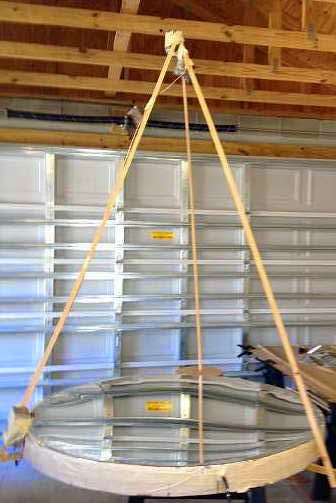
Along with the receiver, Tom built a substantial optical antenna ... a 48" Mylar-based parabolic mirror!
"... it is a wood structure ... round piece of 1/2 inch plywood, 48" in diameter ... around the perimeter a 4" wide strip of 1/8" plywood is wrapped and glued with epoxy putty. On the upper end of 1/8 ply is another circular plywood flange inside. This flange is to glue mylar sheet. The mylar is then tensioned with tape on the side. It is something like a round guitar in appearance... a box ... you suck the air out ... I use a shop vacuum with 1/4 in rubber tube taped to vacuum hose ... hose barb epoxied to hole inside of mirror ... not ideal but if you seal it up well with epoxy, it works..."
 |
| courtesy: Thomas Pell |
It seems that there is now an active movement amongst some SETI enthusiasts to search for optical beacons rather than radio beacons. When you think about it, it would seem to make just as much sense, if not more, to beacon with a modulated optical signal than with a radio signal ... and the optical signal might be far easier to detect. Some of the papers suggest that an optimum frequency would be in the near IR or deep red part of the spectrum, right where most optical amateur two-way work is presently being done.
During his first few tests of the new mirror, Thomas stumbled upon one signal (the only one) which came from just one single point in the sky ... almost directly overhead in Orion.
"At 9:30 pm 3/5/2015, using the amplifier circuit you use in your optical communication receiver connected to a 48 inch parabolic mirror, I received an apparently modulated optical signal originating in center of Orion constellation. Signal was audio frequency low to high pitch and lasted for more than an hour. I located the signal by moving the mirror back and forth across the sky for nearly an hour until I found a "blip", then focused the mirror exactly on the spot to listen to it, incredible experience."
"Received signal again last night from same location. I am becoming convinced it is information of some kind.Very irregular rapidly pulsed. This was only a test of amplifier ... I never expected this result, was totally unprepared. Meanwhile time is passing and I can't seem to contact anyone to have it confirmed before it disappears from the sky. It seems, no one has a setup like this ... this signal is either very important or it's nothing ... I think. Will let you know about outcome."
At this point, Tom is just trying to figure out what type of signal he has been hearing and will be attempting to get a better recording of it over the next few nights. I have heard his initial recording, just done with an I-pad held close to the amplifier's speaker output and it does sound suspiciously like a data train of clicking pulses. Hopefully Tom will solve the mystery soon!
 Phasers On Medium Wave

A recent posting on the Yahoo ndblist Group page, by veteran LF/MW DXer and front-end guru, Steve Ratzlaff (AA7U) in Oregon, described his thoughts on LF/MW antennas and his experience with phasers:
Some years back at the other place, I experimented with phasers, trying
all the various ones I could find or build. I had a long term loan of
the DXE NCC phaser as well. I compared them mostly at MW where a phaser is generally most useful; but also at LF and HF. In all cases and all
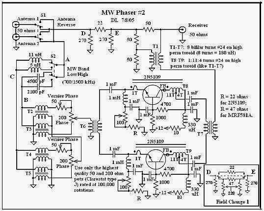
frequencies, without exception, the Dallas Lankford "MW Phaser #2" was
significantly better. I have placed that article in the ndblist Files,
under "Aerials and Technical Files" section should you have an interest
in looking at that article.
For LF use I never found any reason to use a phaser for trying to
optimize the level of a signal. Usually LF signals are short-lived and
often you only have a short time to catch an ident before it fades away.
You can easily waste 30 seconds or more just trying to optimize the
phaser; by that time the signal is usually gone. For those with a local
noise problem from a single general direction a phaser could be useful
in nulling out that noise, though of course you would lose the signals
from that direction too.
I also had room for antenna experiments, being able to compare them with
my longwire antennas. For those with the room, I believe it's hard to
beat an elevated longwire of approx. 400 feet or longer. I was very
fortunate to be able to string two E/W 1600 foot longwires, on either
side of the property about 400 feet apart and roughly parallel; and a
much shorter 400 foot N/S longwire. But even the N/S short one enabled
me to log a number of Greenland beacons (of course this was back when LF
conditions were still excellent, not like now).
Some folks have good results with the K9AY type antenna--Doug in TX has
good results using that antenna. But it's a ground-dependent antenna and
many areas don't have ground characteristics that support such antennas.
My area was one of those--the K9AY never worked very well for me. But an
elevated vertical loop worked very well, using the Wellbrook ALA100
preamp.
I had several rectangular loops up at one time, 120-150 foot
circumference using the ALA100, about 10 vertical feet distance between
the top and bottom wires to give a good capture area. These were very
sensitive at LF and a couple of times I was able to (barely) hear
distant South Pacific beacons that I was also hearing on the 1600 E/W
longwire. And of course the loop antenna is ground-independent so can be
used anywhere. It's bidirectional so can help in nulling noise too. And
such a loop doesn't take up much room as long as you can get it away
from local AC noise (which is true for all LF antennas, especially for
active whips).
Mark Connelly is a prominent east coast MW DXer and has a lot of info on
antennas and phasing on his webpage here. All his applications are primarily for MW DXing but the principles apply equally
well to LF.
The Dallas Lankford phaser article described by Steve, can also be downloaded from here.
LNV phaser, John Bellini in Colorado, also chimed-in with some additional thoughts based upon his own experience:
You do (ideally) need to have good antenna separation to have good/easy phasing of the two signals but you do not have to have two different antennas. If the antennas are too close, the noise fields can be too similar and you won't get good noise cancellation or if the antennas are too close the wavelengths of the signals compared to the antenna separation will be long and it will be a challenge to phase out a signal.
I have been using three, nearly identical, LNV antennas separated 85-110 ft, depending on which pair I use, and have had very good results using the Quantum Phaser.
A very informative discussion of backyard antennas (and phasers) suitable for LW/MWwork is described by Graham Maynard in this Medium Wave Circle article. In the author's own description:
Well, once again I say "That's it". This time my mind churning effort has been to understand and develop the results possible with simple, small back-garden, mixed loop-vertical antenna systems. It really is not as complicated as might first appear, and those willing to try could enjoy as I do, listening to other people's locals ··· Ontario ·· New York ···
These pages have been long in writing - they summarise many years of enquiring study and thoughtful co-ordination with determined and diligent empiric effort...
There's enough good bedtime reading for an evening or two here!
 More Low Noise Vertical Info
MW DXer, John Bellini in Colorado, has recently posted another interesting set of YouTube videos describing the mechanical construction and operation of his cool, and somewhat stealthy, Low Noise Vertical (LNV) as well as his phaser in action against some IBOC and local blowtorch signals.
His use of the phaser is particulary interesting. Here he demonstrates what two LNV's can do when phased correctly. The second antenna being used is one of his wire LNV's located further back in the yard.
The first video shows phasing against local IBOC crud.
The second video shows the phaser in use to knock down the sideband hash from a strong local (KOA) signal, 25 miles away.
For those that like to DX in real time (unlike those using SDR overnight samplings), the phaser has much to offer.
The one being used in the videos is the Quantum Phaser and more information about it may be found here.
More on phasers next time.
 More e-Bay
This week, three items for the workbench arrived...one of them the wrong item, but instead of complaining, I'll keep it.
First off were some 40-pin male pc board breadboard header strips, standard spacing. These will come in handy for making connections to both pc boards or to perfboard. At a cost of ~8 cents per strip and free delivery, hard to beat.
Next were some 2-pin screw terminal block connectors ... nice for a finished-look on a pc board or perfboard power connection. These came in at ~12 cents per connector.
The third item I had ordered was a small pre-built LM317 regulator board as I hate building these and they do come in handy.
However, this was not what I received (a first!). Instead I received a similar-looking AF amplifier board. It is easy to see why they might get easily mixed up by someone quickly throwing orders together for shipping. The AF board was about twice the cost of the $1.43 LM317 board and I can probably use at least one of them in my next lightwave receiver project.
A final item was ordered, from the U.K., some 250 solder lugs for just under 6-cents each, including shipping.
These are becoming very pricey domestically and are even difficult to find at a good price on e-Bay. With the Canadian dollar taking a big hit lately, bargains are even harder to find ... but I think I did OK.
 ’29 MOPA – Small Step
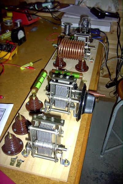
 This morning I completed the wiring of the test-bed MOPA's Hartley oscillator circuit. I was using the 80m tank at the time, wound with 3/16" copper tubing. Oscillator keying is about what I expected ... stable but with some ripple on the note. Even with DC on the filaments, many of these open-breadboard oscillators suffer from RF-modulated notes. Sometime wrapping the power supply or keying leads in a ferrite toroid help or eliminate the slight rasp. On the other hand, some builders prefer to have a note that sounds more '29-like, as in all likelihood, not many notes sounded like pure DC back in the day.
I'm really having second thoughts about my construction method and may just jump to the next (final) construction phase rather than slog through completion of the test-bed model. I've already learned much about the layout by getting to this stage and the extra work involved in completing the test-bed model may not tell me anything new.
I'm using a VT-25 version of the somewhat pricey and hard-to-find type '10' tube. The final version will be built in a similar fashion to my Tri-Tet-Ten, on an aluminum sheet atop the breadboard. Hopefully having the groundplane and shorter leads, will lead to a cleaner note in the final version.
I'm rather dreading this next final phase as there is little room for error. The aluminum sheet must be precisely pre-drilled, as well as the breadboard, and protected at all times (especially when making soldered connections) to prevent any finger marks or scratching on the aluminum sheet. There are still several drilling details to be worked out before I can move forward.
 Measuring The New Lenses

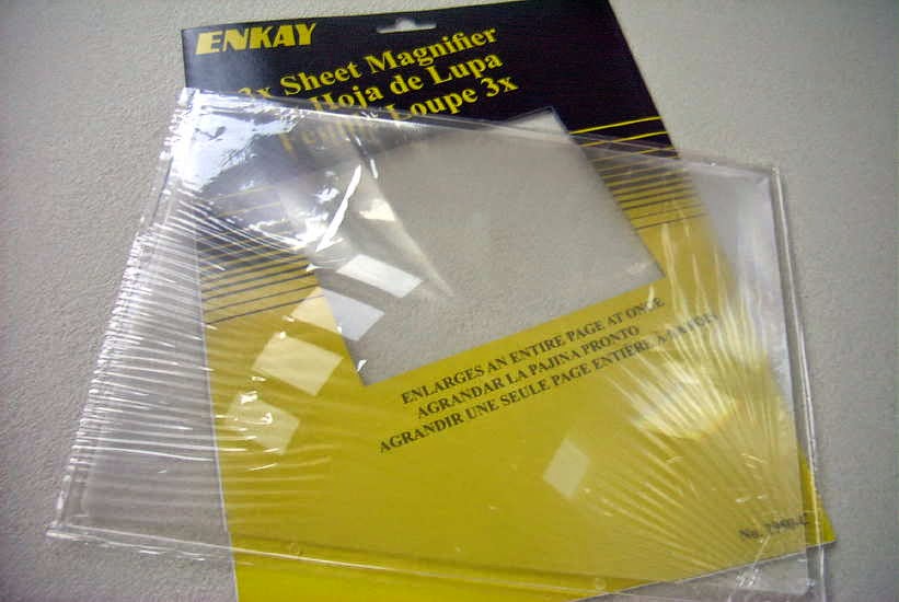
Yesterday I had the chance to have a closer look at the two lenses recently purchased for a new portable lightwave receiver. The initial testing procedure of the page-size fresnel (actual size is 200mm x 270mm) proved incorrect and required more space than the bench top could provide. Eventually the focal length was measured as ~ 368mm +/- for an f/d, or F number, of 1.36 ... a convenient value and much better than the 'other' common fresnel page reader focal length of ~ 600mm. This jibed nicely with the recommendations given in Clint's (KA7OEI) website optical information:
"For practical reasons, it is recommended that an optical system using Fresnel lenses be designed using lenses that have an F-number in the range of 0.5 to 1.5 - that is, around 1. Remember: The "F-number" is the focal length divided by the diameter of the lens, so for an F-number of unity or one, the diameter of the lens would be the same as its focal length."
The lens was able to bring a small LED flashlight (consisting of an array of 21 white LEDs) into surprisingly sharp focus although the shot below does not reflect that due to my camera's poor focus in the darkened room.
The glass 4.5" magnifying lens proved to have a focal point of 203mm for an F number of 1.8. This lense produced an even sharper image of the same light source and may be the best candidate for the portable receiver although the larger aperture of the fresnel might not be worth counting out at this point.
The fresnel may work well for a transmitter and will likely require a small (inexpensive) secondary focusing lens between the LED and the fresnel, in order to have the LED efficiently illuminate the fresnel. The secondary should effectively gather and focus as much of the emitted LED light to just within the boundaries of the fresnel without any wasted light energy being lost to spill-over at the edges.
It would be great to have a permanent lightwave 'beacon' that one could test various receiver lenses and combinations but at present there is very little activity here in VE7 land ... although that is changing, with the interest of another local, VE7IGH (Greg) near Vancouver and right across Georgia Strait from my location. Grant has already built a receiver and will soon start on transmitter construction ... way to go Greg!
 ’29 MOPA / NLOS Lightwave Progress
 |
| Courtesy: http://www.arrl.org/ |
I've now completed a set of tank coils for the new'29 MOPA project. These were wound with 3/16" copper tubing which has become very difficult to source. Luckily, after much searching, I was fortunate enough to find several rolls locally at a very attractive price. Although I do see it quite often on e-bay, sellers either refuse to ship to Canada or their shipping charges are far too high to make it worthwhile. The larger 1/4" rolls are still readily available, but for any given inductance, will take up a lot more room on the breadboard if space is an issue.
These coils cover the amplifier tank, the Hartley oscillator's tank, and the antenna coupling link. Respectively, the coils measure 4.9uH, 4.0uH and 1.9uH.
Winding these is always fun but the method used requires that the needed length be predetermined and cut from the roll beforehand. The first time I did this, when building my TNT transmitter, I learned the hard way to always add at least another foot to cover the additional length eaten-up by turn-spacing and for coil end flattening and mounting.
While visiting Vancouver for a few days I was able to find a couple of pieces needed for my non-line of sight (NLOS) lightwave experiments.
I purchased a nice 4.25" magnifier lens, with suitable focal length, as well as an inexpensive page-size fresnel magnifying lens. What is particularly pleasing is that the fresnel is a rigid lens, about 2 mm thick, unlike most page magnifiers that are thin and floppy. I have yet to test its blur circle or determine its focal length.
I plan to use one or the other of these lenses in a small, portable lightwave receiver module that I can carry to the other side of the island to listen for the main large transmitter, aimed slightly above the horizon, in beacon-mode. If the smaller fresnel does the job, it will be an inexpensive source for anyone else needing a simple lens for either transmitting or receiving.
If the deep-red light tests prove successful, I'll switch the system to IR light but at this stage I'm not sure how focusing and optimizing receivers and transmitters can be done with a light source that is essentially invisible? Perhaps using an IR source that is right on the edge of deep-red will still have enough visible light to allow finding the optimum focus more easily.
More information on NLOS experiments can be found in Yahoo's Optical DX Group as well is in G3XBM' s 481thz blogs.
As well, anyone in the Vancouver lower mainland (as far as the northern Sunshine Coast area) that might be considering lightwave ... I'd love to work you! Pretty well any high spot in this region is direct LOS for me.


