Posts Tagged ‘homebrew’
 ’29 MOPA Progress
 |
| '29 MOPA Plan |
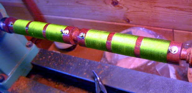
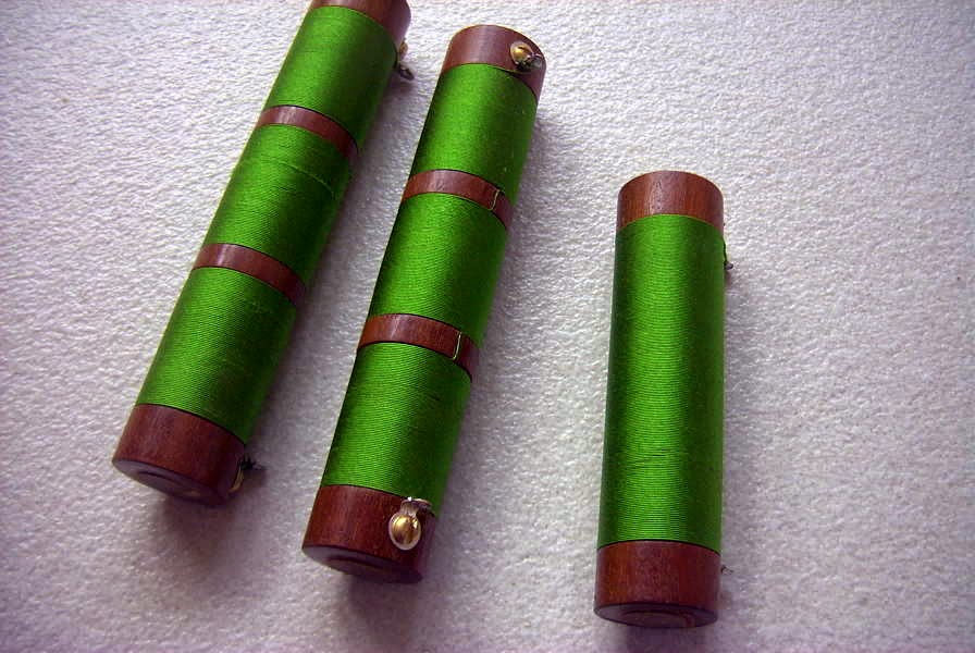
The choke forms were first turned on the wood lathe, using Mahogany hardwood scrap, to a diameter of 3/4", and then stepped down slightly, for the space occupied by the windings. The windings, using single silk enamel #31, were then done, still on the lathe, while rotating the spindle manually.
I've always been surprised at how little inductance is really needed for effective choking on HF and it would seem that the 'standard' 2.5mH is much more than is actually required. The single-ended version is just 190uH, while the three-section chokes measure just 240uH, about 10% of what normally might be specified today.
 The Low Noise Vertical
 There's been a lot of discussion lately on the Yahoo Groups ndblist regarding the "low-noise vertical" (LNV) and it's seemingly excellent performance. Originally described by Dallas Lankford as a good performer from LF to SW, ndblist member, Phil (KO6BB), recently refurbished his earlier built 'LNV', but this time with better feedline and appropriate ferrite cores for the antenna's matching transformers. Some of his description appears below.
To recap. I put the LNV up last spring to overcome the bad IMD products
from local BCB stations I was seeing in the LF region when using the
Roelof Active Whip located about 36 feet AGL. The low noise vertical is
... about 30 feet of antenna, set at roof-line level in this mobile home. As I wasn't sure how well the antenna would perform, I first made it a "Zero Dollar" project, using items I had on hand. Those items included two toroid cores salvaged from a defunct computer PS. I figured that since the supplies operate in the kHz range (as witness what a dirty supply will do to your LF reception), they would be suitable for at least a trial run of the antenna. The balanced feedline was some CAT6 cable I had on hand.
The antenna was a great success, because while it had much lower signal
output than the active whip, it also had ZERO IMD from the BCB stations,
and also less local 'junk' (read noise). The tunable pre-amp I use more
than made up for the lower output of the antenna, after all Signal/Noise
ratio is EVERYTHING in this hobby, NOT how high you can make the "S"
meter read.
The central valley summer heat (often in the 100's) took it's toll on
the CAT6 feedline outer jacket insulation, and while it still seemed to
work OK, I figured that it wouldn't be long before water started to get
into the line and probably degrade it in rainy/foggy weather.
Anyway, I went ahead and ordered the proper toroid coils I needed along
with 25 feet of nice 300 Ohm foam twinlead, and got a couple plastic
boxes to put it all in and made the toroid units. While I was at it ordered
two Amidon FT193-J toroid cores to complete the LNV the way I REALLY wanted to.
Today I installed it all, putting a heavy twist in the feedline to try
to reduce any stray noise pickup on the balanced feedline. I'd say
probably not likely but why take a chance.
OK, here are the results. I took signal level readings of eight 24/7
stations, both before and after changing out the wiring/baluns. The
bottom line is, the new antenna IS an improvement in the NDB range,
tapering off slightly at the high end of the broadcast band. Yeah, it's
'only' a couple "S" units at it's best, but when you're digging for that
weak NDB even 1 "S" unit is a LOT! I'm going to 'assume' 6dB per "S"
unit as I have calibrated the "S" meter of the R-71A receiver.
NOTE: This is 'fuzzy' math, don't take them as 'exact' on the dB readings.
FREQUENCY BEFORE AFTER DIFFERENCE
203 TCY S2 S4 2 S units (12dB)
205 COT S3 S5 2 S units (12dB?)
344 FCH S9+7 S9+15 (8dB)
374 LV S6 S7 1 S unit (6dB)
580 BCB Sta S9+35 S9+38 (3dB)
770 BCB Sta S9+32 S9+32 No Change
880 BCB Sta S9 S9 No Change
1450 BCB S9+10 S9+5 (-5dB)
SO, it looks like the antenna is definitely an improvement where I'm
REALLY interested in it (the NDB band). I could have probably tailored
the toroids for maximum performance, but just used the 81:9 turns ratio
on the outdoors (antenna) and 9:9 on the indoor unit as I'm FAR too lazy
to run up and down the ladder to remove the toroid box, change turns and
retry it again!!!
Some additional notes.
NOTE 1. I have three ground rods dedicated to just this antenna, two 8
footers and a 4 footer. While I was playing with the antenna taking
readings AFTER the work, I disconnected one of the 8 foot rods to see
what effect that had. Signal levels dropped approximately an "S" unit
across the board. So GOOD grounding on this antenna does make a difference!
NOTE 2. I'm NOT exactly sure why it happened, but after the antenna
work here, there was even LESS "local grunge" in the background than
before, even with the stronger signals, making for even better copy on
weak ones than I otherwise expected. . . It DOESN'T make sense to me,
but then, antennas ARE the magic art.
It appears that the grounding plays some importance in the performance of this "non-resonant" aperiodic antenna and the fact that it is non-resonant on the frequencies of interest likely also plays an important part in its good S/N performance.
Several years ago I noticed something similar. My own 10' tuned air-core loop made an excellent receive antenna on 160m, even though the loop was tuned to around 300KHz! Although signal strength was several S-units below my transmitting antenna, the loop was extremely quiet and weak signals were much easier to copy ... In fact I often heard signals on the mis-tuned loop that I could not hear on my resonant half-sloper radiator.
Another ndblist proponent of the low noise vertical is John, in Colorado, who employs three ... one of them a great-looking tilt-over version. The tilt-over is nicely demonstrated in his short you tube video below.
The antennas are also used in combination via his Quantum Phaser, when DXing the broadcast band. The excellent phasing results can also be seen in his short video, while using a wonderful, like new, Hammarlund SP-600 JX.
Dallas Lankford's original article may be found here, while an earlier more encompassing discussion will be found here. A third Lankford article, discussing 'Signal To Man Made Noise Ratios' and comparisons of various receiving antennas, also makes for interesting reading.
Perhaps the 'LNV' might be the antenna you're looking for to boost your LF/MW reception.
 Yet More 630m Activity!
 Another VE7 has been bitten by the 630m bug ... well, intrigued enough to start building a station. On the weekend VA7MM (Mark), in Port Coquitlam, asked if I could take a listen for his low power signal. I'll let Mark describe his setup:
"My transmitter is a HP8640B signal generator. It is stable and has 1 Hz
frequency readout with maximum RF output of 20dBm. CW keying was done by latching the antenna on and off of the HP8640B. The latching relay was driven by the send relay in an IC-746Pro running with full break-in CW
turned on. A 1N914 switching diode was installed across the relay coil as
the back EMF from the relay was measured using my oscilloscope to be a +50V spike. This effectively attenuates the voltage spike. A good safety
precaution before installation.
A second HF radio, an IC-7600, was on a separate wire antenna for receive
only and with Spectran running for signal analysis.
In the final setup three series coils totalling 330 uH and a series of
parallel variable capacitors adjusted to about 1000 pf were installed in a
series resonance circuit outdoors at the base of a sloping dipole with the
apex at about 40 m. The antenna outside shielded and center conductor were connected effectively making the antenna a vertical. There was no impedance matching. One ground radial about 300' long was laid out laying on the surface of the ground. The resonance circuit was tuned using a combination of a Blackberry Z10 smart phone real time video chat link of Spectran from the ham shack in combination with a portable VHF audio feed to both visually and audibly tune the resonance circuit for maximum output. I tried a parallel resonance circuit but it did not work.
The straight line distances between QTHs from Google are:
VA7MM to VE7SL: 60 km
VA7MM to VE7CNF: 10 km
Amazing that a piece of lab equipment can be enabled with a few hours of
tinkering to transmit a signal on the 630 m band a distance of 60 km.
Thanks for the first 630 m band contacts. It was fun. Now I'm going to start planning a permanent capability on 630 m."
Mark's setup reminds me of a Rube Goldberg machine but it all worked well enough for him to put out a solid 559 signal at 60km distance and provide his first official 630m contact.
As of today, the following VE7 stations have now made two-way contacts on the new band:
VE7BDQ
VE7CNF
VE7SL
VA7JX
VA7MM
It would be great to see some activity from northern BC, VE6, VE5 and points further to the east. How about it fellas?
 Lightwave Article From ‘TCA’
 |
| VE7SL Backyard Test |
 A New ‘VE’ on 630m!
 Interest in Canada's newest ham band, 630m, continues to slowly grow. Toby (VE7CNF) in Burnaby, BC, has made his first and second CW contacts on the new band!
 Both myself and John (VE7BDQ) had the pleasure of working Toby on 473.000 CW on Thursday afternoon. Here is Toby's description of his station at present:
"I have put together a low-power 630m WSPR transmitter here. I have a USB-TG44A signal generator clocking a phasing-type SSB modulator with WSPR audio coming from a laptop. The modulator gives 45db suppression of the carrier and lower sideband. This drives a ZHL-32A 1-watt linear amplifier. I have a matching transformer and loading coil at the base of my 80-meter inverted-L antenna. Wire height is 10m.
John VE7BDQ has weakly received my WSPR signal. Are you able to receive WSPR?
The antenna series resistance is much higher than I expected, probably due to 10 year old antenna wire and only 4 ground radials. Right now the antenna match is poor and efficiency is very low. I may rewind the matching transformer tomorrow and gain a few dB. Maybe soon I’ll have enough signal to complete a 2-way CW QSO with you.
I have attached pictures of the hardware. After I determine the proper configuration I’ll make a more efficient loading coil."
 |
| Courtesy: VE7CNF |
 |
| Courtesy: VE7CNF |
 Grow Light Noise?
 |
| Courtesy: http://tomthompson.com/radio/projects.html |
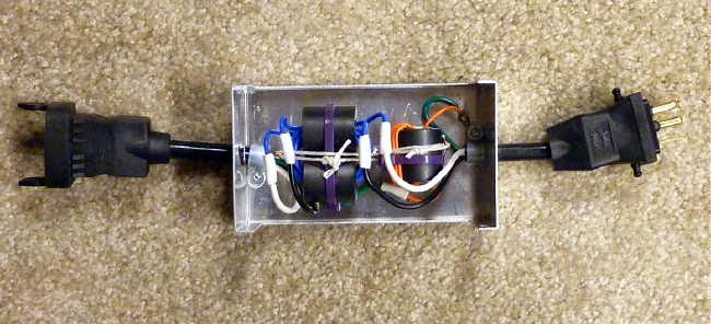
Another type of noise problem was addressed in a posting to the topband reflector today by Don, WD8DSB.....the noise coming from a treadmill's, PWM speed-controlled DC motor.
" For many years my wife's treadmill caused strong interference on 160 meters when it was in use, and yesterday I was able to completely eliminate the RFI using a combination of two different filters (a commercial line filter that provides both common mode and differential mode filtering, and 14
turns of the power cord on a 2.4" OD Fair-Rite #31 mix toroid core based on
the K9YC hams guide to RFI document).
I created a simple website that documents my tests and the filters used,
and for those interested the website URL is:
http://sites.google.com/site/treadmillrfi/
The website contains a link to a video on youtube where you can actually
see the effectiveness of the filters. "
These two amateurs have developed slick solutions to their noise problems, but sadly, noise ingression is rising exponentially it seems and is becoming more and more challenging to mediate.
 VK4EBP’s NLOS Lightwave Experiments – Part 3
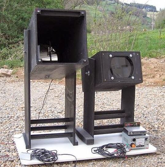 |
| F1AVY's Cloudbounce System |
"Returning to Steve's questions and our general discourse:
..is it (the RX) fairly small and portable...and lensless?
I do have a lens in the RX I now prefer to use - although it happens to be a convex lens from a tabletop magnifier - about 7x12cm giving me a narrow reception beam and a fair bit of gain compared with naked photodiode. There seems to be a general agreement that increasing the size of receiving aperture will capture more light and is the best way to greater gain.
Here I need to qualify gain requirements for my particular applications. I am currently exploring relatively short-distance NLOS paths in urban environments with abundant QRM from city and suburban lights, and this already limits my gain requirements. I developed my own qualitative test of satisfactory sensitivity - by pointing my receiver at individual stars in the sky. If I can hear them twinkle (yes they do twinkle!!!) then I am generally satisfied with the project.
On cloudy nights, pointing the RX into the clouds brings an interesting combination of mains harmonics and general hash from neon lights, clicking pulses from aeroplane lights, sweeping sounds from airport and marine lighthouses. In an environment like this, going to extreme lengths as one would do for very long-range cloudbounce or LOS comms in dark and secluded areas is simply not required and uneconomical. I initially did invest time and money in large receiving boxes with the best components there are, only to find that, unless I moved out into the bush, I could not take a real advantage of the improved performance, and did equally well with smaller and more wieldy portable designs.
"Is the idea, when talking about NLOS, to light up as much sky as possible...and that is why no focusing lenses are employed? Would a focused emitter, as produced by the typical Fresnel lens light box, produce too narrow a beam than desired? It would seem likely that with precise aiming combined with the gain to be had by utilizing fresnels (for example), would produce longer paths??"
There are several separate issues there. One is the implied requirement for a large Fresnel lens in order to obtain a narrow beam. First, how narrow is narrow enough? If we can be satisfied with say +- 5 degrees then there are more wieldy solutions available - most of the high power LEDs now have clip-on small spot lenses awailable separately - usually from third-party manufacturers. These were unheard of until recently. Standard-sized LEDs are available with very narrow radiation pattern, e.g. the SFH4550 at barely +-3 degrees. And one would expect an array of 200+ of them to behave quite like our stacked Yagis, many times over! Hence narrow beam is quite possible even without an external lens.
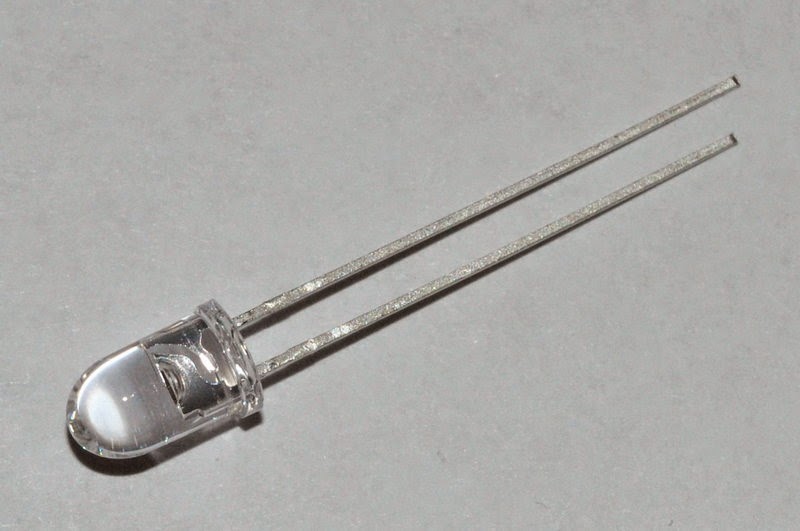 |
| Osram SFH4550 IR LED |
Of course the extremely narrow beams that one would prefer for LOS DX comms would be next to impossible to align in NLOS situation. (Invisible infrared is not a problem in LOS as it can be easily supplemented with e.g. a plain strobe light for alignment purposes.) I find my +-3 degrees array (with similar +-3 deg aperture at receiving end) hard enough to align over the horizon, and it is probably the limit of how narrow one can go to remain practicable in NLOS.
"to light up as much sky as possible..."
It is possible that cloudbounce and obstruction-bounce will develop into separate NLOS techniques, along with atmospheric scatter. Of course one can think of all of these in some topographies.
I had some success in inter-suburban cloudbounce with high beam elevations at both ends - 30 to 60 degrees. Also with 45 degrees or less elevation with TX and RX about 1km apart side by side and pointing at the same cloud in the distance. Power used around 10-20W, beamwidth +-5 to 10 degrees, red and infrared with similar results (including 950nm). The received signal was just strong enough for telegraphy or qrss, but never near enough for any type of voice modulation. Results were affected by the height of cloud cover necessitating frequent elevation adjustment, and an additional liaison channel on VHF. Signals disappeared entirely as soon as the clouds started producing rain.
I never got any usable results with clear night sky and the TX and (imaginary) RX beams crossing each other at similar elevations. Only at very close distances - the best signals being received with blue and infrared. Presumably Rayleigh scatter with blue. (This raises the possibility of usable atmospheric scatter with UV?)
Only recently I commenced preliminary tests with close-to-ground, low-elevation NLOS and immediately the infrared proved itself to be a clear winner with quite reliable and repetitive results. (Needless to say the signal strengths are marginal compared with direct LOS over similar distance.) Intuitively, one would suspect general scatter and bouncing of nearby objects being the main sources of some of the energy reaching over the horizon, with some contribution perhaps of atmospheric/dust/aerosol scatter.
This adds an additional dimension to your question.. to light up as many objects around the TX(or around RX, or around the obstruction) as possible, or send the focused beam as far as possible? I guess it will very much depend on topography. I can imagine a situation where I would prefer to use a broad floodlight rather than a focused beam - e.g. to illuminate as many as possible of the surrounding tall buildings if transmitting from a ground floor apartment. Or from the foot of a mountain. An opposite rule would apply if it is the receiver that is just behind an obstruction - here a focused TX beam and a broad RX aperture might prove advantageous. And where the main obstruction is midway between TX and TX than the usual narrow-beam configuration would apply at both ends. I think it might be worth trying an infrared TX with interchangeable lenses, and same for the RX...
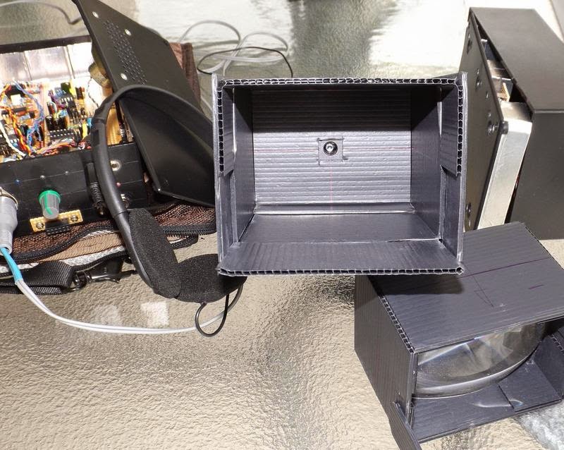
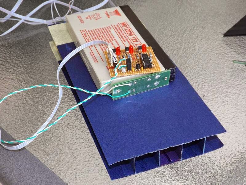
The portable TRX image shows the general view. Most of the electronics is contained in a plastic box and includes an SLA battery, the RX audio bandpass filter, power amp and speaker, and most of the PWM AM TX circuitry except the final LED driver. The DIN socket provides connection to external RX front end TX output drivers and LEDs, usually held together on a tripod. The header socket is for the external microphone connection, and there are switches for power and speaker and a headphone jack. The crudely made corflute box beside it is the RX front end with lens, photodiode and preamp.

The RX detail 01 shows the business end of the photodiode, and the separate lens box (slides in and out for focus adjustment). Detail 02 shows the preamp with interchangeable photodiode modules - SFH213 for visible to 850nm, and the SFH213-FA for 850nm and below.
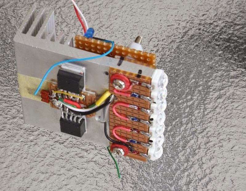
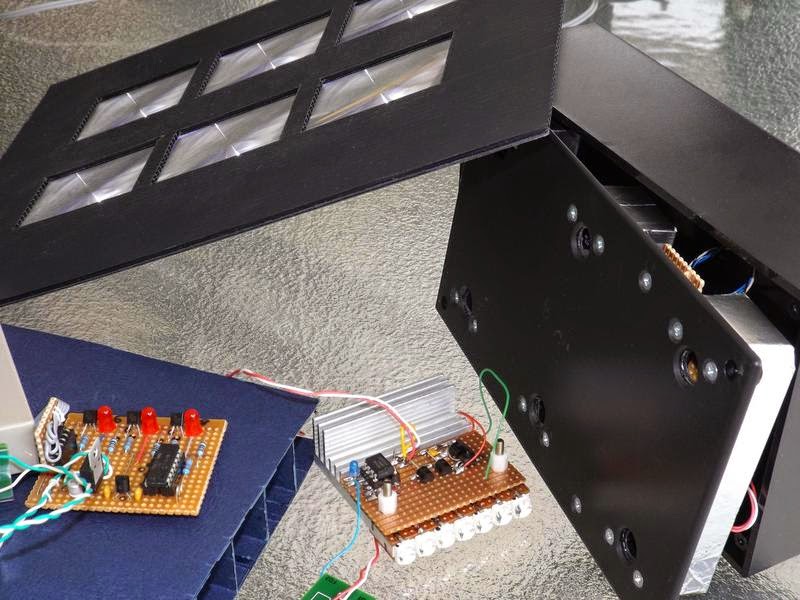
Multi-wavelength TX 01 (front and back image) includes several groups of fat LEDs (red, blue and 850nm) with matching lenses providing approx. +-5 degrees apertures. Also the PWM driver on 2x CAT4101 in parallel, external high current power connection, intensity control, and a PICAXE-controlled strobe or audio callsign/frequency sweep beacon.The whole assembly connects to the TRX control box (above) and can provide power to it, draw power from it, or have both DC sources in parallel.Enclosure includes a photo tripod mount on the bottom plate, and velcro strips on top to hold the RX front end.
Pocket-sized 10W IR TX is a small holiday project and still work in progress. The 7x LEDs are 2W each SFH4783 with an intrinsically narrow beam of +-10 degrees - quite appreciable for a naked LED of this size and possibly obviating the need for external optics in some applications. My usual CAT4101 drivers are included and capable of providing 2A at 50% duty cycle. Another Picaxe beacon is on the other side of the heatsink, and the voice modulator is still in progress.
The low-power multi-wavelength TX is another one day project, built to compare relative performances of 850 and 950nm IR. Three almost identical beams of red, 850 and 950 are transmitted in sequence with approx 100mA PWM running each diode. Unique CW ID has been coded for each wavelength.
6x SFH213 photodiode with individual preamps - quite a respectable low noise, high sensitivity front-end that works very well without external optics (SFH213 have a +-10 deg intrinsic apertures). A matching array of small fresnel lenses has been built and tested for narrow-beam reception, but a permanent box is yet to be added.. Some of the other gadgets seen in the foreground."
As mentioned earlier, Jan's experiments with NLOS signals utilizing IR is of particular interest to myself as I would like to continue experiments with VE7CA, on the other side of Georgia Strait...hopefully with Markus not having to move to a LOS position, but simply aiming across the Strait in a direct path, from his yard. Using Argo and QRSS3 mode, it will be interesting to see if any signals can be recovered from the cloud bottoms on some overnight runs.
More information on NLOS work may be found on the Australian Optical DX Group in Yahoo Groups as well as in the UK Nanowave Group....why is it that these two countries have so much homebrew fun??,,,and don't forget Clint's (KA7OEI) superb Optical Communications / Moduulated Light pages!
