Posts Tagged ‘homebrew’
 VK4EBP’s NLOS Lightwave Experiments – Part 2
 |
| Courtesy: http://www.ledsmagazine.com |
"Visible LEDs and optics: Some of my favourites include the LZ1 and LZ4 series from LedEngin used with matching spot lenses, or thick condenser lenses from old visual projectors. Also various Golden Dragon varieties with matching small plastic spot lenses. Average beam divergence with either configuration is about +-4 degrees. (Happy to provide detailed parts numbers.)
Infrared LEDs: Here we have a some good products from Vishay (TSHG series), with narrow beam (some go down to +-2 degrees) in the standard 5mm packages and max current of 100mA.

They can make nice pencil-beam arrays in combined series/parallel with 200 or more LEDS and no optics required, at less than 40c per LED. Lots of soldering though :). For the 950nm range (not extensively tested yet) the Vishay TSAL range of LEDs will do nicely.
LED drivers: I found a very neat IC to PWM-drive the LEDs at up to 1A - the CAT4101 from ON Semiconductors.
Usually have two in parallel for a peak of 2A at 50% duty cycle, giving me 1A average to drive the LED string.
At the reciving end I am now using a preamp loosely based on Clint's no-feedback design with some hum filtering and other post minor post-processing feeding to an audio amp, or to SpectrumLab."
"...tonight I am trying to compare 830nm against 940nm on a 600m short NLOS path. For this, I have just built a small TX with two "naked" LEDs - TSAL6100 (940nm) and TSHG8200 (830nm). Both have identical shapes of their radiation patterns with +-10 degrees. Each mounted inside of a square cross-section black cardboard tube side by side to ultimately give them a very uniform square beam of approx +-4 degrees. Each driven with 440Hz square wave at 100mA with unique morse identifier for each.
There is a third visible LED as well with its own cardboard collimator and morse ID, to serve as aiming tool and a kind of reference.
The purpose is to see whether 940nm would offer additional advantages in NLOS situations, due perhaps to better/different reflection, scatter, refraction or whatever physical processes might be involved.
An additional advantage might be removing my setup further away from visible light pollution. With the growing popularity of LED lighting in both household and the industry we are having a chance of less and less infrared pollution from traditional incandescent or similar sources - and making light comms more practical in urban environments - all with a simple IR filter at the receiving end.
Tonight's tests were not as productive as anticipated, but somewhat educational nevertheless. First of all the receiving location I picked on the map suffered from severe QRM from sodium street lights. I picked strongly all my "big" IR transmitters, but the visible and the "naked" ones were lost in the QRM, if present at all. I returned home, pointed the 150mW TX into nearby bushland and went for a walk. The red light reception vanished immediately after loosing sight of TX, followed quickly by the 940nm with the 830nm persisting the longest up to perhaps 100m - with the beam fired parallel to ground from upper storey into the crowns of the trees. Reception required pointing the receiver slightly up, intersecting the TX beam somewhere in the tree branches.
Briefly - I confirmed what I already knew: - IR is far superior to visible for NLOS work - indeed visible light is of no use.
- Low elevations and scatter from ground objects is superior to high beam elevations.
A new observation (that I would like to confirm) is that 900+nm is not worth bothering about. It is known that 950nm suffers from greater scatter in atmospheric particles than 850, but this proved to be more of a hindrance than help in NLOS work.
Another practical observation is that the 950nm version of the common SFH213 photodiode (SFH213-FA) works very well in receiving 850nm whilst filtering out lots of the visible pollution (well, perhaps except the sodium lamps!).
I started tonight's session before sunset and got very good NLOS reception of my large IR TXs - in what could be described as quite a bright twilight. (I carry two plug-in front-end modules each with one of the two photodiodes and the input FET.)
Another holiday project - a pocket-sized 10W TX! I found new IR LEDs - SFH4783 - rated at 2W, barely 1.65V of Vf, and intrinsically narrow angle of +-10 degrees. This means no optics, and up to seven of them in series on a small heatsink can be run from a 12V SLA battery.
 |
| Osram SFH4783 |
This reminds me of yet another observation - out of my several large 850nm TXs the best performers are the naked narrow-angle multiple LED arrays - and the one containing 3 high power broad-beam LEDs with spot optics performing the worst. Well the lenses are designed for visible LEDs and I have no guarantee that the material refraction angles and loses are acceptable in the IR range...
Returning to Steve's questions and our general discourse:
..is it (the RX) fairly small and portable...and lensless? (cont'd)...
 VK4EBP’s NLOS Lightwave Experiments – Part 1
A recent posting by Jan, VK4EBP, to the Australian Optical DX Group in Yahoo Groups, has given me renewed hope when it comes to trying some non-line-of-sight (NLOS) lightwave tests. My initial interest in this was spurred by the excellent experimental work undertaken by Roger, G3XBM, all chronicled in great detail in his daily blog postings. A complete chronology of his efforts, filtered for NLOS experiments, may be found by clicking here... but be warned...his information will have you wanting to break out the soldering iron and trying some of these things for yourself or, better yet, with another nearby amateur.
Jan's posting was chalk-full of useful "hands-on" information and was just what I needed to hear and led to some extensive and interesting conversation, well worth passing on to others. I could summarize Jan's work in point form but I think it is more interesting to let Jan describe it himself.
"Finally some success with over-the-horizon light. Briefly - several transmitters of several watts each were fired
simultaneously with the beams aimed at the tops of nearby trees, each
transmitter sending unique combination of tones (direct AM).
 |
| Osram SFH213-FA |
plastic lens approx. 7x12cm. Receiver was aimed towards the TX site and
pointed just over the horizon.
Aural reception of 850nm infrared signals was very good. There was no
trace of TX signals in visible or near-visible spectrum. Signal quality on
850nm was further improved with an infrared-filtered photodiode (SFH213FA, 950nm peak) which provided some attenuation of suburban lights QRM.
My earlier series of experiments over the years was aimed at achieving NLOS short-range communications in a light-polluted metropolitan
environment. I had limited successes with high-elevation cloudbounce over
several km distance using both red and infrared. Very poor results with
high-elevation scatter in clear air, with blue light appearing the best,
and green and yellow the worst for the purpose. More recent tests
suggested that low elevations with infrared light offer a reliable link,
and today's results seem to confirm that.
More to follow! 10km test tomorrow night. 73 de Jan vk4ebp"
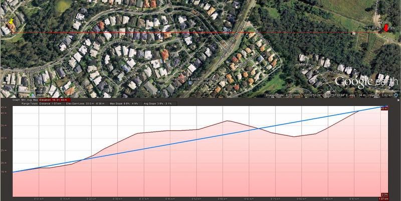
Jan has been testing several different TX emitters / wavelengths, simultaneously, each with a different CW identifier. His path started with a 1km hop through his local residential neighbourhood, with significant obstructions shown below. Later the path was stretched to 10km. His observations involving IR were particularly helpful:
 |
| 1km NLOS Path |
deep red 10W with condenser lens, 3x1W Golden Dragon 850nm IR LED with
+-4deg spot lenses, and 3x 4W LZ1 blue with +-5 deg spot lenses. Manually
switchable by my very patient family members on request via walkie talkie
from the receiving site. The two multi-LED arrays are approx 10W each in
total, one containing a multitude of +-3 deg SFH4550, and the other
+-10deg some other LEDs - do not remember after many years since building it. The small heatsink block contains 4x LZ1 far red, run at about 8W
total."

"At the NLOS location 1km away I was able to copy all the 850nm TXs and
none of the visible/borderline ones.Last night I tried 10km distance.
The topography is theoretically line-of-sight, but isolated from the receiving site by a thick bushland in nearby park. I was firing the transmitters about 3 degrees above what
would be line of sight, thus having about half the beam into the air and
another half scattered in the tree tops near the TX site.
I was able to weakly copy only one of the transmitters - the array of 200 or so of the +-3deg IR LEDs. At the moment I am not certain whether it was from atmospheric or tree scatter.
From earlier tests I observed that IR penetrates very well into the bushland, long after the visible beams were lost both visually and electronically. Similarly, it seems to propagate well into suburban
streets. Presumably the longer wavelength is "seeing" rough surfaces like tree trunks and brick walls as actually shiny and reflecting...."
".... a bit more about my transmitters. (cont'd....)
 The Importance of 1929 – Part 2
 |
| W6BAM - 1929 Compliant. Courtesy : N7RK |
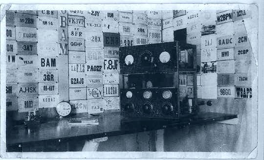
It wasn't long before the ARRL shifted its focus to the new days ahead and seemingly, every issue of QST leading up to the 1929 implementation date, addressed the topic. It is of interest to see how the ARRL interpreted the new rules and developed a strategy to meet the requirements. Many of the rules were broad enough to allow for varied interpretations, all of which could be compliant. In hindsight it seems they made a very good choice on the best way to tackle the present mess on the ham bands...to inform every ham possible of his or her responsibilities for meeting the coming challenge and to show them how.
As far as amateur 'experimental' radio was concerned, the delegates addressed several critical points...in fact, the very recognition of amateur radio itself was a significant step forward for hams worldwide:
"Article 1, {16} the term "private experimental station" means -- (2) a station used by an "amateur," that is, by a duly authorised person interested in radio technique solely with a personal aim and without pecuniary interest."
Although not as big an issue in North America, where governments had long-supported ham radio, for many countries it would mean operational status would now be recognized. The ARRL's campaign to convince hams that their stations must be 'DX-ready' was now given some teeth. Thus began the campaign to convince hams that their 1928 junk must go:
"...for the great average of American amateur stations...it is not a reassuring spectacle in view of next year's requirements. We seriously doubt if as many as one-half of one percent of the active stations to-day are good enough to offer their operators any reasonable chance of success in international work next year. The rest, we think, will have to be rebuilt....floppy waves, bum notes, crawling frequencies, too-big condensers, sloppy practices, haywire assembly, and lack of precision measurements...These must go.. " [QST Editorial, May, 1928]
It sounds alarmingly descriptive of our annual BK Party...but proclaiming that 99.5% of U.S. amateurs would need to rebuild was surely a bold statement and one, as time went on, was gradually toned-down in QST editorials.
Addressing the 'haywire assembly' issue, articles soon appeared showing better construction practices for earlier familiar designs, the self-excited favorites.
| Courtesy: WØVLZ |
Read with caution as you will likely be tempted to begin the parts-search for you own version soon after. It was Niel's superb series of videos that inspired my interest in 1929 construction.
 |
| Hull's 1929 MOPA. Courtesy: http://www.arrl.org/ |
 |
| Hull's High-Powered 1929 Self-Excited Transmitter. Courtesy: http://www.arrl.org/ |
The second article in the issue, "Adapting Medium and High-Powered Self-Excited Transmitters for 1929 Service / Some Design, Constructional and Tuning Considerations Involved", was described by Hull...
"For a week or more, the Laboratory was filled with odors of burning bakelite, hard rubber and wood, and at times whiffs of smoke drifted lazily across the tables -- but in the end our pulse had returned to normal, for we had found that even 250-watt self-excited transmitters can be made to behave in a 1929 manner with just the same treatment we had given the low-powered set".
As noted earlier, it was of interest to see how the men at ARRL interpreted the new rules to such an extent as to call for a complete overhaul of transmitter construction. The Washington delegation had only provided a broad hint as to what must be done regarding stability and spectral purity, while still craftily ensuring that transmitters would always be required to remain "state of the art":
"Article 5, {18} (3) ..the frequency of the waves emitted must be as constant and as free from harmonics as the state of technical development permits"
The ARRL took this opportunity to push the "state of technical development" as it concerned amateur radio. Hull defined the requirements for a 1929 signal as:
"...must be entirely within the limits of the band....its frequency 'flutter' due to irregularities of plate supply must not exceed about 1/30 of 1% (approximately 250 cycles at 40 meters). In addition, the frequency of the signal must be relatively constant. The signal must not 'shimmy' as the antenna vibrates, it should not 'chirp' as it is keyed, nor can it "creep" appreciably as...the tube heats. In short, the frequency of the first dot transmitted should be within 1/10 of 1% (about 750 cycles at 40 meters) of the hundredth dot, even if the plate has reddened...or the voltage drifted. At the end of a few hours of operation the frequency should not have strayed much further." [QST August, 1928]
By today's standards, not a tall order, but in 1928, there was much to be done.
With the deadline fast-approaching, the vigorous campaign to drag hams out of the cesspool of clicks, harmonics, wide signals, raw AC and into the promised land had begun....lead mainly by the hands of George Grammer, Ross Hull, James Lamb, Robert Kruse and Beverly Dudley, nirvana was just over the horizon and surely could be reached .....but only if they rebuilt their 1928 'heaps'. (cont'd)
 BK Bustle
The AWA Builders Group has been buzzing with activity over the past few days as many '29ers get prepared for the upcoming Bruce Kelley QSO Party. If you've been following the blog of late, you'll already know that the BK is the year's premier operating event to celebrate radio as it was in 1929....only self-excited oscillators are allowed (no crystals!) and only tubes that were first introduced in 1929 or earlier. Party activities commence this Saturday afternoon at 2300Z and run for 24 hours....same for the following weekend, only add 160m to the action.
You may hear plenty of activity in the nights leading up to the Party as various stations burn the cobwebs out of their handmade creations around 3550-3570 in the next few nights...you might give them a call if you hear them as most will be delighted to know that they're getting out of their backyard.
A few weeks ago, in the same spirit of preparation, I began work on a small amplifier for my Hull Hartley transmitter. Ever since entering the BK Party, I have been held hostage by the monster winds which always seem to show up here during early December. Self-excited oscillators connected to blowing antennas create an unusual-sounding signal...somewhat musical....up to about 30km, but after that, somewhat dreadful, as shifts in frequency between keying elements can be measured in tens of Hertz or more and make it difficult to copy a weak signal.
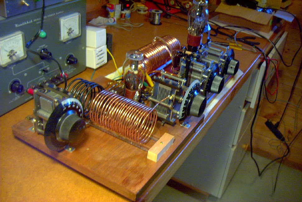
I put the amp together in the original 'ugly construction' style of the 20's, which I'll call 'ugly breadboard'. For the most part, period-appropriate components were used, as it was to be a 'proof-of-concept' project....to see if and how it would work and what changes might need to be implemented in a 'finished' version.
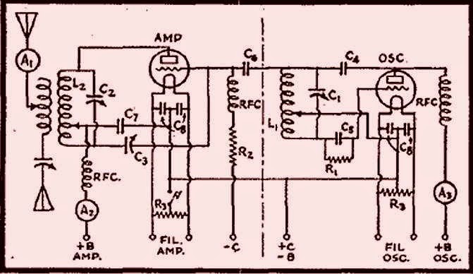
The original circuit, shown below, was published in the February 1931 QST and penned by George Grammer (W1DF), the ARRL's Assistant Technical Editor. Since I already had the oscillator section, I built the amplifier only, making a few modifications.
My changes involved removing the B+ from the exposed plate tank coil by putting C7 between the plate and the tank circuit, grounding the coil tap point and shunt-feeding the B+ directly to the plate. As well, the operating bias was changed from the original combination of grid-leak and external fixed-bias (always a pain) to grid-leak bias only. Since I planned to let the oscillator run and key only the amplifier stage, no external (extra) bias was needed. The original system of feeding drive via capacitive coupling from the oscillator tank circuit was maintained as was the 'plate neutralizing' system. With the plate tank no longer carrying B+, a wide-spaced variable capacitor was no longer required for C3. These changes are illustrated below:
Testing went smoothly and with the help of a tuned RF-sniffing wavemeter (the actual one I built when I was a brand new15 years old ham!), the amplifier neutralized beautifully. It was unconditionally stable, in spite of the numerous clip leads surrounding the board connecting to the separate Hartley oscillator in a somewhat haywire fashion....it really was a mess. As one other '29 builder (KK7UV) so perfectly described his latest workbench project, it "looked like the transmitter was on life-support!"
Surprisingly little drive was required from the Hartley and it was run at just 200VDC. The amplifier efficiency was around 50% which could probably be improved upon with careful attention to biasing values, shorter leads and more efficient antenna coupling. On 80m, the only band that I wound a coil for, keying was clean and very nice (an advantage of being able to run the oscillator at low level). Without too much effort, 15 watts out was easily obtained...far too much for the BK Party.
Tapping down on the tank coil for 40m operation proved to be a different story as the note sounded like a buzz saw...very raspy and nasty. To really undertake a fair test, a dedicated 40m tank coil would have to be used as well as a much 'cleaner build'.
The rat's nest of unwanted coupling of both RF and AC ripple was showing through on this higher frequency.
For multiband operating events, such as the BK, things have to be efficient enough to make band changing and tune-up procedures quick and simple and in its present haywire form, the amplifier would just not be 'contest-friendly'.
All in all it was a very valuable building exercise as a LOT was learned. I am now convinced that for a true MOPA (Master Oscillator Power Amplifier) combination to do what is needed will require an all-in-one style of construction....both oscillator and amplifier on the same board, with short leads and little chance for unwanted parasitic-coupling between stages. With separate coils for all bands and calibrated dials, tuning and changing bands would be very much easier than trying to couple two separate units together. I can see why the struggle to get the original '29ers away from their simple Hartley's and TNT's and over to MOPAS went on for several years.

So once again I am at the mercy of the wind-gods and hoping for two back-to-back Saturdays of quiet BK-friendly air...in early December...on the west coast...by the ocean...yeh, right!
You may hear plenty of activity in the nights leading up to the Party as various stations burn the cobwebs out of their handmade creations around 3550-3570 in the next few nights...you might give them a call if you hear them as most will be delighted to know that they're getting out of their backyard.
A few weeks ago, in the same spirit of preparation, I began work on a small amplifier for my Hull Hartley transmitter. Ever since entering the BK Party, I have been held hostage by the monster winds which always seem to show up here during early December. Self-excited oscillators connected to blowing antennas create an unusual-sounding signal...somewhat musical....up to about 30km, but after that, somewhat dreadful, as shifts in frequency between keying elements can be measured in tens of Hertz or more and make it difficult to copy a weak signal.
I put the amp together in the original 'ugly construction' style of the 20's, which I'll call 'ugly breadboard'. For the most part, period-appropriate components were used, as it was to be a 'proof-of-concept' project....to see if and how it would work and what changes might need to be implemented in a 'finished' version.
 t t |
| Amplifier stage followed by Hull Hartley exciter on far end. |
The original circuit, shown below, was published in the February 1931 QST and penned by George Grammer (W1DF), the ARRL's Assistant Technical Editor. Since I already had the oscillator section, I built the amplifier only, making a few modifications.
 |
| Courtesy: http://www.arrl.org/ |
My changes involved removing the B+ from the exposed plate tank coil by putting C7 between the plate and the tank circuit, grounding the coil tap point and shunt-feeding the B+ directly to the plate. As well, the operating bias was changed from the original combination of grid-leak and external fixed-bias (always a pain) to grid-leak bias only. Since I planned to let the oscillator run and key only the amplifier stage, no external (extra) bias was needed. The original system of feeding drive via capacitive coupling from the oscillator tank circuit was maintained as was the 'plate neutralizing' system. With the plate tank no longer carrying B+, a wide-spaced variable capacitor was no longer required for C3. These changes are illustrated below:
 |
| Courtesy: http://www.arrl.org/ |
Testing went smoothly and with the help of a tuned RF-sniffing wavemeter (the actual one I built when I was a brand new15 years old ham!), the amplifier neutralized beautifully. It was unconditionally stable, in spite of the numerous clip leads surrounding the board connecting to the separate Hartley oscillator in a somewhat haywire fashion....it really was a mess. As one other '29 builder (KK7UV) so perfectly described his latest workbench project, it "looked like the transmitter was on life-support!"
Surprisingly little drive was required from the Hartley and it was run at just 200VDC. The amplifier efficiency was around 50% which could probably be improved upon with careful attention to biasing values, shorter leads and more efficient antenna coupling. On 80m, the only band that I wound a coil for, keying was clean and very nice (an advantage of being able to run the oscillator at low level). Without too much effort, 15 watts out was easily obtained...far too much for the BK Party.
Tapping down on the tank coil for 40m operation proved to be a different story as the note sounded like a buzz saw...very raspy and nasty. To really undertake a fair test, a dedicated 40m tank coil would have to be used as well as a much 'cleaner build'.
The rat's nest of unwanted coupling of both RF and AC ripple was showing through on this higher frequency.
For multiband operating events, such as the BK, things have to be efficient enough to make band changing and tune-up procedures quick and simple and in its present haywire form, the amplifier would just not be 'contest-friendly'.
All in all it was a very valuable building exercise as a LOT was learned. I am now convinced that for a true MOPA (Master Oscillator Power Amplifier) combination to do what is needed will require an all-in-one style of construction....both oscillator and amplifier on the same board, with short leads and little chance for unwanted parasitic-coupling between stages. With separate coils for all bands and calibrated dials, tuning and changing bands would be very much easier than trying to couple two separate units together. I can see why the struggle to get the original '29ers away from their simple Hartley's and TNT's and over to MOPAS went on for several years.

So once again I am at the mercy of the wind-gods and hoping for two back-to-back Saturdays of quiet BK-friendly air...in early December...on the west coast...by the ocean...yeh, right!
 630m Resources – Part 3
Probably the most-often discussed ham radio topic is that of 'antennas' and with LFers it is no different.
When it comes to antennas used for receiving,
you might be surprised to learn that even small, simple antennas, can be very effective on 630m. Small loops are easy to build and work well as they are often quieter than wire antennas and with preampflication, will usually yield a better signal-to-noise ratio.
The shielded Burhan's loop described here, is a good performer on 630m and below, while a tuned wire loop can be just as effective if resonated to 630m.
Easily built active antennas are also popular and once situated in a quiet spot in your backyard, can work extremely well, considering their size and simplicity. The PAØRDT active antenna is popular worldwide and offers good performance, if properly placed, as shown in this LF bandscan from Japan.
Several of the stations that I recently worked on crossband, from 630m to HF, were using their normal HF dipoles to listen on 630m. Often times a non-resonant antenna, such as an 80m dipole, can give reasonably quiet performance and is worth trying should you just want to listen. Others have used HF dipoles with the feedline shorted and fed as a top-loaded vertical (T), and resonated to 630m against a small radial ground. Try what you presently have and you may be surprised at what you can hear.
Transmitting antennas need not be large to enjoy 630m propagation. For most backyards, an inverted 'L' antenna would probably be the easiest to configure.
If you have a tower, the vertical portion of the 'L' could be hung from a support arm off of the tower, with the horizontal portion as long and as high as possible. If you have some trees to hang wires from, a center-fed 'T' antenna would also be effective.
 |
| Top-loaded 'T' Antennas. Courtesy: http://en.wikipedia.org/wiki/T-Antenna |
In both of these examples, try and get as much 'vertical' as possible and then work on the top-hat portion. Top-hats with multiple wires will also increase antenna efficiency. An interesting paper by VK2DX, explains the process that he used to build and match a simple inverted 'L'.
 | |
| Courtesy: VK2DX |
As well, JUMA publishes an informative application note on building an 'L' for 630m.
If you don't have room for one of these types of antennas, effective results can also be had with short top-loaded radiators as used at many NDB installations. Try to go as high as you can and make the top-hat as large as possible.
Any of the transmitting antennas described above will require sufficient series inductance (base loading usually) to bring them to resonance as well as some form of variometer to fine-tune exactly. As well, they all require some form of ground system to radiate.
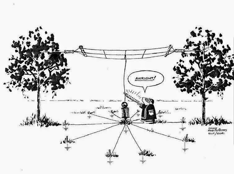
Since most backyards will never be large enough for an efficient ground system on 160m, let alone on 630m, just do the best that you can. You might be surprised at the results achieved with just a simple system of a few buried radials but the more you can lay down, the better. Radials can be effectively hidden beneath the grass with a few days of effort. Some have noted an increase in antenna current when ground rods were driven in at the far end of the radials.
 |
| Courtesy: http://www.auroralchorus.com/ |
This well-written series of articles describing simple antenna systems for the 1750m band is chalk-full of neat ideas and practical information...all applicable to the 630m band.
For an even more in-depth look at practical LF and MF antennas, the ON7YD site is hard to beat...again, all applicable to 630m.
Canada's new 630m band is a wonderful opportunity to build and experiment with all aspects of your station and it's crying out for activity!
It's still not too late to be the first station on 630m from most parts of Canada and the VE7's are waiting to work you!
 FTDI still bricking chips?
I doubt anyone missed the recent FTDI driver controversy.
The Scottish company Future Technology Devices International (FTDI) released an updated version of their USB-to-Serial driver for Windows on their website late September and last month the driver became available via Microsoft Windows Update. It soon became apparent that these new drivers could 'soft brick' counterfeit and software-compatible clones of their chips by re-writing the USB product ID (PID) to "0000". This action prevents the chip from being recognised by drivers of any operating system, effectively making them inoperable unless the PID is changed back. This clumsy and ill thought out measure was intended to protect its intellectual property.
The ability to reprogram the USB Vendor/Product IDs is a feature of FTDI devices offered to equipment manufacturers and so most bricked devices could be reset by using the downloadable FTDI utility.
Obviously there was much outrage from the hobbyist community and FTDI were roundly criticised and as a result the malicious driver was supposedly removed from the Windows update system.
Or so I thought...
I am currently constructing another data mode interface for some experiments with FreeDV. It requires the usual PTT control driven using the RTS line from a serial port. I purchased a couple of simple TTL level interface boards on eBay which claimed to use FTDI chips.
I built up a little scrappy veroboard circuit with an open-collector drive transistor and plugged into the shack PC and everything seemed okay as this PC already had an older FTDI driver installed.
I am using another computer for the FreeDV experiments and plugged the board into this thinking it too already had a safe FTDI driver installed but instead it brought up the installing driver dialogue and appeared to go online and download drivers and install them. I really didn't pay much notice as I wasn't too worried as any malicious drivers had supposedly been pulled and sure enough after installation everything appeared to work, the port appeared in device manager.
I unplugged the board to make a slight change and was surprised when I plugged it back in the PC the driver installation dialogue reappeared followed by an error message saying driver couldn't be installed and contact the manufacturer.
The serial port now appeared in the device manager with a yellow exclamation mark saying no driver installed error 28. Examining the device details showed that the VID was still 0403 but the PID was 0000 it had been bricked! Unfortunately not soft bricked as I have been unable to reset the chips PID using the FTDI utility.
I am not exactly sure what has happened but still a case of beware when it comes to FTDI devices and I shall be avoiding them from now on.
 630m Resources – Part 2

Using the transverter approach offers the advantage of providing a higher-stability signal generated by the main station's transceiver oscillator system. Most of the digital modes require a higher stability than would be needed for straight CW.
If your main interest is normal speed CW, then a digital VFO, such as the one devised by GW3UEP, would do the job.
If you are content operating on 475.0 kHz, then an inexpensive 7.6MHz crystal, in a divided-down oscillator will work well, and with good enough stability for some QRSS work as my earlier "GW3UEP Transmitter In QRSS Mode" report indicated.
The other option for frequency generation is a DDS.
 |
| N3ZI DDS |
For those wanting something a bit more robust, W1VD describes a very nice high-power transmitter. His website is packed with useful circuits and ideas for both 2200m and 630m.
 |
| W1VD Dual-Band Kilowatt : http://www.w1vd.com/ |
W7IUV also describes, in great detail, his method of generating high-power on 630m. There is much to be learned from his document describing the design and operation of his unique 'linear-mode' transmitter.
 |
| W7IUV 630m TX: http://www.w7iuv.com |
Another practical way of generating moderate power, certainly enough to meet the Canadian 5W EIRP limit, is to combine two or more 100W transmitters, such as the GW3UEP transmitter. It is reasonably simple and inexpensive to combine several modules with the use of a homebrew power combiner, as previously described.
 |
| Homebrew 630m two-Port Power Combiner / VE7SL |


