Posts Tagged ‘homebrew’
 ’29 Style Transmitters…What To Build? – Part 2
When it comes to putting a transmitter together for the BK, there are a lot of choices! My advice for a first-build '29 rig would be either a simple TNT or a Hartley-style oscillator. Both are easy to get operating and, when correctly optimized, are capable of putting out a nice-sounding signal.
For a first-time build, with the main objective being to have something ready in time for the December BK, I would not be concerned about overall appearance or period-appropriate parts. For now, the only thing that must be period-appropriate is the tube...improvements can come later.
As well, I would not be overly-concerned about running the maximum power of 10W input. If you are able to get a type '10' or the equivalent VT-25, or a pair of 45's, then the legal-limit is easily within reach. Utilizing something smaller, at just a few watts output, should not be considered a deterrent, as BK-operators all seem to have very good ears. Just 2 or 3 watts will guarantee plenty of contacts no matter where you are located!
Shown above is a fine little TNT built by Kevin, WB2QMY, in New York. It uses a very affordable UX-201A triode, originally manufactured in 1925 for radio receivers. Although Kevin's TNT puts out barely 2 watts on 80m CW, we had no trouble working each other in a recent BK QSO Party. If you build it, they will come!
If you prefer to tackle a TNT, here is the information you will need. This circuit appeared for several years in the ARRL Handbook's transmitter-section. I suspect that it was probably built by thousands of young hams in the late 20's and early 30's and affordably introduced most of them to the magic of radio. For more building details, including how to keep high-voltage off of the main tank coil, see the information on my website describing the TNT project.
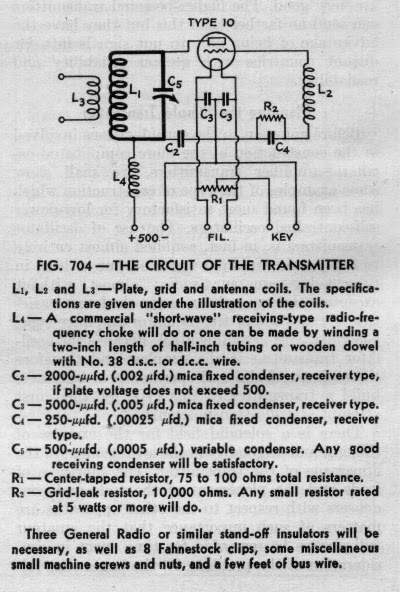
Should you be interested in tackling a Hartley, here is an interesting circuit described by Nick, WA5BDU.
 |
| Courtesy: WA5BDU |
Such a transmitter would readily lend itself to a parallel arrangement of two or more triodes, such as the 27 or the 45 and would develop good power levels inexpensively.
ABØCW has designed a Hartley oscillator using a pair of 27's in parallel and uses them to drive a small amplifier. As described on his website, the oscillator would make a fine stand-alone transmitter with a simple link-coupling antenna circuit.
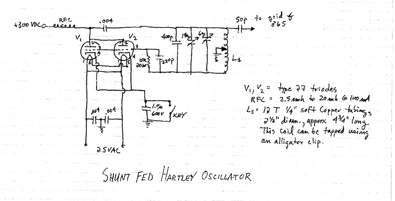 |
| Courtesy: ABØCW |
You can find a list of '29-style related building links, as well as a gallery of transmitters constructed by others, at the bottom of my TNT web page here.
And....circuit ideas, help with parts and lots of BK-chat can always be found at the Yahoo AWAGroup where the focus is mainly on building and operating.
 ’29 Style Transmitters…What To Build? – Part 1
 Most hams in the late 20's and early 30's seemed to be using simple transmitters...one or two tubes at the most. No doubt the poor economics of the time made it difficult to build anything really elaborate but it didn't seem to stop them from getting on the air with whatever they could put together.
New rules for amateur radio signal stability came into effect in 1929, making that a pivotal year for amateurs, resulting in several new ideas for 'modern' transmitters hitting the publications of the day.
All of the simpler, one-tube transmitters, were self-excited oscillators capable of pretty good sounding signals when operated correctly and when the wind wasn't blowing the antenna around. Being directly-coupled to the antenna meant that any variations in antenna impedance caused by antenna wire movements, would result in the note rising or falling in frequency by several hertz with the resultant 'musical-sounding' note. You can usually hear lots of these during the windy winter BK Party!
From what I can determine, the most popular first-time transmitter was the one-tube TNT (Tuned-Not-Tuned) style as it could usually be built with parts stripped from an old broadcast receiver.
With a low parts-count, it was easy on the pocketbook. The grid coil was broadly resonant near the plate circuits frequency, resulting in enough feedback to sustain oscillation. The grid coil really needs to be optimised (a simple procedure) for peak efficiency and note quality. You can listen to the note quality on my own TNT while transmitting on 40m.
The Hartley oscillator is just as easy on the pocketbook as the TNT, and in the opinion of most, capable of an even better-sounding note once properly optimized.
This transmitter is optimized for best note-quality and plate efficiency by finding the correct tap point on L1. Hear my own Hartley's tone while transmitting on 160m.
The third common transmitter of the early 30's was the TPTG (Tuned-Plate-Tuned-Grid).
The TPTG style is a step-up from the TNT and similar in design. Although the added expense of a second variable capacitor made it less popular than the previous two styles, optimizing performance was somewhat easier since the grid circuit could be more readily adjusted for the oscillator's 'sweet-spot' without having to add or remove turns on the grid coil.
All of the triodes mentioned in my previous blog will work well in the above circuits. Keying is normally accomplished as shown below, by connecting the balanced filament resistor on the directly-heated cathode to ground.
It is important to know that construction need not be fancy to get on-the-air for the BK and there is no reason why modern components cannot be used, along with the era-appropriate tube. If you're still undecided, I'll give you some building details to consider next.
 Building …. ’29 – Style
As mentioned in an earlier blog, the annual winter Bruce Kelley (BK) QSO Party, usually spurs some new construction of transmitters styled after those that were popular in the late 20's and early 30's. The main stipulation for entry into the two-weekend affair is that transmitters must be self-excited (no crystals) and use tubes that were available in 1929 or earlier.
Initially this might seem a difficult task, and that was my first reaction when first learning of the vintage operating event. Once I had learned more about these types of transmitters and actually listened to the BK action, I knew that it was something that I really wanted to do. After seeing several inspiring videos from Neil (WØVLZ) and Joe (N2OUV), demonstrating their homebuilt '29 TNT transmitters, I knew it was something that I really had to do! Perhaps the videos will grab you as well:
One of the first things that might seem impossible to obtain would be a suitable tube that was available in 1929. Most of the tubes used in transmitters back then were designed for receivers, usually audio tubes that were pressed into RF oscillator or amplifier service. In the dirty-thirties, larger RF tubes were expensive and beyond the reach of most amateurs unless they had deep-pockets.
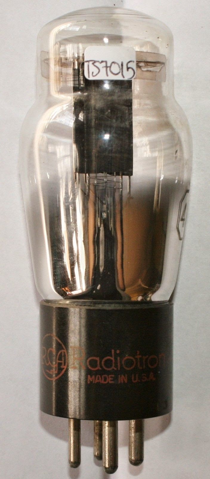
Tubes commonly found in BK transmitters are the type 10, 210, 45, 245, 27 and the 227. All of these types are still available today with some being more costly than others.
 The most common tube is the type 10 or 210 which is also available in a military format, still NIB, as the VT-25. This is the same tube used in the WØVLZ transmitter.
This tube can easily handle the 10W power requirements imposed by the BK and then some.
Typical prices range from $50 and up.
The next most popular is the 45 or 245, which is pretty well maxed-out at around 5-7 watts. The cost of a 45 is about half that of a VT-25.
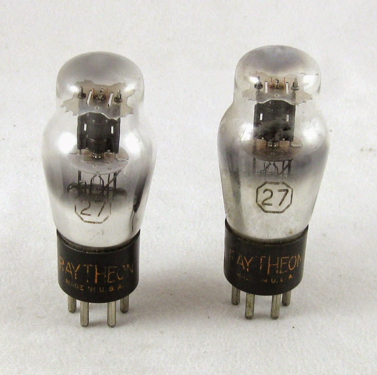
The widely available and inexpensive 27 / 227 will produce 2-3 watts of output...more than enough to work across the continent under normal conditions. The low cost (around $5) makes these particularly attractive for the first-time builder as a transmitter using a pair of these (or more) in parallel is an easy way to get started.
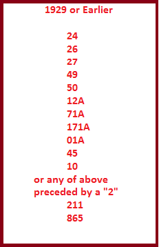
Here is a list of popular tubes that could be used for BK-eligible '29-style transmitters. There are probably more but these are the ones seen most often:
Suitable tubes are always available on e-Bay and from dedicated online tube-sellers. A quick Google-search will turn up several sellers, with prices and condition. Of course, one of the first places to look should be any of your ham friends with deep junk-boxes, especially those that have been building or amassing parts for many years. Check out the next ham fleamarket...especially those dusty old boxes under the seller's table. And...there are probably several hundreds of basements still filled with suitable old parts, just waiting to be liberated....seeking them out is all part of the '29 building fun.
Once a decision has been made to go forward with a '29 project, the first thing is to decide on the type of transmitter to build. There were three popular designs back in the late 20's, each with their own pro's and con's. I'll tell you more about these next and give you a few suggestions for getting started.
In the meantime, see what your 'oldest' ham acquaintance might have in his basement and keep an eye-out for any ARRL Handbooks from the early 30's as they are full of valuable building ideas....and you may wish to check-out K7JPD's ideas for finding old parts.
 VE7BPO Homebuilder Web Files
The recent closure of Todd's valuable site has resulted in the entire data from there now being mirrored at two locations in .pdf format. It's all there, complete with all the schematics and photographs from the original site ...and is very easily searched. The file is about 40Mb and consists of 945 pages!
- Jason, NT7S has posted the file here.
- Steve, VK2JA has posted the file here.
If you missed it earlier, Todd's new blog is slowly starting to take shape and by the looks of it will soon be running full-speed ahead.
 VE7BPO ‘Popcorn’ QRP / Home Builder
“The emphasis is fun. The hope is that it will attract new people to electronic design, measurement and experimentation. Hopefully, this site stimulates interest in QRP homebrew electronics.”
That's how Todd Gale, VE7BPO, described his website. Up until this past weekend, Todd site was one of the Web's premier sources of inspiration, accumulated homebrew knowledge and hands-on experimental wisdom. I was shocked to receive an e-mail from Todd explaining that the site would be taken down because of continued bandwidth / network struggles with his one and only choice of providers. It truly was sad news for myself and the thousands that regularly visit his site for guidance. However, all is not lost as Todd went on to say:
"....I will convert all the site files into pdf files and stick them on a download site sometime in the future. I may re-emerge with a small-scale site or blog at some point, but don't really know for sure."
Happily, today Todd has informed me that he will indeed begin a new POPCORN QRP blog in which he hopes to update with his benchwork descriptions that we have all come to enjoy.
I have listed Todd's blog site on My Blog List to the right but you may prefer to set your bookmarks for his site. Don't expect too much until later in the month as he is still working his way up the blogger's learning curve....hopefully we will see him back soon. Best of luck with your new endeavour...and, like the original website, I'm sure it will be great!
 |
| Courtesy: VE7BPO |
 New LF / MF Loop
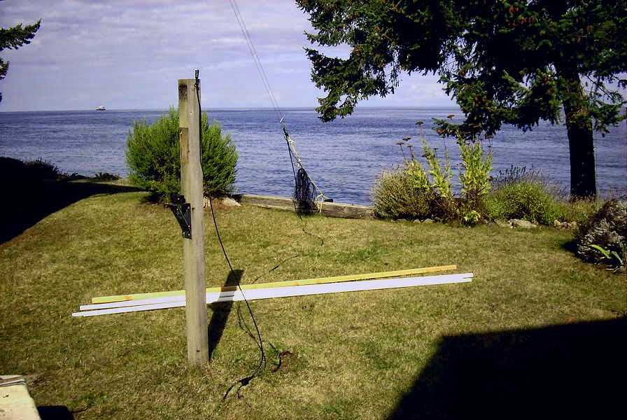
Some may recall my blog back in July (Wellbrook Loop Plans) describing a new loop that I had been thinking about as a possible replacement for my 10' shielded loop. I had been doodling various construction ideas using PVC tubing in an effort to keep it as light as possible, without introducing any metal near the loop. On Monday of this week, I dismantled the 10' loop in preparation for my new experimental rectangular loop.
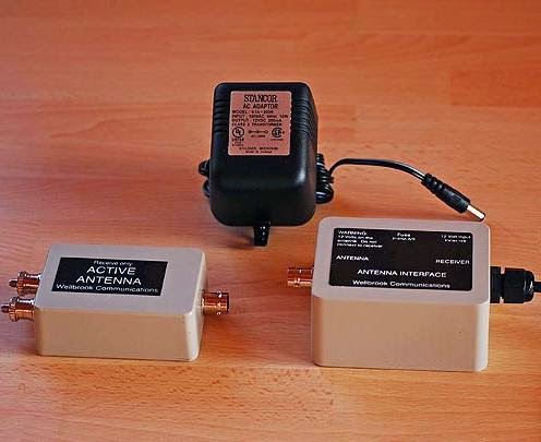 I've had the Wellbrook loop preamp here for a few months, so it was now or never, while the weather was still 'antenna-friendly'. Now I do understand that this goes against one of ham radio's long-standing traditions that dictates all antenna work must wait until the weather can't get any worse. Antennas built in the winter rain always work much better than ones put up in the summer. Hopefully it's not Wouff-Hong or Rettysnitch punishable but the fall DX season is almost upon us and I'm not waiting for the rain!
The new 'loop' is not really loop-shaped but is rectangular (10' x 20') and more like a Flag antenna shape. I considered a Flag but really don't need any back-end nulling capability since I'm mainly interested in listening to the east and to the north.
The main boom section is composed of two sections of 1" PVC thick-wall (Schedule 40) pipe joined at the center and reinforced with a 10' section of 2" x 2" Douglas Fir. In addition, the boom has a truss of 1/4" Dacron to take out any end-loading sag. The vertical end sections are 3/4" Schedule 40 PVC pipe, fastened with a T at the boom end. The center mast is made of 2" Schedule 40 ABS pipe with a long section of 1 1/2" ABS nested inside that telescopes upward to anchor the truss ropes and give some additional rigidity to the mast.
 |
| Main boom and mast construction |
 |
| Looping E/W |
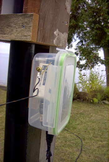
Although the preamp is completely sealed and weatherproofed, I still decided to mount it inside a container. The container also provided a convenient anchor to terminate the loop end wires (PVC-coated #18 stranded) without putting any tension on the soldered terminals.
Although I have not had much time to listen, and conditions are still in 'recovery' mode from earlier disturbances, initial indications are that everything is performing as well, if not better, than expected. It certainly outperforms my 10' active shielded loop by a large margin. I have yet to do any serious S/N comparisons between it and my primary LF receive antenna, a large inverted L, which must be tuned to resonance for the desired listening range. I believe that the very quiet loop / Wellbrook combination will provide an overall S/N improvement.
I have always believed that smaller loops provide deeper and sharper front-to-side nulls so I was pleasantly surprised to measure (using Perseus) null depths from 25-30db, on various groundwave signals....more than expected. Skywave signals also deliver sharp deep nulls in the order of 22 - 25db...again surprising, but I'll take them! A brief listen pointing S-E last evening turned up good signals from 1 kw'ers KYHN (1650kHz) in Fort Smith, Arkansas and KKGM (1630kHz) in Fort Worth, Texas. An early morning listen revealed good audio from JOIK (567) Sapporo, Japan and JOAK (595kHz) in Shobu. Down in the ndb band, little 25-watter 'IP' on 210kHz was an all-time new catch from Mobile, Arizona.
There is still much to learn from this new antenna system but the biggest challenge will be keeping it up all winter. I did lose one of my 10' loops after several years, due to wind when the main (un-reinforced) PVC mast eventually failed from flexing fatigue. I will tie the ends of the new antenna down when the winds get strong to reduce as much mast flexing as possible. I could however, run the risk of violating another long-standing radio tradition..."if your antenna stayed up all winter, it wasn't big enough". I just can't win.
 Building For The ‘BK’
 It's almost that time of the year when, once again, the '29ers start preparing for the winter Bruce Kelley Party. In case you're not familiar with the 'BK', it's a winter event celebrating the transmitters of 1929 and earlier. Transmitters used for the event must be self-excited only...no crystals allowed...and the tube(s) used must be those that were available in 1929 or earlier. It's an eye-opener to hear how the band must have sounded in the early days of amateur radio CW...even better if you're making those sounds yourself. The 'BK' usually spawns a flurry of construction, so if you think it is something that might interest you, you have until early December to get ready! Unfortunately many aspiring 29ers always leave it too late and inevitably run out of time before all of the building challenges can be overcome.
Over the next few weeks I'll have more to say about the 'BK' and '29 style in general, since this year, I hope to add an amplifier to my self excited Hull Hartley, shown above.
For now, I'll tease you with the basic information regarding the QSO Party as published by the 'BK' sponsor...the "Antique Wireless Association"......just in case you want to start planning an entry (hopefully!).
The Bruce Kelly 1929 QSO Party is a yearly AWA sponsored event where participants build their own transmitters using the designs, techniques, and tubes that were available in 1929 and earlier, and then put those classic transmitters on the air and try to contact as many other 1929 stations as possible. Since they use early designs, it is a cacophony of whooping, chirping, buzzing, clicking, drifting, swishing, swaying, warbling, and other interesting signals. This is what ham radio sounded like in 1929 and for two weekends in December its 1929 again on the ham bands.
This year for the first time we are activating Bruce Kelley’s W2ICE call sign as a 1929 SPECIAL EVENT STATION! W2ICE hasn’t been heard on the 1929 QSO Party since Bruce’s passing so this will be a real treat to hear and work the namesake station of this event! A special event QSL card will be available for valid contacts with W2ICE. QSL information will be posted on the AWA website. W2ICE is operating as a 1929 station and contacts count just like any other station. The 1929 QSO Party was started in the early 1990’s and championed for many years by Bruce Kelly W2ICE, an AWA co-founder. Prior to Bruce’s passing, he asked his close friend John Rollins W1FPZ to keep the 29 QSO Party going. John Rollins managed the QSO party for many years and renamed it the Bruce Kelly 1929 QSO Party in honor of Bruce. Ten years ago John Rollins asked me to manage the 29 QSO Party for him and Bruce, and to keep the event alive because it meant so much to both of them.
Dates: Sat. Dec. 6, 2014 @ 2300 GMT to Sun. Dec. 7, 2014 @ 2300 GMT and Sat. Dec. 13, 2014 @ 2300 GMT to Sun. Dec. 14, 2014 @ 2300 GMT
Objective: Contact as many 1929 stations as possible. Contact exchange consists of RST, Name, QTH (State such as ME or MN or NY), last two digits of the year of the transmitters design or publication (such as 29 or 27 or 23), type of transmitter (such as TNT or TGTP or MOPA or COLPITTS), and power input (such as 6W or 9W).
Rules: Transmitters must be 1929 or earlier types of self oscillators such as the Hartley, TNT, PP tuned grid tuned plate, MOPA, Colpitts, etc. No crystal oscillators. Tubes must have been available during or before 1929. Typical tubes often used are type 10, 45, 27, 211, 71A. Individual stations can be worked only once on each band over the course of two weekends. You can use any vintage or modern receiver that you wish. The event is open to all 1929 stations including non-AWA members and AWA members. You are encouraged to join the AWA and support 1929 radio!
Input Power: Transmitters are limited to a power INPUT of 10 watts or less. However, to help make East-West contacts, power may be increased to 20 watts INPUT between the hours of 0500Z (12 Midnight EST) and 1300Z (8 AM EST). Note this is INPUT power. Power input is calculated by multiplying PA plate voltage x total PA plate current. Example: my plate voltage is 300 volts dc, and plate current is 30 ma, so total input power is 300 x 0.030 = 9 watts input. Stations running more power than this are considered “modern” for this event and do not count.
Frequencies: The QSO Party typically operates between 1800 to 1810 Kcs, 3550 to 3580 Kcs , 7100 to 7125 Kcs, plus or minus depending on QRM. 40 meter activity is up significantly because it offers both night time AND daytime propagation! So when 80 shuts down Sunday morning, I hope to see you on 40m. (Courtesy AWA)
Presently, almost all of the activity is from Minnesota and points eastward....the west is poorly represented for some reason but activity out this way has been slowly increasing over the past two years.
You don't need much in the way of power....every year I work several eastern 'BK' stations that are running just 2 or 3 watts, usually using receiving tubes pressed into RF oscillator service....much like the real boys of '29 likely did.
If you want to try something really different and relive the days of early amateur radio then you've still got time to get started. I have some helpful building hints on my VE7SL Radio Notebook site.


