Posts Tagged ‘homebrew’
 A New 630m Loading Coil & Variometer
I've decided, for the time being, to keep my 2200m (136kHz) antenna tuning system separate from the 630m system. This means that I'll need to build a new loading coil, variometer and impedance matching transformer. I'm not really sure why I should maintain the 2200m capability since there is not really much activity here. The only two excuses that I have at present are the fact that it took a heck of a lot of work to get to this point (but it was mostly "fun work") and that the U.S. may be getting the band soon. I'm also not convinced that even if the U.S. does get the band that it would translate into much new activity....so, for the time being, I will keep the system intact.
I've used an online coil calculator to design the coils needed for loading and for the variometer....it will be interesting to see how close the finished values compare with the calculated values. I hope they're not too far off! Here is what the plan calls for:
The main loading coil will be built on a low-loss 6" styrene pipe coupler using #16 solid copper transformer wire, spaced at 3mm. The coil will be elevated above the main form by strips of styrene rod that I have filed small notches into, every 3mm. The rod height will be staggered around the form, gradually stepping down one full turn every 360 degrees. Inside the main coil, the smaller variometer coil will be wound with poly-covered #18 stranded wire on a short length 3 1/2" PVC pipe.
Hopefully I'll get something that tunes from 130-230uH, approximately....if so, I'll not only be happy, but really surprised!
 Smoke Testing The GW3UEP 630m Transmitter
 |
| Drain (top) vs Gate (lower) on testbed Class-E GW3UEP TX |
I've just completed the Muppet-styled printed circuit version of my previously breadboarded GW3UEP 630m transmitter. The earlier version was built "ugly style" in order to optimize part values and measure circuit parameters.
 |
| Testbed (Ugly-Style) |
 |
| Final Version (Muppet-Style) |
Running the TX at 12.8VDC on the drain(s) at 2.3A produces an input power of 29W. The measured power out, after the LPF, is 23W into a 50 ohm load. This represents an efficiency of 80%. When run in the normal speed CW mode, the FETs run cool enough that they would probably not even need a heatsink but if run in any of the QRSS (long keydown periods) modes, would certainly benefit from heatsinking.
Running the TX at a higher voltage of 22.6VDC (on the amplifier only) yields a current of 4A for an input of 90W. Measured output power is 71W for an efficiency of 79%.
Heatsinking would be required at this power level, even for normal speed CW but the finals seem to run just slightly warm. A larger heatsink or possibly a small fan as well would be required for any QRSS CW modes.
I suspect that the efficiency could be further improved yet with very fine tweaking of the output circuit L/C network but the extra few watts gained would not be significant.
At either power level, this easy-to-build transmitter would make a great "first 630m transmitter" for anyone wanting to get started on our new band.
 Tuggle-Style LF Regens
 If the name sounds familiar, you may recognize it from reading about the DX crystal radios that Mike Tuggle has created over the past several years. Some might even say that his state-of-the-art and very elegant "Lyonodyne 17" crystal radio re-kindled the modern day interest in crystal radio DXing, once the mainstay of all radio adventures.
 |
| Mike Tuggle's Lyonodyne 17 Crystal DX Tuner |
The challenge was too hard to resist for many and the contest was popular for several years running. Some of the inventive entries for individual years may be seen here. The contest logbooks also make for interesting reading and demonstrate the capability of some of these simple radios.
Although the contest has not been run for the past few years, there is still much interest and discussion of "1AD" radios on Dave Schmarder's "RadioBoard" forum.
Mike's LF tuner is a prime example as he uses it daily and continues to post some amazing DX to the Yahoo "ndblist" Group. His furthest ndb catch in North America with the regen has been "YY" in Mont Joli, Quebec.
Now, "YY" is a good catch for me, from B.C., but Mike is listening from Kaneohe, Hawaii !
You can read about Mike's original design here, while his latest version shown below, incorporates a dedicated LF antenna tuner.
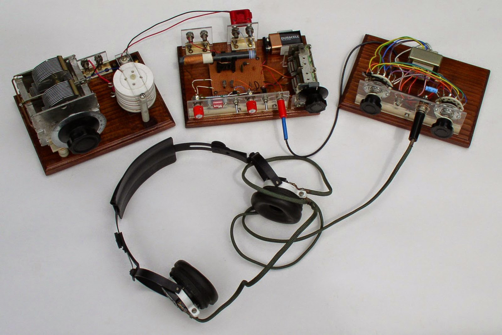 |
| LF Regen (Courtesy Mike Tuggle) |
 |
| LF Regen Schematic (courtesy Mike Tuggle) |
 |
| Courtesy: Roelof Bakker, PAØRDT |
Roelof has also published a nice write-up describing the project which sparked a lot of "must build" discussion within the group.....even enough to make Mike get out his soldering iron and build the European-version!
As old and as simple as they are, regenerative receivers still hold much fascination amongst radio builders and dollar-for-dollar are amazingly good performers, especially on LF.
 So you want to play with a Pixie?
 |
| My own surface mount version of the Pixie2 |
This page provides a guide to Pixie and related kits in a table format. These are simplistic single-band transceivers which are fun to build, yet they perform well enough to be used, although with some effort, for real contacts.
The idea of using the power amplifier transistor as a mixer seems to come from George Burt – GM3OXX – whose five transistor FOXX was described in 1983 in SPRAT. The basic design of the oscillator, PA/mixer and the simple keying has been more or less unchanged since RV3GM – Oleg Borodin – described the four transistor Micro-80 in 1992 in SPRAT. Later the Pixie 2 by WA6BOY replaced two of those transistors with the LM386 audio amplifier (QRPp 1995). Most later versions are variants of these designs.
Foxx | |
 Foxx-3 kit from Kanga, £29.95 | Incorporates a sidetone oscillator, changeover relay and low-pass filter. Different versions for the 80, 40, 30 or 20 m bands |
Micro-80 | |
 Kit from QRPme, $35.00 | Micro80D. Updated version with choice of high or low impedance headphone, polyvaricon tuning cap and board mounted connectors, 80 m. |
Pixie2 | |
 Kit from HSC Electronic Supply, $14.95 | For 80 and 40 m. Eham review |
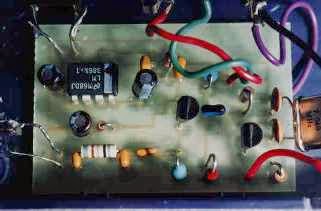 Kit from Kenneke, $29.95 | Includes 80 m crystal |
 Kit from QRPme, $40.00 | Lil Squall Transceiver ][. Several components and the output low pass filter are on sockets. Comes with a crystal for 40 m. |
 Ali Express Ham QRP DIY Kit Shack 40 m, $15.07 | 40 m version. Tuning pot for VXO. |
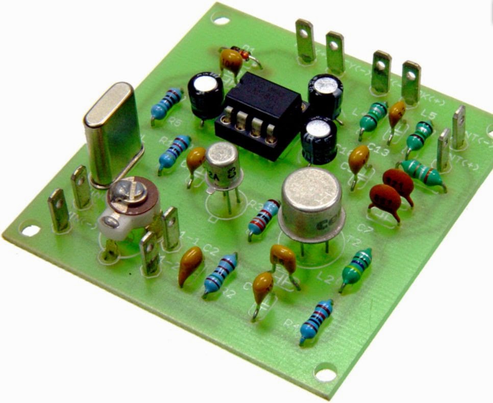 Radi0kit, £22.00 | Enhanced Pixie2 which comes in 80, 40 and 20 m versions. Judging from the PCB layout it has an improved pin 7 muting circuit. |
What can we say to characterize these designs? One the one hand they are very simple to build and get to work. One the other hand they are also simple in the sense that they do not always perform very well. Therefore I don’t think I would recommend them to any novice ham. It takes some understanding of frequency offsets and sidebands in order to make real contacts. But many have had great fun with this minimalist transceiver which in its basic version puts out some 2-300 mW. And it encourages experimentation and modifications. Also, it should be remembered that it isn’t really necessary to get a kit, as the Pixie 2 is quite simple to build from scratch also. I did that myself.
The original designs and many variants and modifications are documented in the Pixie file document of SPRAT. There are many, many more clever modifications out there and I have my share on this blog also. To sort out and link to all the other pages is too daunting a task, so therefore I have focused on kits here. Finally I wouldn’t be surprised if the table is incomplete so I would appreciate comments if you think that something is missing.
 630m Trans-Pacific WSPR
 |
| Courtesy: https://www.google.com/maps/ |
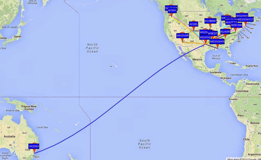
This is particularly noteworthy in view of the relatively low power used for John's beacon....around 200W. With the typical backyard antennas being used at these frequencies, efficiencies are very low and John's actual ERP is less than 5W. The transpacific reception of John's signal by VK2DDI confirms what most LF'ers already know....that small suburban lot amateur installations can have positive results on 630m without the need for huge antenna systems.
The WG2XIQ beacon was operating in the WSPR mode, which has become very popular amongst 630m experimenters as well as those just interested in listening-in. WSPR is not a QSO mode but strictly a one-way 'beacon' mode. Although two stations may each spot each other, it is not considered to be a valid two-way QSO. A check of evening WSPR activity will often reveal dozens of stations actively spotting what they are hearing.
Like most LF stations, John's is mostly homebrew.
| WG2XIQ/KB5NJD |
I'll let him describe the details:
"I have a few ways of making RF in the shack. I can do CW with a very nice waveform using the GW3UEP VFO/Driver coupled with a GW3UEP 100w amp with waveform shaping. The other way is via the MF Solutions transmit downconverter, developed by John Molnar, WA3ETD/WG2XKA. I have two of those boards, one is a backup. I use a GPSDO for the LO and use that signal to drive two parallel GW3UEP amps with max power at 125 watts each. The W1VD Ø degree hybrid combiner brings them together in phase for close to somewhere between 200 and 250 watts TPO depending on how hard I drive and how close I match the TX levels entering the combiner. I filter the output with the W1VD KW LPF that was built by Dave Robinson G4FRE (ex WW2R). I power the amps with a pair of BK Precision 30V 6Amp variable power supplies (variable current limit threshold also). Scope match is used to resonate and match the the impedance. IF Rig on 630m is typically a Yaesu FT920. These days RX antennas are the VE7SL multiturn loop or the TX vertical, both of which have their own merits depending on the conditions at the time."
| John's 630m Vertical |
"Antenna is an 80 foot asymmetric T-top marconi with 100 foot and 200 foot legs....radial system is almost 3 miles of radials connected via various busses. 26 ground rods around the property. I monitor current in the shack and sample via a Bauer current transformer from an AM BC ATU."
| 630m Radial System |
John's system does indeed work well...just last year at this time, his 630m signals were copied by KL7L near Anchorage, Alaska.
Of course, equal credit must be given to VK2DDI for having a system good enough to hear John's signal all the way down on Berry Mountain, New South Wales, Australia! It is there that David has set up a fine LF station, 500m above and overlooking the Tasman Sea...an ideal location for weak-signal LF work.
 | ||||
| VK2DDI - Berry Mountain, NSW |
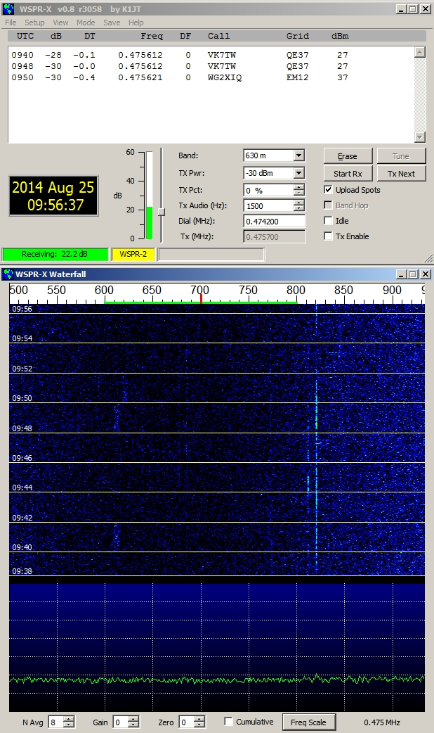 | ||
| WG2XIQ Signal As Heard in VK |
David also runs the Berry Mountain Grabber, providing other VK and ZL experimenters a handy way of checking their system progress or propagation conditions.
If you have been doing any WSPR work on HF, you might be surprised at what you can hear down on 630m, even without a dedicated antenna for that band. Surprisingly good results can often be had with a non-resonant antenna as the signal to noise ratio can often be better even though signals may sound weaker. Give it a try and spot what you hear!
If you are interested in learning how to receive WSPR, here is a nice tutorial by ZS6SGM.
Should you be interested in knowing more about obtaining a Part 5 licence to transmit on 630m, John will happily guide you through the process. He can be contacted via email or you can find him hanging-out most nights on the ON4KST kHz (2000-630m) chat page.
To keep on top of what is happening or who is on-the-air, most LF'ers rely on three sources:
- the RSGB LF Group reflector
- the Lowfer list
- the LWCA Message Board
 On Making Nanowaves – Part 6
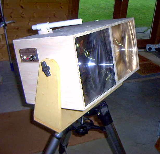
After the transmitter and the receiver had been accurately focused (the receiver's photodiode at the fresnel's focal point and the transmitter's secondary lens properly positioned) both enclosures were screwed together and mounted on a tripod.

Markus, VE7CA, had checked-out a suitable location not far from his home QTH on the road to one of the local ski-hills. This gave him an unobstructed view to my location on Mayne Island, about 54km to the southwest. I had planned to set up in my front yard, about 15' above sea level and on the eastern shoreline with a direct shot to Markus.
Even though we were using LEDs rather than lasers, I still felt somewhat uneasy as our path crossed directly over the runways at Vancouver International (around the path midpoint) as well as the main ferry lane between Vancouver Island and the B.C. mainland. Considering the distances involved, I probably need not have worried as the light, although bright, would cause no physical harm other than possible momentary distraction or curiosity. If one of the ferries had been approaching the path, I had planned to shut down until it had passed as it would have been hard to convince authorities that the light really was not a laser, before they carted me away!
After waiting for the usual winter B.C. rain to subside, we finally had a promising evening shaping up, although somewhat cold. Markus, accompanied by Jim, VE7BKX, loaded his vehicle and headed for the mountains. With neither of us having 2m portable radios, we somewhat guiltily reverted to cellphones to announce setting-up status.
 |
| VE7CA/7 |
Almost immediately I heard his beacon signal although there was no visible sign of his light.
Before final alignment I made a quick recording of his signal.
Neither if us had any real idea of what type of signal strength to expect and we were both very surprised to hear how strong the signals were. Once we had both aligned and our lights were now visible, we switched to CW mode and proceeded to work each other in typical QSO mode.
Hear is a recording of Markus sending my RST report.
Signal reports as well as grid squares were exchanged just to make everything 'official'. We then settled into a nice twenty-minute ragchew until the cold winter air took its toll on our fingers forcing us both to close down and pack up for the night.
Markus grabbed a short cellphone video from his end which shows the still fairly bright twilight skies and the LED signal source:
Earlier, John (VE7BDQ) had made the decision to not build a transmitter as he preferred not to go portable. Both of us were interested in pursuing a possible non-line-of-sight (NLOS) path by using either 'cloudbounce' or 'clear-air scattering' which would allow John to set up in his backyard. The path between us is much shorter than the VE7CA/7 path as can be seen in the map below:
 |
| Courtesy: https://maps.google.ca/ |
For one-way beaconing, I plan to add a more accurate crystal-controlled tone module so that my CW signal's frequency is precisely known and can be watched for in the very narrow bandwidth window of Argo or Spectran over a given period of time. Even at these slower speeds, QSOs exchanging the minimum required information can still be made relatively quickly. Hopefully any reception at all of my signal at John's location will excite him into building a transmitter as well. Completing a two-way contact using the NLOS mode would be a very interesting challenge.
In the meantime, Markus and I have been seeking out possible new locations for his remote work, using "HeyWhat'sThat Path Profiler" web site. This site quickly indicates the distance and headings between any two points and draws a geographic contour of the path showing any obstructions.
 |
| Courtesy: http://www.heywhatsthat.com/profiler.html |
Markus hopes to get out to one such favourable location in the Fraser Valley mountains, before the weather turns nasty once again.
If there is anyone in the Vancouver lower mainland region that might be interested in building a lightwave station to join us in the fun, please do not hesitate to make contact with any of us...we would love to hear from you!
If you are a member of the Radio Amateur's of Canada (RAC) and receive their 'TCA' journal, please watch for our upcoming article in September's issue..."A West Coast Lightwave Project".
 On Making Nanowaves – Part 5

The next step was to use John's design to mount the receiver and transmitter modules so they could be locked into position once aligned properly. His system used the 1/4" split shaft locking mechanism removed from an old Allen-Bradley potentiometer to hold a short length of rod fastened to the module's case.

This allowed the shaft to be moved forward and backward for focus while the slot in the mounting plate allowed for vertical centering. The plate mounting mechanism itself allowed for lateral centering. This system allowed for the locking of the receiver's photodiode at the exact focal point of the fresnel lens.The same scheme was employed for the transmitter's LED as well, since accurate focusing was critical there also.
In order to focus as much of the LED's light onto the primary fresnel lens, a small inexpensive (secondary) collimating lens was required. This assured that the fresnel was properly illuminated out to its edges and no further. Any light spilling over the edges of the fresnel would just be wasted.
Our particular fresnel had an effective aperture of 260mm and a focal length of 200mm, producing an F-number (f/D ratio) of .76.... Clint suggested that our collimating lens should have an F-number of ~ 1 - 1.2 and be a PMN (Positive MeNiscus) type and that we hedge our bets by trying lenses above and below that value. Ideally the collimator should be at least 25mm in diameter for ease of mounting and, when perfectly illuminating the fresnel, be as close to the LED as possible, if not touching it. Just placing a less than ideal secondary too close to the LED would end up over-illuminating the fresnel, while having it too far away would under-illuminate it.
Accordingly, four small glass collimating lens of various F-numbers were purchased from Surplus Shed at around $4 each. Each lens was then mounted on a drilled-out piece of PCB material using 'JB Weld'.
Once cleaned-up, the lens board was then positioned directly over the center of the LED on a machine-screw carriage mount. The carriage allowed the lens to be locked into position once it was correctly positioned. All four lenses were tested to see which one would correctly illuminate the fresnel while still being as close to the LED as possible.

The eventual winning secondary lens was #L10016 (.9 f/D) which allowed for a sharp and fully-illuminated fresnel while being just a few millimeters above the LED.
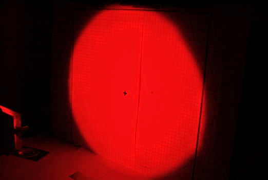
The next step was to adjust the entire LED and secondary carriage for the sharpest focus on a distant flat surface. This was done over a distance of about 200' and was a fairly fine adjustment.
Once done, it was actually possible to see the two fine wires connecting to the LED die on the distant projected image.
With the final focusing taken care of, the tone modulator and MOSFET LED driver were installed. This used an IRF540 switching FET, driven by the digital tone signal to control the current through the LED.
All we could do now was patiently wait for a nice clear evening to put the system to work.


