Posts Tagged ‘homebrew’
 The advantage of the single-lever paddle
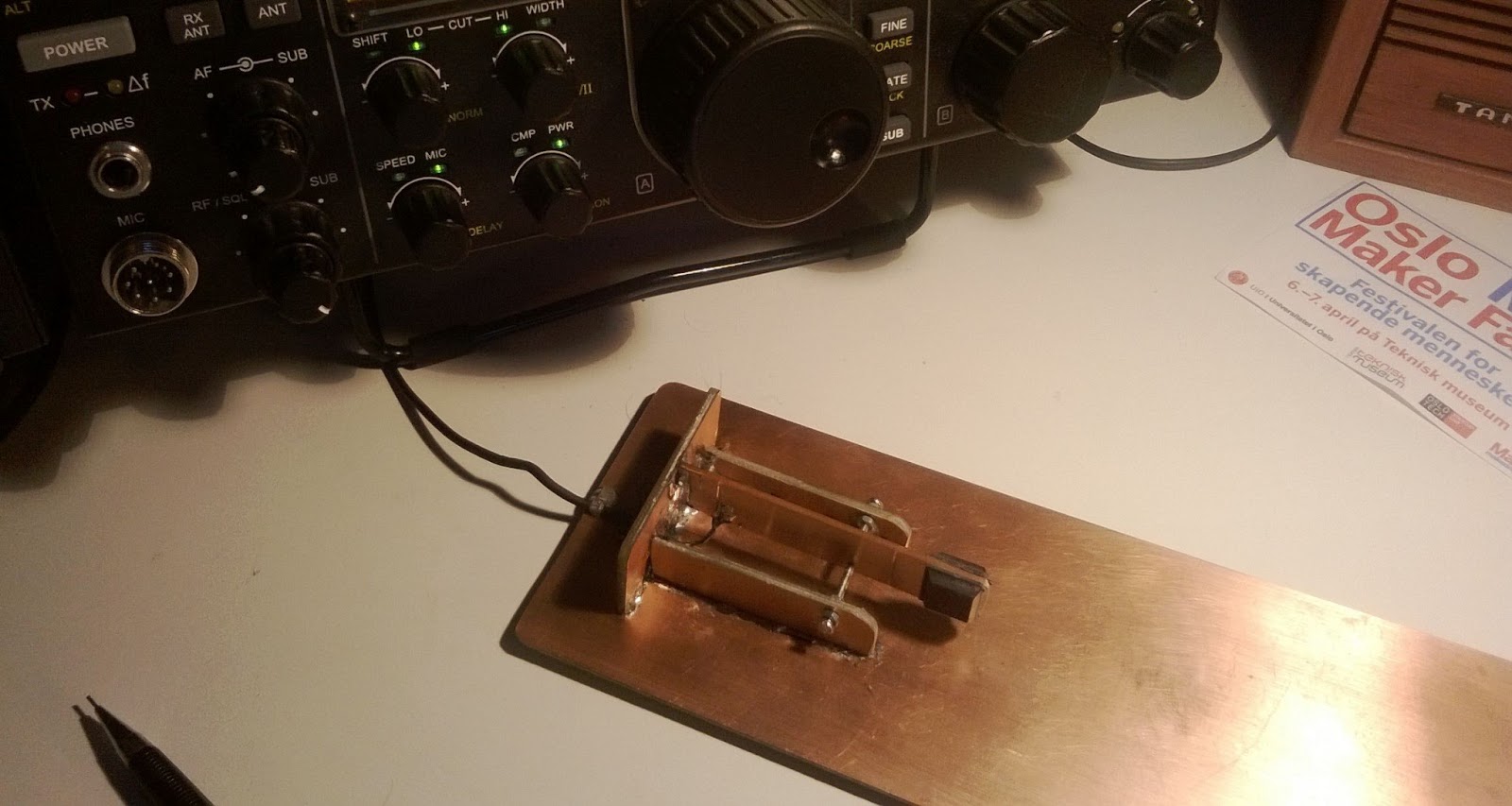 |
| My single-lever PCB keyer KI6SN/NB6M-style |
It may seem like a bad idea to downgrade from a dual-lever paddle and iambic keyer to a single-lever paddle. It must be inefficient since each individual dash and dot has to be generated by a right or left movement of the paddle. Despite this, many of the champions in the High Speed Telegraphy competitions use single-lever paddles, often home-made ones. How can that be?
K7QO, Chuck Adams, wrote “Using an Iambic Paddle” and compared the dual-lever paddle with the single-lever with respect to number of movements. If all 26 letters of the English alphabet and the numbers from 0 to 9 are sent, the single-lever paddle requires 73 strokes while a dual-lever and an iambic keyer requires 65. This is 11% less.
But when N1FN, Marshall G. Emm, wrote “Iambic Keying – Debunking the Myth” he analyzed the 7 letters that are faster to send with an iambic keyer – C, F, K, L, Y, Q, and R – and found that only one of them, the L, is among the 12 most frequent ones in English. He illustrated it this way:
Guess what’t wrong with this figure? He didn’t see the R and forgot that it is also among the most frequent letters!

So two of the faster letters are among the most frequent ones, not just one. I guess that N1FN’s estimate of only a 5% increase in efficiency when letter frequencies are taken into account is a bit too small then. In addition comes the fact that CQ, and all Q-codes use letters that are more efficient with the iambic keyer, so in radio amateur use the efficiency advantage of the iambic keyer is probably even more than 11%.
So this doesn’t explain the fact that many of the high speed champions do so well on single-lever paddles. My experience is based on learning to send Morse code at the age of 47. Somehow I feel that this was 20-30 years too late in order to master all the finer movements involved in iambic keying.
The issue must be tolerance to errors, not just efficiency. The high-speed champions value that and increasingly the producers of morse paddles are including single-lever paddles in their assortment.
A single-lever paddle is also easy to make yourself, much easier than a dual-lever paddle. I made one from printed circuit board based on the paddles of KI6SN. That design was a modified version of the miniature single-lever paddle of NB6M. I made it just to try the concept before I move on and eventually buy one. But the homemade one was surprisingly good to use, so I might stay with it for a while. The nice thing is that the single-lever couldn’t care less if your keyer is set up for iambic A og B. Neither if the keyer does the ultimatic mode which I promoted recently (Is the ultimatic Morse keyer really that efficient?)
There should be freedom in choice of paddle, so everyone should find what suits best regardless of what is the current fashion or what it is that is considered to be ‘best’. So whether you are a newcomer who struggle with learning to send properly with an iambic keyer, or an oldtimer who keep using the dual-lever as if it is a single-lever paddle, feel free to change to a single-lever paddle. I am sure you will notice a reduced error rate.
The question for me is what “real” single-lever key I should upgrade to, they all look attractive: Begali, Bencher, Bushwhacker, Hi-Mound, Kent, K8RA, N3ZN, Scheunemann, UR5CDX, Vibroplex, …
Cobwebb success
After what seems like a lifetime in the attic the Cobwebb ventured outside for the Easter weekend. What a weekend as well.
I put the little antenna up on the telescopic pole about the same height and the top of the Hustler 6-btv (in the background) and spent a few minutes tuning into various stations then dashing in and out of the house to swap the feeder over between the two antennas. Several dashes later and the freezing cold east wind finally kept me in doors just as 2 VK stations appeared on the cluster. At the time I was on the vertical and paid little attention to them as experience tells me that they wouldn’t be ‘in range’ with my 100w. Especially as I was at home in the st bees dip which usually strips rf out of the ether. I tuned to their operating frequency and was met with stoney silence, as expected.
Out of curiosity I did one last switch and the first station was a real 5 & 9. A few calls later and we managed my first qso with a vk. A few minutes later I bagged my second. Within a few hours I managed 7 new countries in between walking the dog and other family stuff. I can safely say that I will be making a more rugged version of the single wire Cobwebb and retiring the vertical.
Now the bands have returned to their usual quieter state it was certainly a good weekend to be on the radio

1 Volt/2 Volt Transceivers
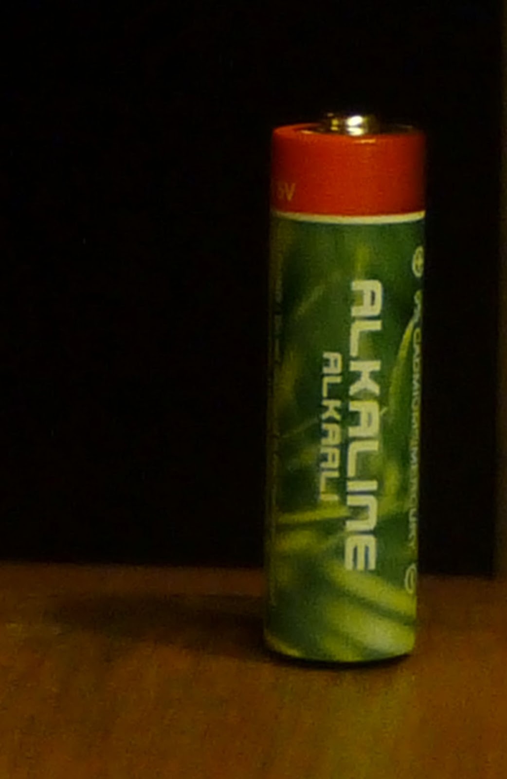
Transceivers with a power supply of 1 and 2 Volts, how much can one achieve with that? Well, actually quite a lot according to DL2AVH, Helmut, who together with DL4ALJ, Gero, wrote two articles about that in the German QRP-Report in 2011. I am impressed by the output power, up to 200 mW with one battery cell (1.5 Volts) and 0.5 Watts with two cells.
I wrote about this in April last year where I also mentioned that the 1 Volt design from 2000 later had been corrected. Those corrections can be found in the article in QRP-Report 3/2011: “Niederspannungs-Schaltungtechnik – der 1-V- und der 2-V-transceiver” (Low voltage circuit technology – the 1 Volt and the 2 Volt transceivers). The improvements are concerned with better input filtering at 14 MHz with a quartz crystal in the front-end filter and better efficiency in the mixer and removal of an audio stage in the direct conversion receiver. This design only uses bipolar transistors and no ICs.
This is different in the newer 2 or 3 Volt transceiver for 7 MHz. Here an impressive figure of only 5 mA power consumption for the receiver is achieved. The transmitter consumes about 250 mA. Several MC1496P balanced modulator/demodulator ICs are used for the mixers in the transmitter and the superhet receiver, and for the product detector of the receiver. They seem to run quite comfortably on only 1.8 Volts as supplied by a low-droput regulator from the battery supply. The TDA7050 is used for the audio output stage. This is a low voltage audio amplifier for headphones which can operate with a supply voltage down to 1.6 V.
The design is said to benefit from low voltage technology of mobile phones. This is the case for circuitry like that of the output stage of the transmitter which consists of a pair of BFG21W transistors. However, both of the ICs have been around for many years.
I think this was a very inspiring read, and the final comment about power consumption from the second article is interesting. They say that with two AA-batteries, the receiver will last for 285 hours, which is the same as 70 days of listening of 4 hours per day. With transmission for 10% of the time, the set of batteries will last for 4 weeks!
- Related post: Whatever happened to the 1 Volt QRP Transceivers?
Hamcation 2013 and QRP
One of my favorite events is the Orlando Hamcation. This year I didn’t really have a “get list” so could enjoy more time with fellow QRP ops. Our Central FL QRP Group regular Jim Diggs K4AHO helped us get a QRP Forum and Jim Stafford W4QO came in from Georgia to help bring a good session about working DXCC with QRP. Wow! Jim also did a lot of recruiting of QRP ops as he manned the QRP ARCI booth and allowed us to hang out and assist. We had quite a good turnout of QRP Ops from FL and all over the US and a few overseas members too!


 Carl AA2JZ brought some of his homebrew masterpieces and along with some QRP rigs W4QO displayed we got a lot if interests and questions on what was in the Altoids tins.
After the QRP Forum, Greg N4KGL gave us a demo of his Alex Loop and KX-3 at a nearby picnic table. The weather and bands were both cooperative and we were all impressed with the way the antenna and rig set up and operated!
Thanks to all who joined in the fun. Check out our Central FL QRP Group blog for details on our outings.
GSM phone power control and signalling
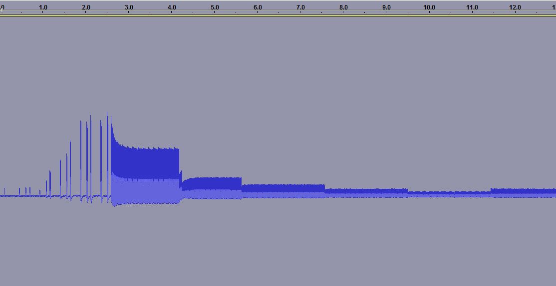
When you measure the energy out of a GSM cell phone at the moment of initiating a call, you get the picture to the right. It shows the first 15 seconds.
For the first 3.5 seconds there is the signalling between the phone and the base station. Then the connection is established, but after some time (at 4.2, 5.6, 7.5 and 9.5 seconds) one can see how the phone turns the power down, according to the commands it gets from the base station.
 The first example was for the case of a strong received signal, all bars are shown in the signal strength meter. The reduction in power, preservers battery life and as a side effect the user is exposed to a smaller amount of radiation. Interestingly, one can see that after a while there is a small adjustment of the power and it is turned up a bit (at 11.5 seconds).
 In other cases one can see a situation which follows the same pattern in time, except that the power stays at a high value. This second recording was done in my basement where GSM coverage is much poorer. Here the phone’s signal level indicator hardly shows any signal.
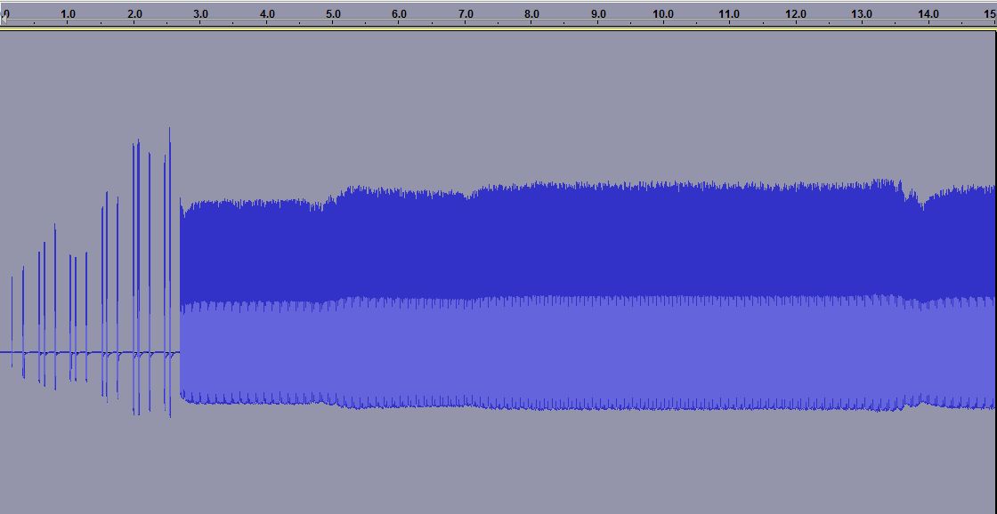

The third plot is a zoom of the previous one. Here one can see how the phone only transmits 1/8 of the time as it shares the channel with 7 other phones in a time multiplex. It is allowed to transmit every 4.6 ms and this is the reason why one often can hear a buzzing sound at 1/4.6 ms = 217 Hz in equipment which is placed close to a phone.
One also sees another frame structure, as the phone transmits 25 bursts and then breaks for one burst before continuing. Every transmission consists of 150 bits, but that is not possible to resolve with the simple setup that was used here.
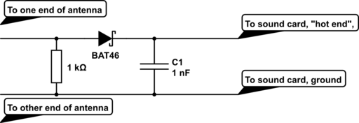
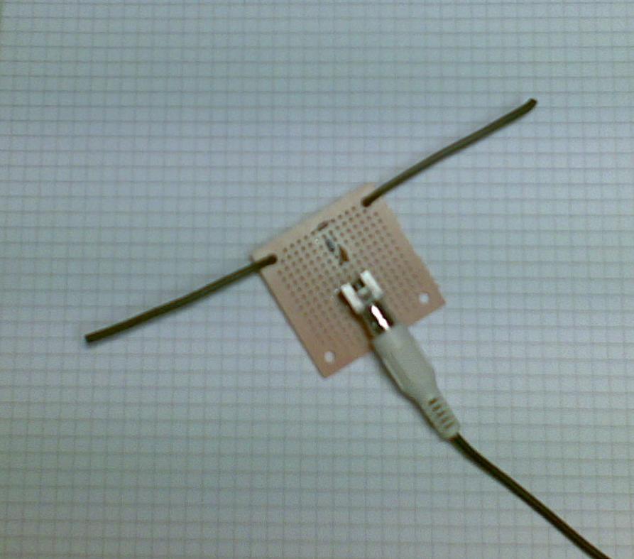 The equipment was a dipole antenna and a simple diode detector:
- A half wave dipole antenna for 950 MHz has a length of 0.5*3*108/950*106 = 15.8 cm, thus the antenna is about 2 x 8 cm (probably not very critical). The antenna was made from stiff self-supported wires.
- There is a resistor of R=1 kohm across the antenna and then a Shottky diode which acts as a detector (A Shottky diode which handles higher than 1 GHz is needed and BAT46 was used here), and finally a 1000 pF capacitor as a filter.
This post was inspired by William Andrew Steer’s “GSM phone signal analysis“.
A Useless Machine with delay and howl
The useless machine or ultimate machine originates from Claude Shannon, the scientist who figured out how to find the channel capacity in a communications system. I bought the basic machine as a kit from Solarbotics.
But then I added a few features:
- A delay circuit that makes it look more alive as it gives the impression of doing some thinking before it responds to the switch.
- Sound that varies with how open the lid is and the amount of light that hits the photosensitive resistor. It was inspired by the design of the Growl and Scream Altoids of FightCube.
- A couple of LEDs, a red one when it opens and a blue one when it closes.
The circuits were built on small pieces of veroboard and the circuit diagram can be downloaded from here. In retrospect I’m not completely happy with the sound, it could have growled and screamed even more, but then how much effort can one really justify putting into a project which is – useless – anyway?
All it needs is a title
I found this on a scrap piece of paper at the club last night. Being a bit thick and not knowing what it was for certain I asked a few people and the response was fairly consistent.
‘Its a…errr…y’know…..that you know used to do as kits for err’
Obviously I wasn’t the only one who was a little stuck. Well I don’t know what it is exactly, but I can have a few guesses – I’ll nail my colours to the mast and suggest it is a current meter of sorts. Anyone else care to join in the guesswork with more confidence? It took me long enough to find out what brass treblet tube is!


