Posts Tagged ‘homebrew’
 Ultimate QRSS kit
The kit building is carrying on at my garage before the cold weather comes and means that it’ll be less than appealing to go in there. This time it is a seemingly simple kit from Hans Summers, G0UPL called the Ultimate QRSS kit. Ultimate because presumably the kit does more than QRSS, however the kit is essentially a QRP (~150mW) beacon transmitter for QRSS and other modes, the attraction for me is that it also generates the tones for WSPR and as well as offering the QRP transmitter it also has the ability to generate just the audio for use with another transceiver. I was drawn to it because it offers the opportunity for a little bit of experimentation. Although things haven’t quite gone as smoothly as I’d hoped for.
The list of features for such a price is quite impressive. This is taken directly from Hans Summers’ website (http://www.hanssummers.com/qrsskitmm.html). Which is well worth a visit if not for this kit.
The kit supports the following modes:
– QRSS mode (plain on/off keyed slow CW)
– FSK/CW mode (frequency shift keyed slow CW)
– DFCW mode (dual frequency CW)
– WSPR mode (Weak Signal Propagation Reporter)
– Slow-Hellschreiber (frequency shifted slow-Hell)
– Full-speed Hellshreiber
– Half-speed ("DX") Hellshreiber
– CW (plain CW)
– Customisable FSK patterns
Other features:
– 24-character LCD + two-button user interface
– User-programmable (callsign, message, speed, FSK, mode, etc.), settings stored in EEPROM
– GPS interface, for locking the frequency in slow-speed modes
– On-chip generation of WSPR encoded message (no PC required)
– WSPR maidenhead locator can be generated from GPS-derived latitude/longitude
– Selectable “frame” size, for stacked QRSS reception
– Plain CW callsign identifier at selectable interval
– Produces 150mW RF output, or AF output for driving an SSB transceiver
– Higher output power by additional PA transistor and/or higher PA supply voltage
My 30m version has been sat on the shelf whilst the good weather (ahem!) was continuing. This came to head over the weekend when I warmed up the soldering iron and started piecing it all together. The kit took a few hours to build and I would image that a skilled builder would have it all together much quicker than I could with the excellent instructions.

Unfortunately on powering up things haven’t exactly gone according to plan. It only seems to power when it fancies it and certainly doesn’t generate the tones as you might expect although I am receiving a carrier roughly in the right area. The other small issue is that the LED doesn’t appear to do anything visual, this may be a design feature but seems a little bit odd to me.
 finished kit")
All these faults are almost certainly a result of my work, not the kit although it didn’t help having to scratch off the solder mask from the coil connections. I think the fault finding will take longer than the building in this instance but with a bit of luck it will involve some learning and there is no harm in that.
Still where’s the fun in it working first time?
My first 24 hours on WSPR

My first beacon on 30 m, a free-running Ultimate QRSS kit (no GPS) has now been running for a full 24 hours using the Weak Signal Propagation Reporter (WSPR) mode. The figure comes from the WSPRnet page.
With an output power of about 150 mW to an 80 m horizontal loop it has not been possible to reach beyond Europe so far. Perhaps this will happen in the future with better conditions and/or with some more output power.
Added 26.9.2012: I made it for the first time across the Atlantic!
Timestamp Call MHz SNR Drift Grid Pwr Reporter RGrid km az
2012-09-26 00:50, LA3ZA, 10.140262, -26, -2, JO59fu, 0.2, WB2EEE, FN21xh, 5852, 290
Altoids Projects
 |
| Press image for magnification |
I like to build small electronics projects and like many others I have found the small Altoids tins to be excellent enclosures.
These tins are inexpensive, well shielded, easy to work with, and least but not least they enable you to make experimental circuits that are sturdy enough that they can be reused later.
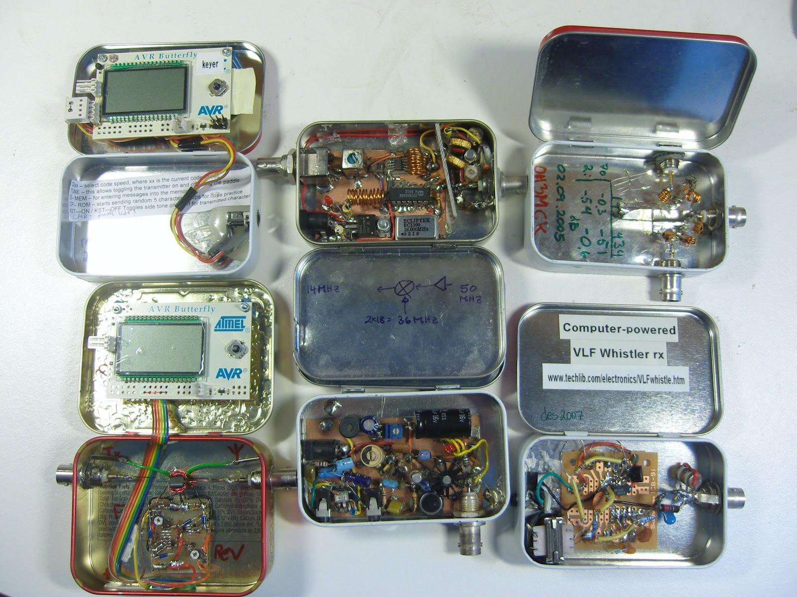
Pictured here is a collection of projects I have built over the years with the hope that they may inspire others.
To the left:
- AVR Butterfly morse keyer (KD1JV)
- AVR Butterfly Digital SWR / Power Meter for low power transmitters (KD1JV). Actually this project was built in the slightly larger Whitman’s tin.
In the middle:
- 50 MHz to 14 MHz receive converter (WA3ENK) with a low-noise preamplifier
- Pixie II QRPP transceiver for 30 m
To the right:
 |
| Press image for magnification |
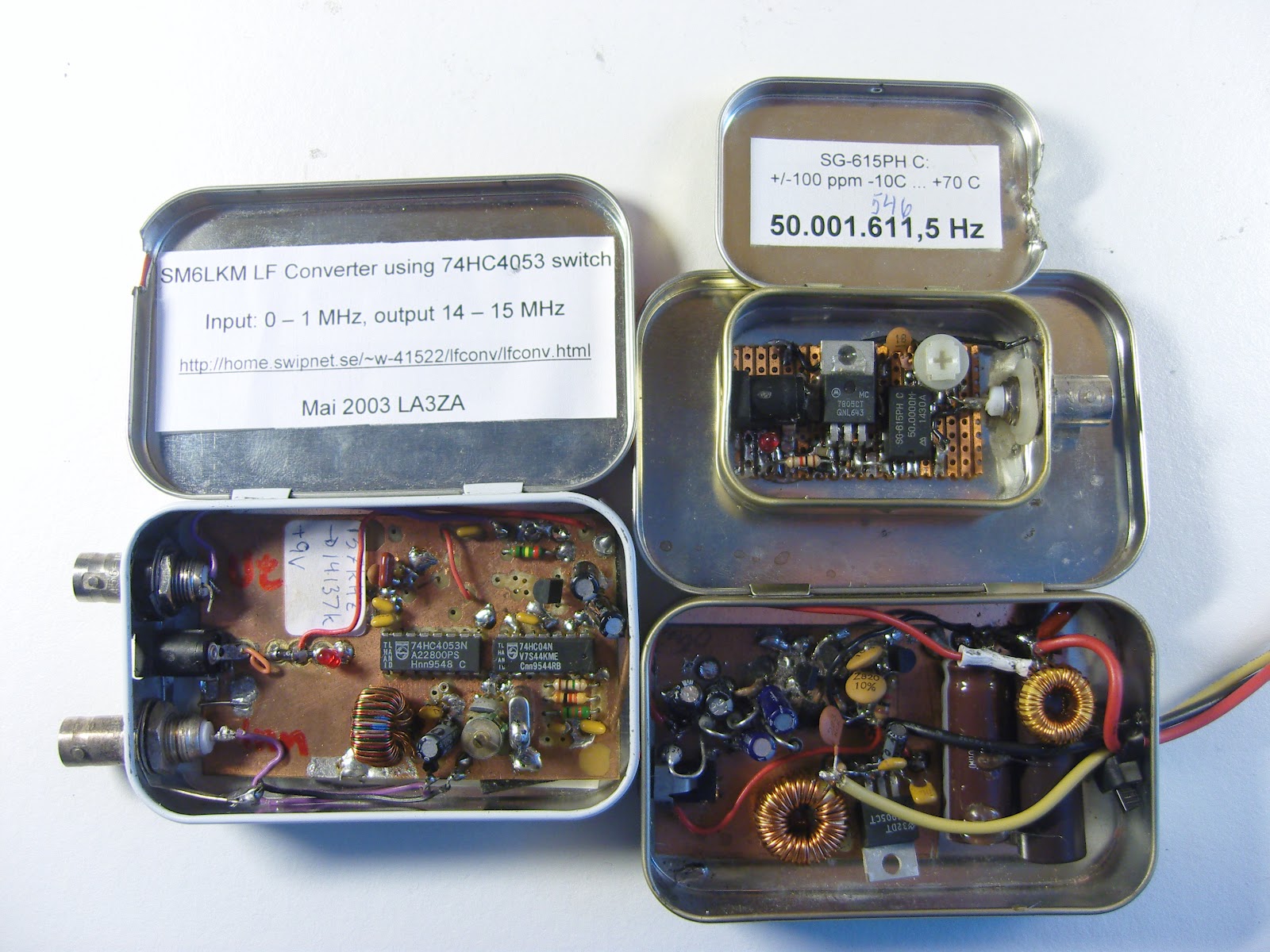
In the next picture there are some more projects:
- SM6LKM’s 4053 HCMOS converter from 137 kHz to 20 meter band.
- A 50 MHz test oscillator for testing 6 m receivers
- A switch mode power supply that converts 15 Volts into 4.5 and 30 Volts for a WWII miniature Sweetheartshortwave receiver. Design inspired by SM0VPO/G4VVJ’s practical voltage converter.
Here are some resources with tips:
- Maxim Tutorial 946: Disposable Metal Boxes Make Excellent Shielded Enclosures (via Dangerous Prototypes)
- Getting Started – Top 10 Small and Fun Electronics Projects – DIY Electronics
- Curiously Hackable: 8 Awesome Altoids Tin Hacks
- Altoids tin prototyping board (Make blog)
Added 17. September: Several of the comments on the page at Dangerous Prototypes are concerned with the difficulty of finding Altoids tins in many places of the world. That goes for Norway also. I have been lucky enough to have a job that allows me to travel to the US from time to time and then I have bought some. Ideas for local alternatives are needed!
Digital SWR meter final adjustments

Here’s the finished digital SWR and power meter kit from Radio Kits that is being used by the Workington Amateur Radio Club as a bit of soldering and coil winding practice. Not the poor lining up of the LCD screen. Shame really as the soldering was one of my better bits and that’s going to be covered up. All in all a nice kit to put together, I’m no soldering super star and I took my time so instead of it bring an ‘evening’ kit it I’d more like a ‘weekender’.
The case of the ……
Well Dr Watson, its wobbly metal.
Enough of the Tom Foolery and down to the serious business of an issue that must be fairly common. Drilling larger diameter holes in flexible metal sheet generally found on hobby cases. Just in case you were wondering though Tom Fool (aka Tom Skelton) is apparently a ghost of a Jester at our local castle, Muncaster so here’s hoping he’s had plenty of opportunity to wander round the house and grounds with odd shaped holes in his thin sheet metal parts.
A lot of trouble I have with when its time to put a project in a case is that the 16mm hole needed for an SO239 for example causes me no end of trouble. I have tried a number of different ways to make the holes without giving a figure of 8 or elongated hole. Step drills tend to give slightly better results that piloting and increasing the bit size. I have found that the latter can easily end up with a poor hole if any vibration is imparted into the case.
So what’s the answer, well, I just don’t know. Punching would seem to be a better solution as would routing the holes but in the case of pre folded sheet I’m sure this isn’t too practical. I’m wondering if people have had better results with other ways of making these holes.
Transformerless tube power supply
In 2012 bulky power transformers that work directly from the power grid at 50/60 Hz have mostly disappeared. My objective here is to modernize the power supply for a one-tube transmitter in the same way.
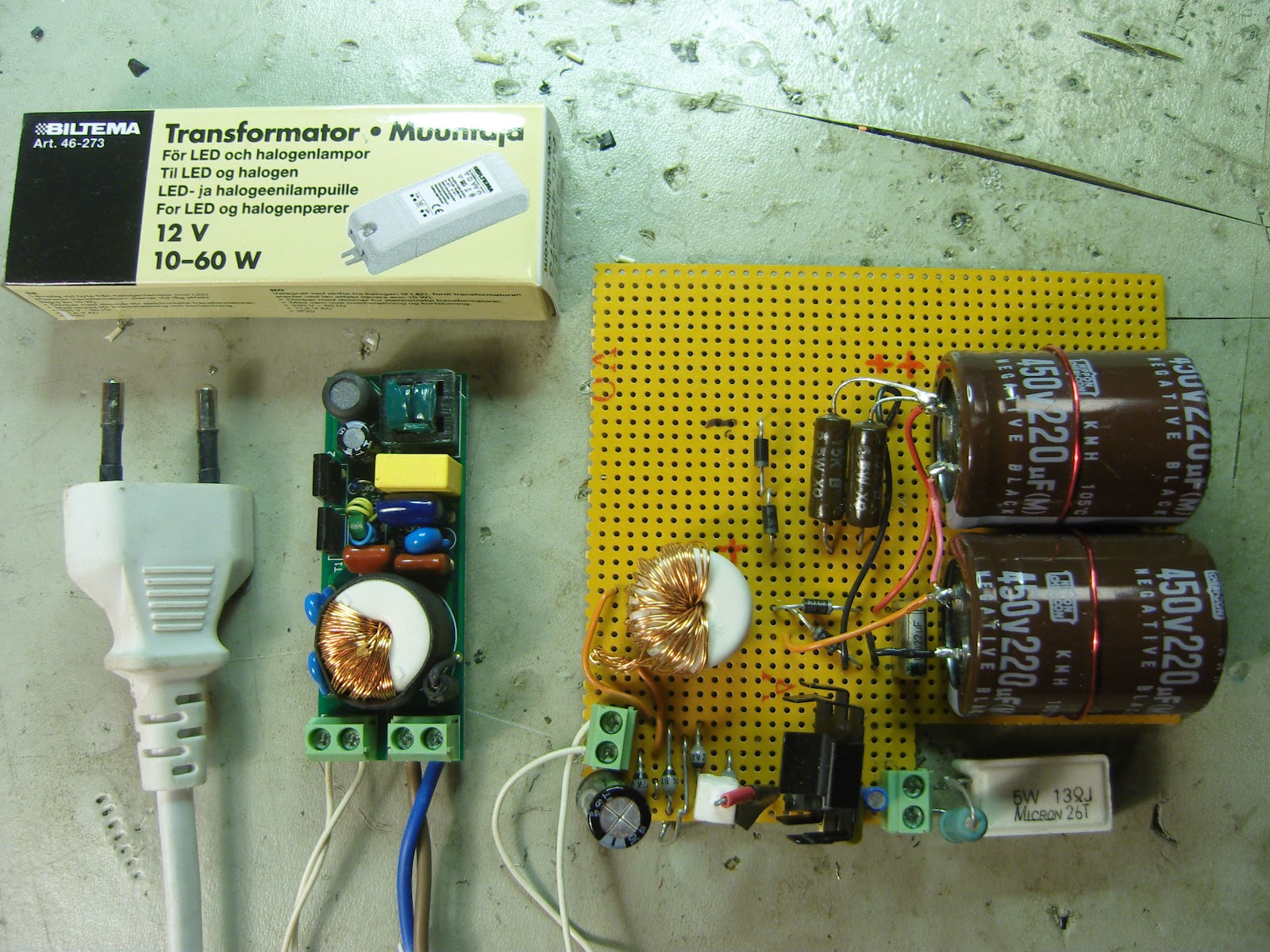
The circuit is based on an electronic transformer for LED or halogen lamps. Electronic transformers usually have a minimum power rating, below which they will not start. This one can tolerate a lower load than most and gives out 12 Volts for a load from less than 10 W and up to 60 W.
My target circuit is the AA8V/W8EXI 6CL6 one-tube transmitter (5 Watts or so). It needs 6.3 Volts for the filament (0.65 A), about 350 Volts DC for the plate and a regulated voltage of 200 Volts DC or so for the screen.
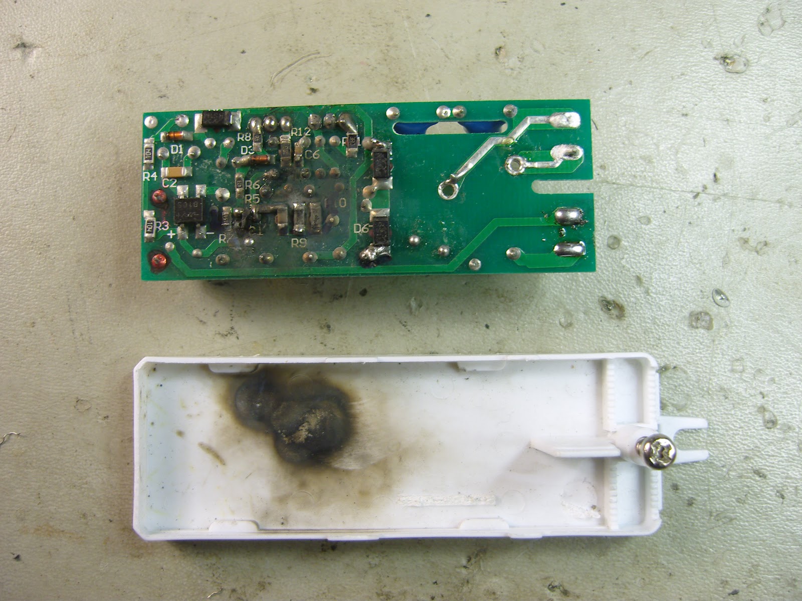
First I was inspired by DL2YEO and his Power Supply for small Tube Amplifiers. His approach was to redesign and rewind the high-frequency transformer (hmm, also a transformer, albeit a tiny one) of the circuit in order to get the desired high and low voltages. It takes some research to find the number of windings per volt and then to fit two secondary windings on the transformer which originally only had a single one. I tried this, but ended up with a burnt, shorted circuit. I concluded that it is too easy to make a mistake in this way.
My second approach was to reuse the small transformer from the burnt supply. I had to wind the original secondary back on it. The transformer is now reversed so the old secondary is used as the primary winding in order to step up the 12V AC. Then with a voltage doubler and filter capacitors I was able to get a DC voltage of 330 V. A series resistor and two 100 V Zener diodes in series gave me the regulated screen supply.
![]() The filament voltage is obtained from the 12 VAC, which is rectified and regulated with a LM317 voltage regulator to give 6.3 VDC. This is shown in the lower part of the veroboard where a load resistor that simulates the tube’s filament is attached to the green terminal block.
The filament voltage is obtained from the 12 VAC, which is rectified and regulated with a LM317 voltage regulator to give 6.3 VDC. This is shown in the lower part of the veroboard where a load resistor that simulates the tube’s filament is attached to the green terminal block.
Because the whole circuit runs at about 45 kHz, only fast-recovery rectifiers can be used, not the ones that are used at 50/60 Hz. The electronic transformer is from the Nordic retailer Biltema (part no 46-273, sorry no English web page).
I only hope now that this power supply won’t generate a lot of noise for the receiver.
Double Dip Weekend August 2012

Homebrew Buddipole inspection
Great weekend of QRP Portable fun. Saturday our Central FL QRP group had some new ops join us and we had a good time comparing antennas and rig setups at Sylvan Lake Park in Sanford, FL. As is typical, we did more talking than operating but did manage to sneak a few qso’s in on 20 and 17 meters. The contesters in Europe were hot and heavy on 15 m too so made for a fun day despite the heat and high humidity. I was a bit disappointed to not be able to snag any fellow Polar Bear QRP ops on 30m but the band did not stay open long and the other stations were operating on alternative bands.
Sunday after church was the first annual NJQRP Skeeter Hunt. So glad to work Skeeter Hunt promoter and fellow Polar Bear, Larry, W2LJ before the lightning ran me off. Larry was my last QSO of the day as a thunderstorm started making LOTS of noise and it was my signal to pull down the 31 ft Jackite and wire and get out from under the shade of the 50 ft tall pine trees down by the lake! YIKES… just made it too!
I ran my Sierra at 2.4 watts out into an end fed half wave suspended as a sloper from the 31 ft Jackite pole in a WNW direction. I normally use the trees to get a bit more height for my wire, but the Jackite goes up and down faster and with storms coming, I chose the simple and fast way to git ‘er done. Turned out to be a good choice. Band conditions were pretty good on 20m and I was hearing a good bit of activity. After 1800 the Caribbean, Central and South American SSB stations were causing a good bit of QRM down here in FL. They all seem to run power and gain antennas so we learn to listen through the chatter here in FL. The approaching storm was obvious as QRN increased with distant lightning stirring up the noise and crashes. Nonetheless, the signals were pretty good despite the distractions and there were some SKCC, FISTS and other cw fans out there having fun too which made the band busy.
I built a simple key and am posting a photo of my K4UPG Knee Cap Key. Used the lid of a bulk black peppercorn jar and made a simple non-iambic key with paper clips, standoff and a bit of wire. It actually worked fairly well, but not good enough to use for the whole contest. As a long time CPG (Contest Point Giver) I decided that was a good way to give myself some points so took advantage of the bonus points! It did inspire me to try a more substantial lid and make a strap to use it as a leg key for portable ops.


Umbrellas for the rig and the op!
It was fun to hear so many familiar calls and work a few of our fellow Polar Bear Ops who were out for the fun too. Sure appreciate the effort to put this event on the calendar and process the results. Thanks to the NJQRP group for the support of our niche in the hobby and to you Larry for the time you devote to contests, blogs and getting us all out and on the air.
Here’s my results before the storm drove me for cover:
| Date | Time | Call | Band | Pwr | RST | RCV | SPC | Nr | |
| 8/12/2012 | 17:12 | N0SS | 20 | CW | 2.4 | 559 | 579 | MO | #122 |
| 8/12/2012 | 17:17 | W0EA | 20 | CW | 2.4 | 559 | 559 | IA | #22 |
| 8/12/2012 | 17:23 | NK9G | 20 | CW | 2.4 | 559 | 559 | WI | #75 |
| 8/12/2012 | 17:25 | VE3WDM | 20 | CW | 2.4 | 559 | 559 | ON | #15 |
| 8/12/2012 | 17:37 | KQ2RP | 20 | CW | 2.4 | 449 | 439 | NJ | #27 |
| 8/12/2012 | 17:39 | AB4PP | 20 | CW | 2.4 | 579 | 599 | NC | #79 |
| 8/12/2012 | 17:42 | N0JRN | 20 | CW | 2.4 | 559 | 559 | MO | 5W |
| 8/12/2012 | 17:46 | N3AO | 20 | CW | 2.4 | 449 | 559 | VA | #109 |
| 8/12/2012 | 17:49 | W4MPS | 20 | CW | 2.4 | 599 | 559 | NC | 5W |
| 8/12/2012 | 18:00 | KR9Z | 20 | CW | 2.4 | 449 | 449 | IL | #10 |
| 8/12/2012 | 18:06 | AA4GA | 20 | CW | 2.4 | 579 | 569 | GA | #2 |
| 8/12/2012 | 18:08 | N7UN | 20 | CW | 2.4 | 579 | 559 | NJ | 5W |
| 8/12/2012 | 18:14 | WF4I | 20 | CW | 2.4 | 559 | 559 | NC | #71 |
| 8/12/2012 | 18:18 | K3RLL | 20 | CW | 2.4 | 449 | 339 | PA | #21 |
| 8/12/2012 | 18:31 | KX0R | 20 | CW | 2.4 | 449 | 359 | CO | #69 |
| 8/12/2012 | 18:36 | W2LJ | 20 | CW | 2.4 | 579 | 599 | NJ | #4 |
A good time was had by me!
72,
Kelly K4UPG


