Posts Tagged ‘homebrew’
 Barn Door CLE Regen Results

This past weekend's 'Barn Door' CLE' saw a lot of participation, in spite of the mid-summer doldrums and the universal nasty lightning noise.
After reading CLE-organizer Brian Keyte's interesting posting to the ndblist, describing his homebrew single transistor regenerative receiver, I was inspired enough to dig out the soldering iron and build one for myself.
The circuit widely described as a '1AD regen' was originally designed several years ago by crystal-radio guru Mike Tuggle out in Hawaii. Mike is widely known for his exquisitely designed "Lyonodyne" DX crystal radio, which inspired an entire decade of intense DX crystal radio building activity back in the late 90's.
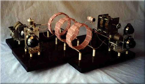 |
| Mike Tuggle's 'Lyonodyne' DX Crystal Radio |
His '1 Active Device' medium-wave regen consists of a handful of simple components and a MOSFET that is up to the task. His design was, and still is, being duplicated by many throughout the NDB DX listening community.
 |
| Mike's original 1AD regen |
Mike recently sent me the circuit diagram that he eventually settled with, showing two possible ways of extracting audio with the widely popular Bogen T725 output transformer.
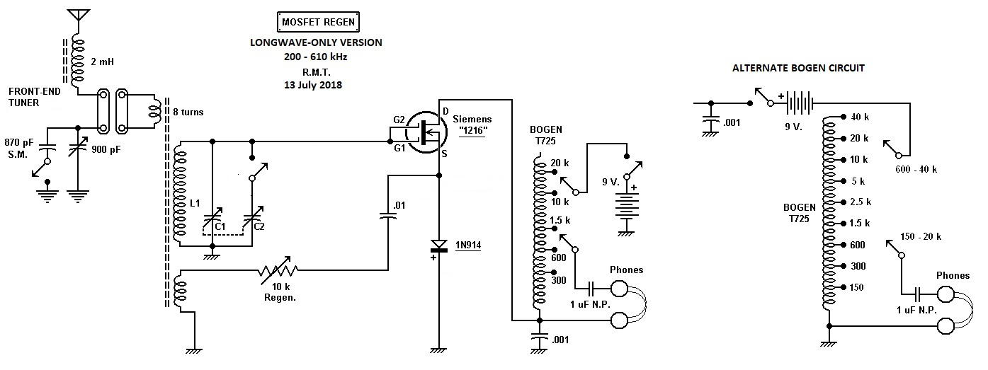
My own version used Mike's output scheme on the right and the RF circuitry in Roelof Bakker and Steve Ratzlaff's modified version, shown below. I had to increase the tickler (feedback) winding from 4 turns to 11 turns in order to get any regeneration. With 11 turns, my regeneration kicked-in at about three-quarters from the end of the regen control. At some point in time, while testing, some of the leads from my Bogen T725 output transformer momentarily brushed against each other, smoking my FET. Upon replacing it with another BF966, the receiver was much hotter, with regeneration kicking-in very close to the start of the pot. I'm not sure if the first FET was already damaged or that there is enough variation from FET to FET (of the same type) to make some have more gain than others. Accidentally blowing up the FET proved beneficial in the end!
Although most users employ sensitive sound powered headphones with their regens, including myself, some use modern phones with an extra stage of audio, such as an LM386.
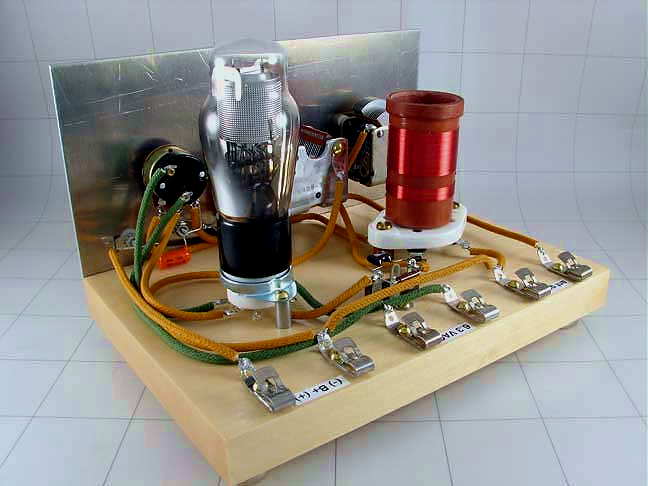
Although not nearly as pretty as Mike's regen, my own 1AD was built in an afternoon, just for the recent Barn Door CLE.
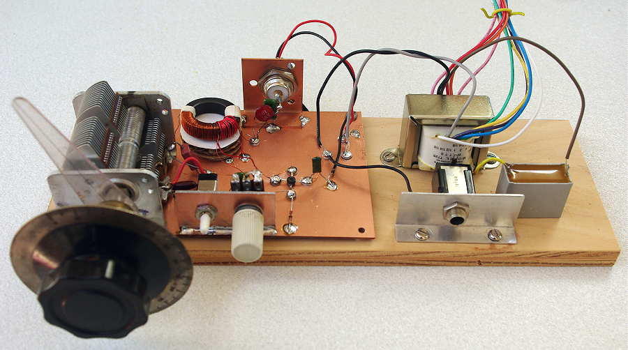 |
| My own MW 1AD regen |
I later added a calibrated dial plate, breaking the segment from 200kHz to 550kHz into two separate bands, with calibration ~ +/- 1kHz so that I pretty much new where I was tuning at all times. This allowed me to target specific beacons and wait for them to fade up.
When first published, Mike suggested the BF966 MOSFET seemed to work well and I purchased five of them with the intention of someday building a 1AD for the NDB band. The purchase came in handy, as today, the BF966 is no longer available. Apparently the similar, and still available BF998 works well (from tests done by Steve Ratzlaff) but is now in an SMD package at just 18 cents! No doubt there are dozens of MOSFETS that will do the job and at these prices, experimenting with various devices would be a very worthwhile project.
When operating, the regen proved to be surprisingly sensitive, and by using my 10' x 20' loop, I was able to put my local pest (AP-378 kHz and 1/2 mile away) into a deep null so that its huge signal was no longer blocking the top half of the NDB band. The null allowed me to hear beacons within a few kHz of the blowtorch signal as shown below:
I ended up with 70 stations logged, including a couple of Alaskans, in spite of the horrendous lightning noise on all three nights. Doing another 'Barn Door CLE' in the middle of the quiet DX season would be much more exciting and several 1AD users have indicated an appetite for such an event. If you put something together please let me know as having an army of 1AD's ready to go would be a great incentive to schedule another Barn Door weekend!
Barn Door Wide!
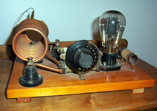
 |
| Alfred Morgan 1 Tube Regen courtesy: KC9KEP |
The next CLE event will be the "Barn Door" listening activity which requires listeners to use receivers without the usual narrow filters. Some of the older tube radios can do this easily as can most homebrew receivers ... especially the regens!
If you've never listened to the NDB band with a wide bandwidth, it is a fascinating experience! If conditions are normal, you can typically hear a half dozen or more signals, all at various pitches, vying for your attention. It's almost as if you have plunked yourself down in the middle of the NDB forest of signals, and they are coming at you from all directions.
Many choose to use one of their homebrew receivers for this event, often as simple as a '1AD' or a '1 Active Device' circuit. A recent posting to the ndblist group from CLE organizer Brian Keyte (G3SIA), described just how much fun can be derived from such a simple radio. I'll let Brian's words speak for themselves below:
Recently I've had a few requests to provide details of my 1-transistor receiver, as used on my recent Scotland holiday and back in April 2009 for our first CLE for simple receivers. (There's still time to try making something for our next CLE145).
Here goes:
In March 2009 I was tempted to try following in the footsteps of Mike Tuggle and Finbar to see if I, as a complete D-I-Y beginner, could make a very simple 1-transistor NDB receiver. The story of making and using my own '1AD' (single active device) may help anyone also wondering whether to try some simple D-I-Y construction for CLE145, our second Listening Event for basic receivers.
I started by rounding up some likely old radios and a TV from my junk box and tried to see what I had in them that might be useful for a 1-transistor regen. receiver. From a list of the transistor types that I'd found, Mike identified a BF362 as probably the only suitable one. It is a 'normal' N-P-N silicon transistor (a BJT - bipolar junction transistor - as opposed to a field effect transistor like the MOSFETs) and is intended for low power high frequency applications. My background in making anything using transistors was just about nil and I knew almost nothing about them. The first challenge was removing the BF362 from its circuit board (a small board designed to amplify incoming UHF TV signals). Trying to play safe, I sawed round a big chunk of the actual board having snipped off most of the other components. A bit of brute force was needed as well as the hacksaw. Tests with a meter then showed that I should be able to solder to Collector, Base and Emitter without overheating the transistor. (Google helped when I entered ' BF362 data sheet ').
From the discarded MW / LW receivers there were several 2-gang variable capacitors and their tuning coils wound on ferrite rods - and of course lots of fixed capacitors and resistors. Many years ago a friend had passed to me the result of his construction of a basic amateur receiver (Heathkit RA1). That was useful because of the lack of a circuit board - the components were just soldered to lugs, most with still usefully-long wires. It also had a full list of parts and simple advice on construction. One of the old portable receivers I'd found had a plastic case that looked suitable for housing things (about the right size and shape, easy to drill, etc.).
First I tried a lash-up of the basic components on-the-bench (i.e. on the dining room table!) using the simplest transistor circuit without any regen. Trying my normal aerials, including a 100 metre long wire, I could weakly hear a few broadcast stations in the LF part of the MW band. Complete silence where there should have been NDBs - and my nearest, 316 EPM, is only 5 km away. When I tried adding regen. it proved to be an uncontrollable beast - stray capacitance effects due to all the loose connecting wires, etc. (I had made no use of a soldering iron yet!).
It seemed there was nothing for it but to start mounting the main components in the case - something I had wanted to do only after getting some real results. I had to try and guess where to site the components for likely best performance, ease of operation, etc. With no metal casing, it seemed to be a good idea to put a grounded copper wire as a 'busbar' round part of the case. That might help reduce any hand capacity effects and it would be useful for making the several ground connections including the '-' side of the little PP3 9v battery. Where possible the metal cases of the potentiometers were grounded to it too.
I had only just started fixing components in the case when Sue and I needed to move up to Lincolnshire for 5 days. That turned out to be good, as I would be well away from temptations to continue the component searches for 'something a bit better' and I could concentrate on what should be the fun part. There was a good ground connection there but I was limited to a 30 metre long wire aerial. With regen. working, that proved to be long enough to get some results from Broadcast stations, though still not loud. I was making slow progress by trying out different component values etc. and by the time came to come back home I had only heard TWO beacons. One, 338 FNY Doncaster/Sheffield International (Robin Hood Airport), only 15 miles away, was faint but fairly easy to find. The other, 365 KIM Humberside and also about 15 miles away was very faint and I only managed to hear it once. Listening during the evenings didn't add any more NDB loggings at all. I was very disappointed and ready to give up the project, but Sue reminded me I had said that if I heard just one NDB during the 5 days I would consider it a success!
Returning to Surrey my luck changed. Without making any alterations, I tried the set using my 100 metre long wire - and it was transformed! During a few minutes at dusk I heard about 25 beacons, mostly weak but clear - the 30 metre aerial in Lincolnshire must have been the problem. Listening briefly again later that evening, several European countries were there - and to my surprise I suddenly stumbled on OZN 372 (Greenland) among the loudest and clearest. That made me wonder if a Canadian beacon was possible, so I tried for DF 350 more or less at random as one of the more likely ones. Setting the receiver to 350 kHz could be difficult with no frequency markings yet, but then I noticed that it would be halfway between my locals FOS 348 and WOD 352, both of whose idents could be heard at the same time. But no luck!
Then, at about 01.15 and just before bed, I tried again. After a minute or two there appeared a weak intermittent carrier and then - sure enough - about 5 cycles of a definite 'DF' before it faded and was gone. Can you imagine my delight? Ten days after starting as a complete D-I-Y beginner, a 1-transistor device made entirely of a few junk box components was getting me Deer Lake, almost 4,000 km away (2,500 miles) in Newfoundland. After that I thought the set justified having a name, so it was christened 'Max' (contradicting its minimal design!).
The next morning I took Max to try it out when genuinely portable using a long fence not far from here. Midday conditions this time but, with the necessary short aluminium rod pushed into the ground, it gave around 25 beacons in about 10 minutes, including Wales, Belgium, Guernsey and France. Another advantage of a simple portable receiver - there are lots of places with very long ungrounded wire fences that I've noted on our walks. Then at the end of the month Sue and I had a week's holiday at a self-catering cottage on the Isles of Scilly, 50 km into the Atlantic off the far South-West of England. Travelling by train and ship (no car), my AR7030 receiver and power supply couldn't make it into my rucksack but Max did, a fraction of the weight, together with about 100 metres of light wire to drape on the hedgerows beside the cottage. Listening mainly at daytime I heard over 100 NDBs. Again, the signals were mostly quite weak, but crystal clear.
Back home I made a few overdue improvements - replacing most of the remaining twisted wires with soldered connections, fitting a terminal block for the aerial and earth, adding a little switch to select one or both of the capacitor gangs and changing connections in the output transformer giving a considerable increase in volume. I had wondered whether my reception of DF had really happened, despite the detailed notes that I had made at the time. Then early one morning there was DF again, much louder than before and it persisted for several minutes.
I used the set of course for our first 'Barn Door' listening event for basic receivers, CLE116, during Easter weekend 2009. I chose to listen only within two hours of midday using a long wire or one of my fixed passive loops and I just managed to reach 100 NDBs. 14 of the loggings were of beacons over 400 km away.
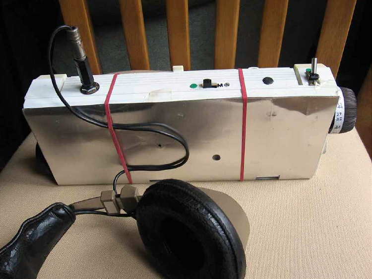
In June this year, with CLE145 coming at the end of July, Max needed to be re-awakened and tested before taking it with us to Scotland. It had always suffered a little from hand capacity effects - touching some parts caused minor changes in frequency, as did the aerial being blown about by strong winds, etc. I discovered that one of my old PC keyboards had a big metalised screen under the keys. This cured all those problems merely by placing it (fixed with rubber bands!) over the front of the receiver. It also stops an occasional 'fizzing' kind of interference if I slide the first few inches of the headphone lead under the rubber band to hold it against the screen (see picture). I assume that problem was caused by some kind of RF getting through to the 'phones.
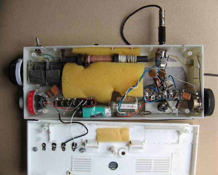
The attached pictures show Max's front view, the inside view with the back cover unscrewed and the circuit diagram.

In the front view the main tuning knob is at the top right hand side, still with primitive frequency markings on it! (35 = 350 kHz, etc.).
The regen. control is just visible at the bottom left hand side.
The top right hand switch extends the tuning range below 300 kHz by adding the second half of the variable capacitor.
(The top central switch is a refinement that allows the tuning to cover just the Medium Wave broadcast stations by using a different winding).
In the inside view, the main components are:
The transistor on its hacked bit of white circuit board which can be seen centre right.
The windings on the ferrite rod at the top are, left to right, the original main tuning coils, aerial coupling and the regen. coil.
The bottom right potentiometer is the regen. control.
The 'floating' pot. is the base bias control.
The large top left knob is main tuning, (I tried adding a fine tuning capacitor in parallel, but it added operating complication without any advantage and I removed it)
The bottom left pot. (still as in the original set) is spare, but it incorporates the battery ON/OFF switch.
The battery, wrapped in plastic in case it shorts things, can be changed using the hinged flap.
(However the battery drain is about 1 mA, so the battery would last for many months if I listened for an hour every day!)
The output matching transformer is next to the battery.
As you can see, my approach has been very 'Heath Robinson' and a real hit-and-miss affair, so don't put much reliance on it. The set does work pretty well, but I'm sure circuit design experts will see lots of things than could be improved - and not just the quality of the soldering! Others are likely to use different transistor types and component values and some connections may be different. A MOSFET would be expected to perform better.
In case you haven't used a regeneration set before, the regen. control allows feedback of some of the RF signal to the main tuning circuit. As the regen. knob is increased from zero it increases the apparent signal strength considerably. Broadcast stations get much louder and a very local NDB would just be heard from its audio ident (a 400 Hz or 1020 Hz Morse tone). Turning the regeneration control up further continues to increase the signal strengths until suddenly beat notes start to be heard when you tune across any carriers. Now you hear the NDB signals much as 'real' receivers would when using their CW setting and no filter (or a very wide one).
The regen. could be increased even further, but eventually the set starts to fizz or wail loudly and becomes a 'dirty' transmitter - not useful!
If you have read as far as this you must have already built a simple set or are at least a bit tempted to!
If you have a little spare time, do give it a try. It really is a fun project and when you start to get results it is like reliving all over again those early days when you were delighted by your first DX loggings - only this is even more satisfying!
I'm grateful to Mike and Finbar for their encouragement and suggestions. I sent details of their sets to the List on 10th June in my email introducing the 'Barn Door CLE145' in late July. It would be good to hear details from any others with working sets or who are well on their way to having them.
Good listening!
Brian
Now if this is something that might interest you, filling a log page of NDBs heard on your own little creation, then there is still plenty of time to whip something together. If you prefer 'modern', then Mike and Brian's circuits might be a good place to begin experimenting or you could just grab one of your old Handbooks and check out the simple regenerative circuits described ... from the '30s on up! Just beef up the L and C values enough to get you down below the broadcast band and you're in business.
There is also a ton of stuff on the web via the vintage magazine and book collection available at the American Radio History website here, with enough info to keep you at the workbench for a long time.
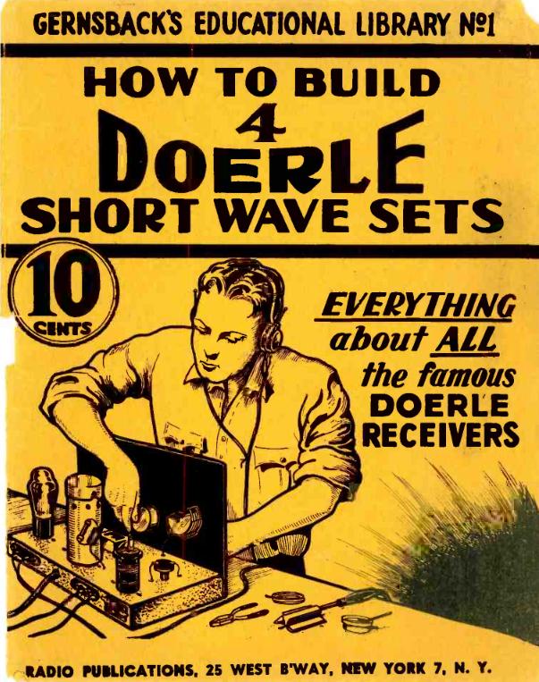 |
| courtesy: American Radio History |
Here is the CLE info, direct from Brian:
Our 233rd Coordinated Listening Event is only just over, but Joachim and I
want to tell you a little about something special coming for our next CLE,
27th - 30th July.
For CLE234 we’ll have one of our occasional ‘Barn Door’ CLEs.
It will be an opportunity to bring back to life basic kinds of receiver -
anything with low selectivity which allows you to hear NDBs on several
frequencies simultaneously – “leaving the barn door wide open!”.
Our last Barn Door CLE was No. 209 in July two years ago.
Listening with 'back to basics' equipment often gives very satisfying and
unexpected results. It can also show us ways of improving our listening
when operating more normally.
To take part, you could use any one of the following:
1. A simple home-made receiver, such as a single transistor set with regen.
(e.g. based on the sets used by Mike Tuggle, Finbar and others).
2. OR - an ultralight receiver (maybe one converted to cover the NDB
frequencies with a modified aerial).
3. OR - an 'antique' receiver brought back to life (e.g. Scott,
Eddystone, R1155, etc.). Most of those are anything but ultralight!
4. OR - a normal receiver but with NO filtering, or using a WIDE FILTER,
(not less than about 2 kHz and with no selection of an audio filter).
Your 'barn door' should be open wide enough for you to hear any NDBs
on at least five adjacent frequencies all at the same time - E.g. NDBs on
348, 349, 350, 351 and 352 kHz with the receiver set to 350 kHz.
Listening to one NDB and ignoring several others of different pitch can be
quite a challenge - but it is very satisfying when you find how quickly it
becomes easier to do.
It may take a while to prepare for some of those ways of listening,
especially the first - hence this ‘Early Warning’!
The attached guide *** (click here) from the past by Mike Tuggle may help you if you are thinking of using a basic D-I-Y receiver.
The ‘Early Advice’ and ‘Final Details’ for the CLE will follow about 9 days
and 6 days before the event, earlier than usual to help you to get ready.
Good Listening!
Brian
-----------------------------------------------------------------
From: Brian Keyte G3SIA ndbcle'at'gmail.com
Location: Surrey, SE England (CLE coordinator)
----------------------------------------------------------------
Trouble Free HF Antenna For The Apartment Dwelling Ham
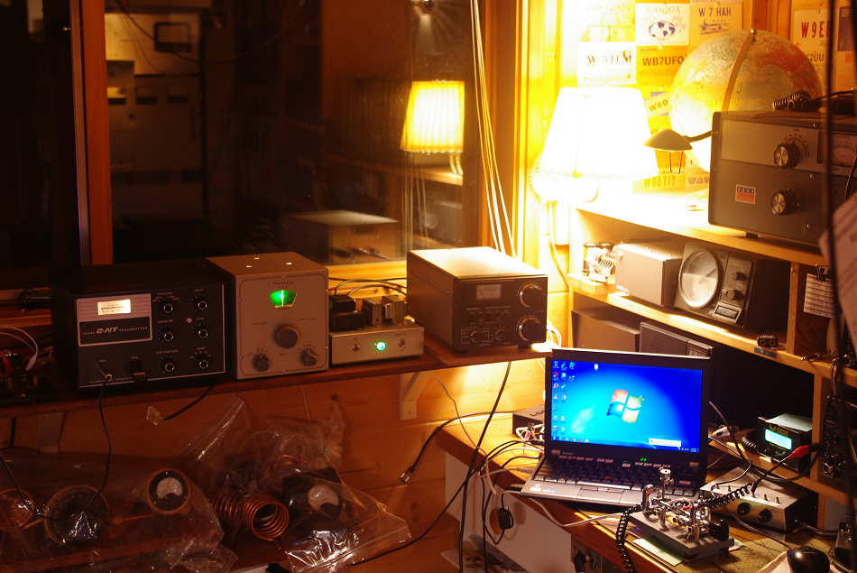
 Unfortunately we all know of or hear about hams that have given up all hope of getting on the air, once moving into an apartment or condo, where antennas are normally prohibited. One enterprising local amateur has combined early established antenna fundamentals along with sound engineering, to arrive at an elegant and highly successful solution. If you are also a 'location challenged' amateur, it may just be the thing that will help you, and others, take back your hobby and get on the air!
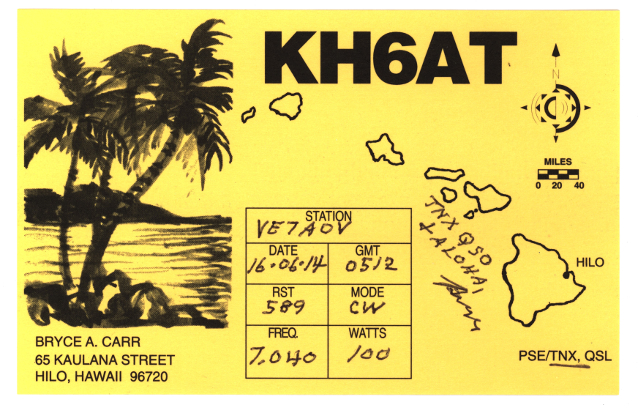
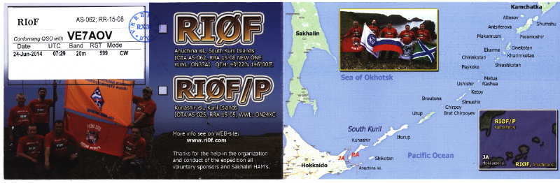
John, VE7AOV, has been operating from his apartment, in the heart of the very large and noisy greater Vancouver, for several years now ... not simply 'operating', but thriving, from his cozy fourth-floor apartment radio station. The wallpaper shown below would not usually be expected to grace the shack walls where antennas are not permitted!


It's soon apparent that John has also overcome the usual problem of noise ingression, from every appliance and random RFI generator in the complex. This is no lucky fluke but all by design, and delivered via an all but invisible classic antenna system made of #26 wire and a few Starbuck's stir-sticks!
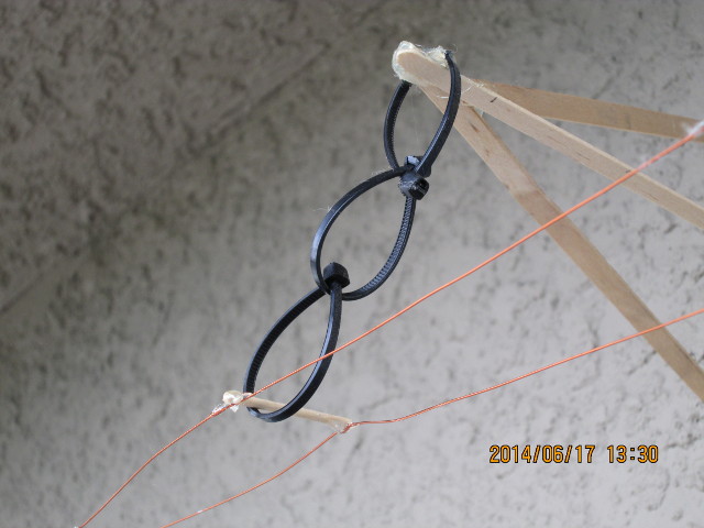 |
| 600 ohm #26 balanced line |
I'll let John tell you a bit more before sending you to his fascinating website, Intuitive Electronics, where you can learn more about his system and the engineering behind his successful, low-noise installation.
When it comes to a high frequency ham station, the antenna alternative chosen by most apartment dwellers is no antenna at all. The design here is a wisp of an antenna that bothers no one and which can work Japan, Australia, France, European and Asian Russia, the Caribbean, Central America, Polynesia and South America from the Pacific coast of Canada. It is a simple solution for apartment dwellers, it is a cheap solution and it causes no t.v.i. or other r.f. problems. It is far preferable to the alternative selected by so many fellow apartment dwellers: no antenna at all.
An implication that it seems to be impossible to rid from the minds of fellows using a Marconi antenna is that they are not just pumping 100 watts of r.f. into their antenna but that they are also pumping that same 100 watts of r.f. into their ground, that is to say the building’s wiring, the safety ground wiring. R.f. in the safety ground is well coupled into the power and neutral conductors of a residence and, in North American code, is even hard connected to the neutral line at the service entrance. The house wiring becomes part of the antenna system.
The ground wiring and everything connected to it is every bit as much a part of the antenna as is the live element. Both radiate just the same amount of r.f. power, fellows. The ground wiring along with every electrical power consumer in the building is worked against the live element. Thinking of what is connected to ground in your house is thinking about one side of your antenna. It’s not just appliances that get the “benefit” of r.f. The land line telephone system, the cable television system, the garage door opener, the security lights and…you name it. They are all “feeling” that 100W of r.f. With regard to r.f., there is no distinction whatsoever to be made between “hot” and “ground”.
You know the reason why vertical antennas have gained a reputation for being noisy on receive now, too. Most verticals are Marconi antennas. Both the safety ground and the neutral serve all the houses in the neighbourhood. The receiver is wired into the electrical appliances of the entire neighbourhood.
This radio station, located four stories above grade and in a wooden building full of apartments would be a worst case for r.f. in “ground”. This station has no r.f. in the station. It has no r.f. in “ground”.
The station has no interference issues. The Building Manager, the Building Superintendent and the administrator for this building’s cablevision have been aware of the station from the beginning. There has not been a single complaint of t.v.i. or any other complaint about the station. That’s a clean record extending back to 2006. There are no red faced, spluttering tenants hammering on the door of this station! At this station, all the r.f. produced by the transmitter makes its appearance out on the antenna. The radio station’s r.f. is not referenced to station ground. Station ground “knows nothing” about the r.f. being generated.
In the present case, that is to say a station to be operated in an apartment building, it is required to have an antenna that is “invisible”. Now it’s not possible to achieve that literally but at least the antenna should be so inconsiderable that there will be no complaints from neighbours about having to look at it. The antenna here is made of #26 A.W.G. wire. That’s wire that is 0.40mm, 0.016 of an inch, in diameter. Four stories up, it’s difficult to see the antenna and that’s even when knowing where to look for it. Part of the antenna’s run is through trees and in among the tree branches it pretty much is invisible. It does not annoy neighbours by casting a shadow; there is no shadow.
In spite if the naysayers, John's small gauge antenna has survived years of winter storms, regular occurrences here on Canada's western edge ... simply because it presents such a low cross-section compared to most conventional antenna wires.
To read more about enjoying your hobby again from your new 'restricted' location and more than likely, learn something new about old fundamentals, give John's website a very close inspection ... there is much wisdom and many gems to be found, even if you don't live in an apartment!
Power regulator works as polarity protection
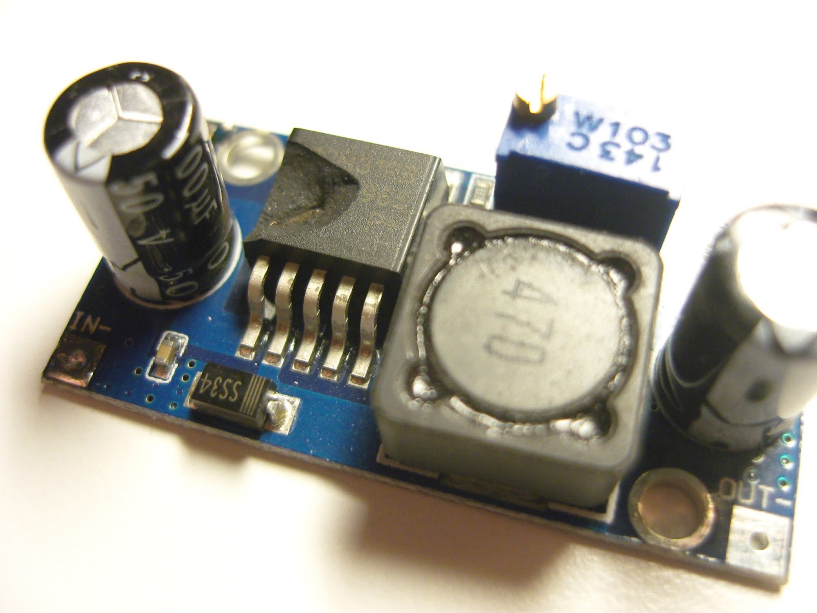 |
| Step-down converter based on LM2596. Note the damaged chip |
Ok, now I’ve done the test. My QRPLabs U3S runs off a 12 Volt power supply. There are two step-down converters, one for 5 Volts for the processor and another adjustable one for the power amplifier, if one can call 0.2-0.5 Watts a power amplifier. See picture of these voltage converters in this post.
I happened to make a new cable for 12 Volts which had the polarities inverted – and puff – there was a noise and absolutely no response from the U3S. I feared that I had blown the entire circuit. As my power amplifier was turned off, only the 5 Volts supply was affected and upon inspection I found that the voltage converter had a destroyed chip.
Since since they are so cheap, I had a spare. Luckily for me, the U3S worked as it should after replacement. So the LM2596 can take a reversed polarity and sacrifices itself in order to protect the rest of the electronics. Nice!
This post first appeared on the LA3ZA Radio & Electronics blog.
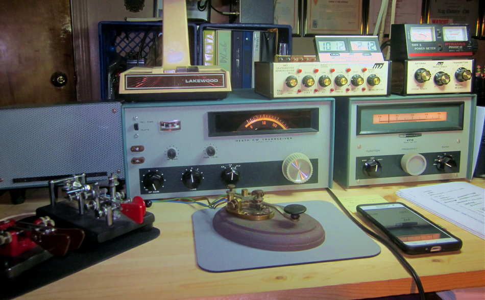
My 2018 Novice Rig Roundup (NRR) Highlights
 |
| courtesy: arrl.org |
Well this year's NRR has come and gone, providing a full nine days of CW fun for those of us that love old radios.
Once again, the ether filled with signals spawned from the old classic Novice-class workhorses that many of today's 'seasoned' amateurs used in their first stations, way back in their teen years. In many respects, the NRR is as close to a real time machine that you'll find, allowing participants to experience the joys, and sometimes the frustrations, of operating CW with their favorite old rigs from the past.
For me, just like last year, the NRR once again provided many notable highlights over the nine day event.
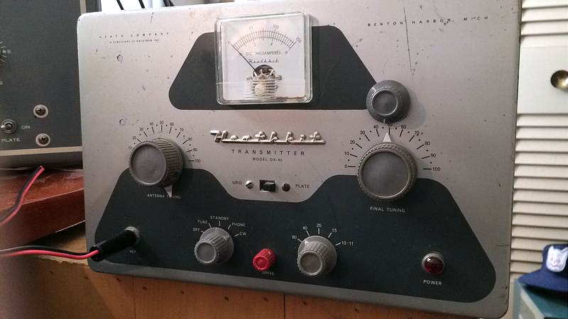
Almost topping the list was just experiencing the variety of old classics and hearing how well almost all of them sounded. Numerous Knight T-60s, Drake 2NTs, Heath DX-40s, Johnson Adventurers and Eico 720s, along with a nice variety of homebrew MOPAs and one-tube power oscillators graced the nightly airwaves. These oft-forgotten shelf-queens always seem to develop super-powers, far beyond their expectations, when the NRR rolls around!
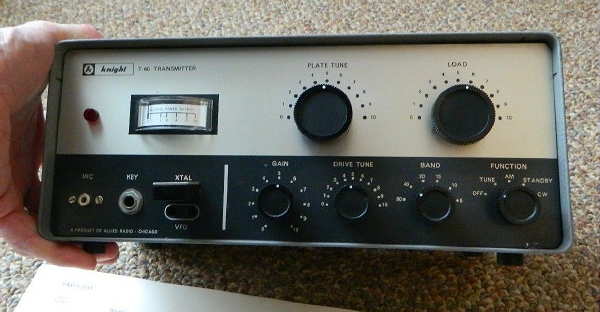
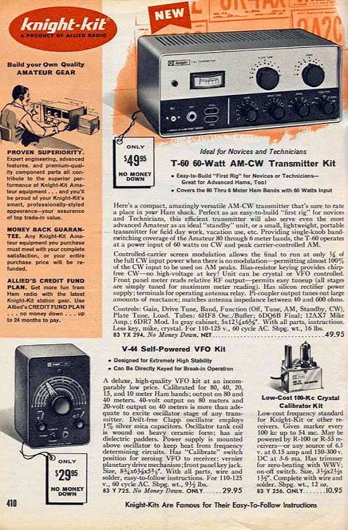
I was really surprised to work so many T-60s, a small and inexpensive 60 watt transmitter kit from 1962 using a popular 6DQ6 television sweep tube ... one never expected to achieve such RF greatness! I was very impressed with every one that I heard.
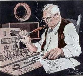
What radio-struck pre-Novice teen, dreaming about getting on the air, could resist a clever ad like this.
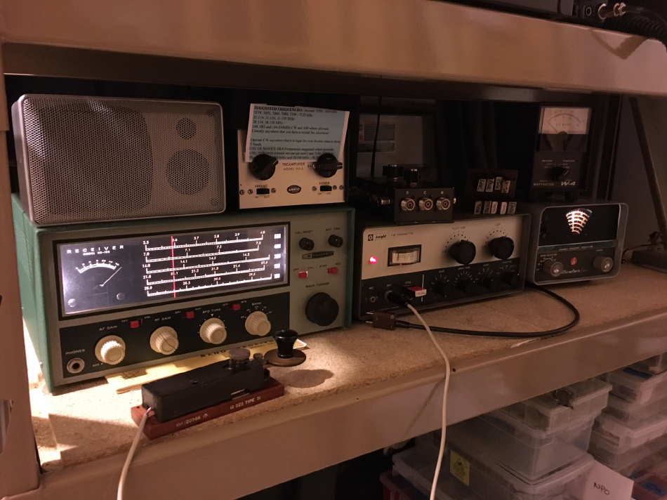
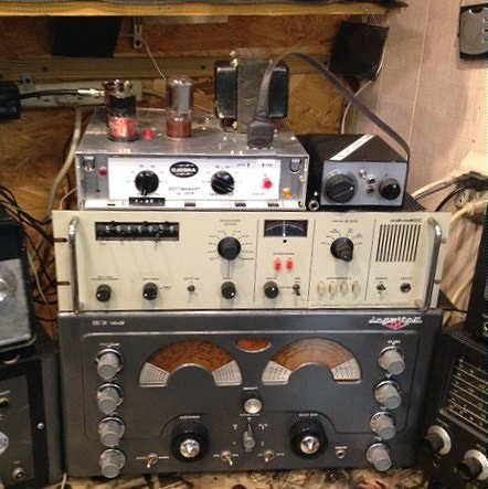
Scott, KA9P's 80m T-60 signal sounded as sweet as it looks in his 2018 setup, paired with his Heathkit HR-10B inhaler.
 |
| KA9P 2018 NRR station with RAF Vulcan bomber Type 51 hand pump |
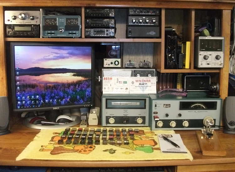
Right up there with the plethora of T-60s was the Drake 2NT, another great sounding radio and also my choice for this year's event. My summer refurbishing project, described here, proved a worthy companion, although my much-treasured VF-1 VFO's short term drift probably had my 2NT getting red in the face whenever I took her off of crystal control to scurry around the band, seeking out the CQ'ers. I've had a love-hate relationship with the VF-1 ever since buying my first one back in '63!
 |
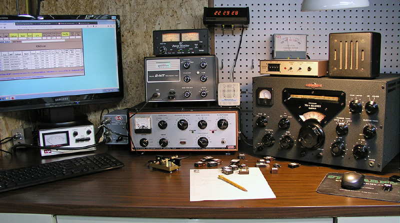
| VE7SL 2018 NRR with 2NT, VF-1 and my Original '63 Vibroplex |
Yet another 2NT packed a powerful punch from West Virginia, keyed by Dave, W3NP, when we exchanged 579 reports on 40m, 45 minutes before sunset.
 |
| W3NP - 2018 NRR setup |
I made three contacts on 15m this year: W5IQS in Texas, K2YWE in Maryland and WN4NRR in Florida, whose S9 reply to my 'CQ NRR' just about took my head off ... what a nice surprise to hear the booming signal from Bry's 2NT powerhouse. Dan, K2YWE, was no slouch either, as his Globe Scout was music to my ears when his signal quickly rose out of the noise just long enough to make the coast-to-coast journey. If the predictions for future solar cycles become reality, there may be many more NRRs before we experience the magic of 15m once again.
 |
| K2YWE's Globe Scout and Adventurer were worked on all three bands! |
My NRR exchanges with George, N3GJ (KA3JWJ) in Pennsylvania, truly demonstrated just how well the low bands were performing. More than an hour before my local sunset, I responded to his 569 40m 'CQ NRR' only to learn that his signal, now reaching a solid 579, was coming from an original Ameco AC-1! This one-tube crystal-controlled power oscillator has, over the years, reached Holy Grail status among many amateurs. Originals are guarded like precious jewels and handed down from father to son ... or in George's case, from uncle to nephew!
 |
| N3GJ and his all powerful original AC-1 |
Heathkits were plentiful too, with the DX-60 seeming to be the rig of choice, often paired with the matching HG-10 VFO. Both Mark, VA7MM and Gary, W8PU, packed a wallop with these fine examples.
 |
| VA7MM - 2018 NRR set-up |
 |
| W8PU - 2018 NRR set-up |
But it wasn't just DX-60s representing Benton Harbor engineering in the NRR. All of these neat old Heaths made it out to the west coast, sometimes on both 40 and 80. KN8RHM's (Rick) HW-16 made it here on 40m with a solid signal almost every night, while KE4OH (Steve) sported a modernized DX-20 in the form of Heath's HX-11. Steve even received the highly-treasured 'OO' report for his NRR chirp ... good job!
 |
| KN8RHM - HW-16 NRR set-up |
 |
| KE4OH - HX-11 NRR station |
 |
| N3PDT - DX-40 NRR transmitter |
Rich, WN7NRR / AG5M operating in nearby Washington state put some of his 44 crystals to work with his HW-16 ... that's some collection!
 |
| WN7NRR - HW-16 NTT set-up |
Howie, WB2AWQ in Reno, was using his homebrew pair of 807s, driven with a Millen 90700 swing-arm VFO from 1945. Most shacks worldwide, including the Novices, found plenty of use for the 807 as they were dirt-cheap in the post war surplus market. The filament has a beautiful illumination and if a bit gassy as most are by now, emit a wonderous blue glow with each press of the key.
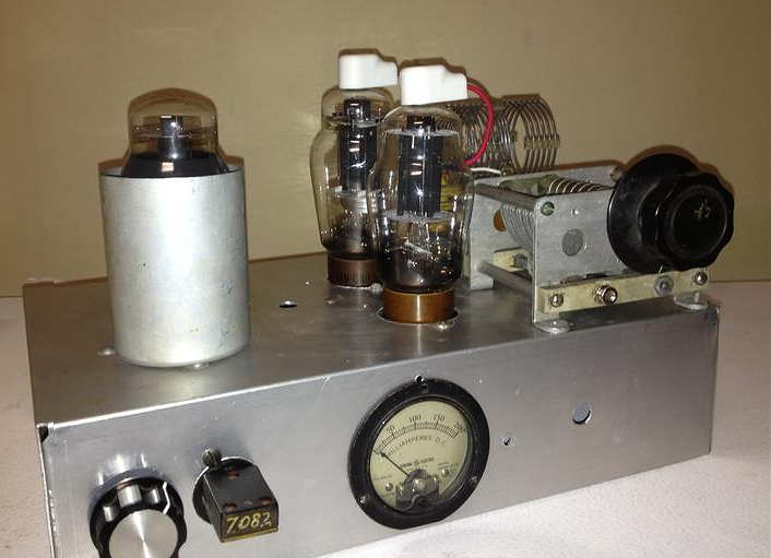 |
| WB2AWQ - 807s |
 |
| Millen VFO from 1945 at WB2AWQ |
 |
| KD7JG's 1625 NRR mainstay |
 |
| K4IBZ's 10 watter |
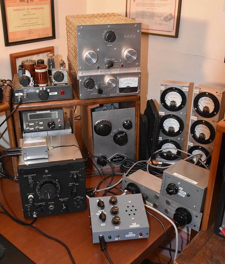 |
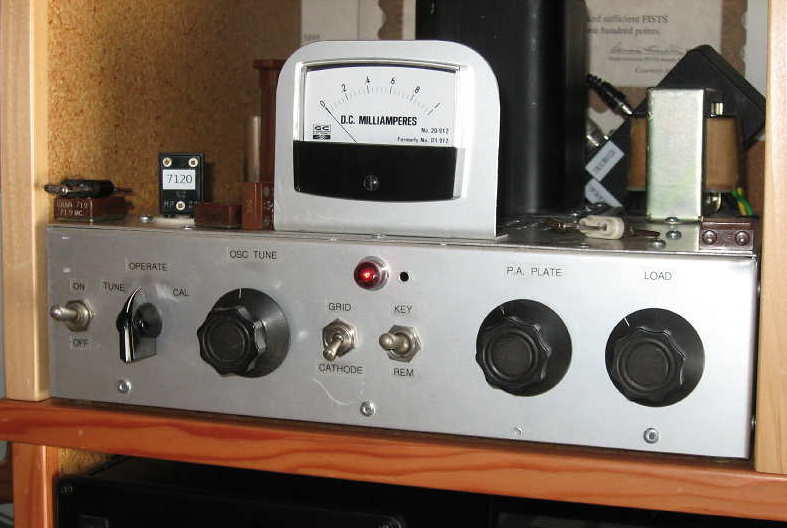
| AA8V's homebrew NRR stack |
 |
| VE3BDV / VE3AWA - 50C5 Bare - Essentials power oscillator |
I finished up the NRR with 123 contacts, a lot better than last year's event when I was running the Longfeller at 5 watts.
If you think that you might enjoy participating in the next event then now is the time to start preparing ... just 353 more sleeps until the 2019 NRR begins!!
The “BK 1929 QSO Party” From BC
 With this being my final blogspot of 2017, let me take this opportunity to wish all readers and radio friends season's greetings and good health and happiness in the coming new year. It's hard to believe that this is blog posting #470, having started blogging in the spring of 2014 ... how time flies when you're having fun. It flies even quicker when your both old and having fun at the same time!
The AWA's annual premier operating event, the "Bruce Kelley 1929 QSO Party", affectionately known as the "BK", has once again come and gone and some have already begun the countdown to next year's fun!
The hoped-for good conditions, not seen in the past few years, almost became a reality as it wasn't a complete washout like last year's event. Spread over two consecutive Saturday evenings, the best conditions were on the second night, but with just a few east coast stations making it into the log. Several of the 'eastern regulars' were just never heard here, as the band was not quite up to par ... maybe next year will see a return to the great low band conditions of the past.
As usual, I began on 40m, shortly after the BK start at around 1500 local time, and a good hour and a half before local sunset. Usually, 40m isn't too productive until closer to sunset and then, only briefly, as eastern stations have usually moved down to 80m just as the band opens up out here. Contacts with KØPK (MN) and K4JYS (KY) were followed by exchanges with locals VE7BDQ (John) and new BK'er VE7CNF (Toby).
As always, K4JYS's 1929 designed Hartley oscillator using a 210 at 20W input, made it up to this region consistently and was 559 with over an hour of daylight remaining.
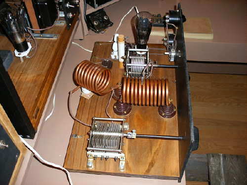 |
| K4JYS's 210 Hartley |
John and Toby both chose to build relatively rare 1929 designed Colpitts oscillators and were both exceptionally strong here.
 |
| VE7BDQ's Colpitts 45s |
 |
| VE7CNF's Colpitts 45s |
Here is a recording of VE7CNF's Colpitts on 80m thanks to Mark, VA7MM.
KK7UV, Steve in Montana, called in next, using his painstakingly restored REL MOPA (Master Oscillator Power Amplifier). His 5W input was a solid S7 here.
 |
| KK7UV's REL |
Moving down to 80m just after 1700 local time, netted contacts with WB9WHG (WI), KØSM (NY), W2ICE (NY), WA9WFA (MN) and W8KGI (NM) all before dinner hour.
I think Scott (WA9WFA) may be the only other Colpitts user and was a solid 569 here using his pair of 10s at 20W input.
 |
| WA9WFA's Colpitts '10s |
The band slowly deteriorated later in the evening but not before working N4GJV (NC) on his 3W Hartley oscillator and then finishing with back to back contacts with KØPK and KØKP, both in MN.
 |
| KØKP's Hartley '10 |
Weekend two started again in daylight on 40m, with the 25W Hartley signal of W2AN in New York booming into Mayne Island at 589! Truly remarkable with sunset being over 30 minutes away. What looked to be a really good night shaping up turned out to be disappointing once again ... but for a few strong 'spotlight' openings to the east, most east coast signals evaded me once again.
 |
| W2AN's Hartley 203A |
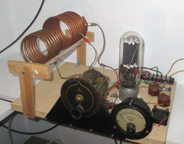
Back on 80 right at sunset brought W2AN (NY) once again followed by WØNYQ (MN) with his 4W TNT doing a nice job at 569.
 |
| WØNYQ's 4W TNT with a 245 |
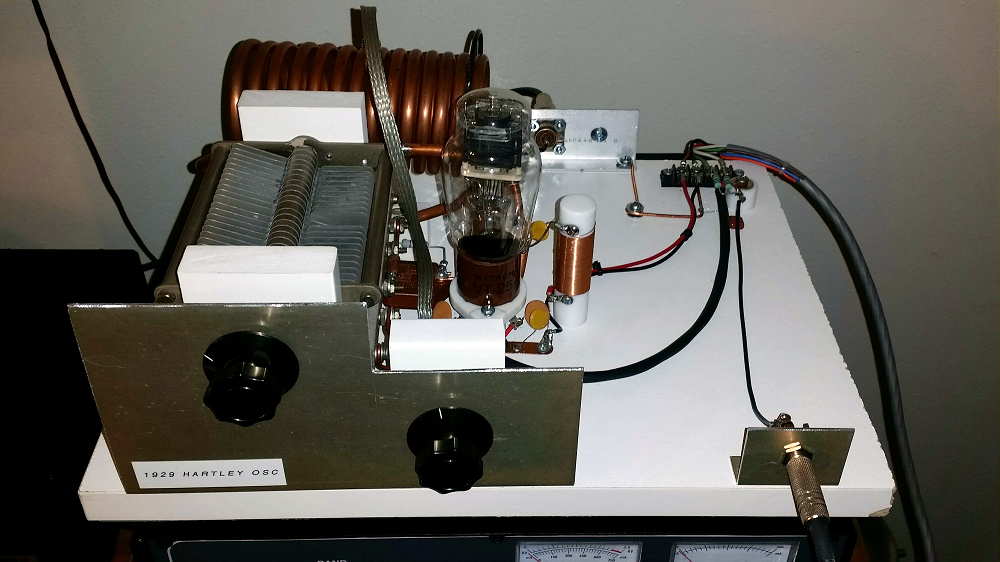
80m contacts were completed with N8YE (OH), NO3M (PA), W3GMS (PA) and the highlight of the evening, N2OUV, Joe in NY, running his 10W '29 Hartley and peaking 579 on the transcontinental path. I rarely work Joe but when I do it's always a delight as it was his YouTube video that originally inspired me to become a '29 builder and participant!
 |
| N2OUV's 211 Hartley |
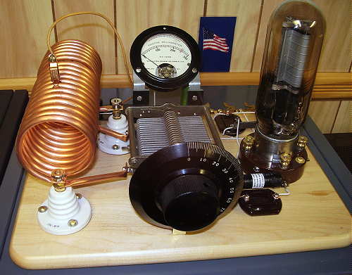
Hats off as well to Joe, W3GMS in PA whose rare original 18W TNT was putting an impressively solid signal into the west coast for over an hour ... he must have a great antenna.
 |
| W3GMS's Original '29 210 TNT |
Once again, I used my homebrew MOPA using type '10s for all contacts but I could have just as readily used my Hull Hartley or TNT as there was absolutely no wind on either weekend ... a very rare happening here on the ocean!
 |
| VE7SL's '10 MOPA |
One great positive was the appearance of several newcomers to the '29 Party, which seems to be growing in popularity each year. There is still a lot of interest in '29-style construction it would seem and if this is something that you might like to try for next year's event, here are some helpful guidelines from some of my previous blogs to help get those homebrew juices flowing. It's never too early to warm-up that soldering iron!
There is also some hands-on '29-style building info on my website that can be reached here.
While you are at it, don't forget to sign onto the AWAGroup of '29 Builders as there is plenty of help, discussion and good advice waiting for you there.

Hopefully we will see YOU and your new '29 transmitter next year along with those expected great band conditions!
The FA-VA4 Vector Antenna Analyzer (LF-100MHz)

For some time I had been considering the purchase of the MFJ259 antenna analyzer but after a little online sleuthing, came across this little beauty, the FA-VA4 Antenna Analyzer by Funk Amateur in Germany and available through their Box73 website here.
I liked the fact that the cost of the analyzer was about half that of anything else comparable ($140 US including shipping) and that it covered the new 2200 / 630m bands!
I think many amateurs planning on building a system for either of these new bands will find the very affordable FA-VA4 a handy piece of equipment when it comes to working on their LF / MF antenna since most available SWR meters do not cover these frequencies accurately.
Delivery time was fast and everything was very well packaged. The FA-VA4 comes in partial kit form and requires only a short amount of time to put together.
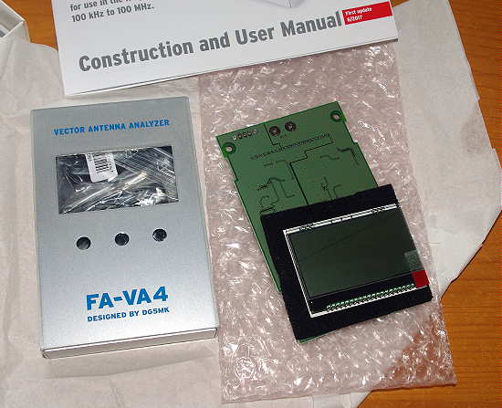
The necessary assembly consists of soldering pin strip connectors, switches, AA cell holders, and the BNC connector. All of the tricky SMD components have been pre-mounted ... total assembly time was less than 60 minutes and everything fired-up nicely, without problems, thanks to the well written instruction / user manual.

Included with the kit are three BNC connectors needed to calibrate the instrument for the highest accuracy. These consist of a 'Shorted' connector, an 'Open' connector and a 50 ohm 'Load' connector (SOL). A simple three-part calibration procedure for all frequencies takes about 15 minute to complete, while the instrument calibrates itself as it scans through all frequency ranges with each connector plugged into the output. Once this task is completed, the analyzer is ready for use.

If you're like me, I think the main use will be to check out and tweak some of your HF antennas using the SWR or Z sweep function. This allows you to set a desired 'center' frequency along with a + / - sweep range and have the display draw a nice plot of your system.
Had my 630m antenna not already been tuned and matched, I would have found the analyzer to be a great help but, thanks to my 'scopematch', that antenna has already been optimised.
All menu features and data entry is via three momentary-contact push switches. Although this might initially seem awkward, it is not, and operation is pretty intuitive.
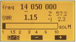
The main modes of operation are:
Single Frequency SWR Measurement
 |
| courtesy: http://www.box73.com/product/5 |
Single Frequency Impedance Measurement
 |
| courtesy: http://www.box73.com/product/5 |
Single SWR Measurement Run
 |
| courtesy: http://www.box73.com/product/5 |
Single Run For Impedance Measurement (Resistance and Reactance)
 |
| courtesy: http://www.box73.com/product/5 |
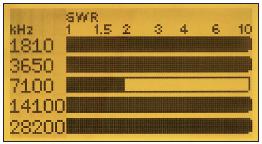
SWR Measurement On Five Frequencies (5 Band Measurement)
 |
| courtesy: http://www.box73.com/product/5 |
As well, all of the above can be viewed in a continuous 'cycle' mode, as inputs are changed and all screens can be saved for future reference.
Additional capabilities include use in an HF Signal Generator Mode (~ 1V square wave @50 ohms), the ability to measure C and L at a given frequency, as a 'dip meter' and to measure cable resonances and determine lengths.
The complete manual may also be downloaded from their website here.
I will soon put all of my antennas to the test and see what work might need to be done to optimize them, particularly my HF half slopers, which, in spite of their great performance, have always proven a bit of a mystery when it comes to pruning them to resonance ... I rather suspect that the sloping wires are more of an impedance tuning stub than a radiator and that most radiation comes from the vertical support tower, not the sloping wire.
All-in-all, the FA-VA4 appears to offer very good value for the money and is a well built, quality test instrument. I think it will become a popular choice among hams, especially those on LF / MF. The only thing different that I would have liked, would be to have a UHF (SO 239) connector rather than a BNC on the output, since most amateurs are using these on their HF systems ... or, the inclusion of a BNC-to-UHF adapter.
If you already use this device, please feel free to add your comments below!


