Posts Tagged ‘homebrew’
 Hamvention Is Here – ETH069
With Hamvention already on top of us, I figured I’d throw my two cents worth into the mix with everybody else’s. In this episode of the Everything Ham Radio Podcast, we talk about some of the interesting things that are going to be going on at this years Hamvention at it’s new location in Xenia, OH.
DARA teamed up with The Miami Valley Mesh Alliance (MVMA) to setup a Mesh network on channel -2 at 10 MHz bandwidth. The SSID is AREDN-10-v3.
We talk about all of my fellow podcasters/youtubers that are there and what they have going on and where they are at.
Lastly, we discussed some of the interesting forum topics that are going on during the weekend. To listen to the episode as well as check out all the links and further information on the topic, check out the show notes at:
The G3XBM Experimental Blogs
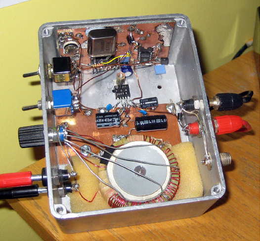 |
| G3XBM's 5W Earth-Mode Tx (courtesy: G3XBM) |
My interest of late has been piqued by the ongoing VLF experimental work by several European amateurs.
Recalling that Roger, G3XBM, did some VLF experimenting a few years ago, I have been reviewing some of the excellent hands-on information gathered and published in his ham radio blog and to some of his other VLF pages.
It's not the first time that I have found project-inspiring reading within Roger's blogs. They really are a treasure-trove of useful information, construction notes and accumulated test data gathered from his methodical approach to so many interesting topics ... experimental amateur radio at its very best.
A few years ago I was immediately hooked by his experimental lightwave work, both line-of-sight and clear-air / cloudbounce scatter ... so much so that I also became involved in some lightwave work with other locals who were also inspired by Roger's information, culminating in our own West Coast Lightwave Adventure.
Roger's VLF experiments are also proving hard to resist, especially those of the earth-mode type and I may find myself falling victim to his detailed Sub 9kHz Amateur Radio pages and the Earth Mode pages in particular.
It seems that most amateur VLF work is being done in the vicinity of 8kHz since this part of the frequency spectrum is unassigned. I gather that one can conduct earth-mode tests in any portion of the VLF spectrum since no signal is being 'radiated' as is typically done via antennas. Further investigation remains to see if I need a 'developmental licence' to conduct some radiated (non-earth-mode) experiments in the 8kHz range as well.
Getting a VLF signal from here on Mayne Island across Georgia Strait via earth-mode or via conventional methods would make an interesting challenge and would certainly result in some new homebrewing opportunities.
 |
| courtesy: https://www.google.ca/maps |
Here on the island, I often hear audio associated with the container terminal and ship-loading operations near Tsawwassen, directly across the strait from here. I feel that this may be aided somewhat by the solid sandstone of the island being directly connected to the other side, so perhaps an earth-mode system utilizing the ocean as one-leg of a buried loop might be an interesting experiment to tackle ... or groundwave transmissions across the ocean via an antenna, to the other side, providing I could find someone to listen.
I see just two Canadian amateurs experimenting on VLF ... VO1NA (Joe) and VA3VVV (John) near Toronto. Any VE3's in the area who are interested in VLF may wish to contact John and exchange notes. He has a Facebook page showing his VLF setup. Interestingly, Joe's 30W VLF signal on 8.270 kHz has just crossed the Atlantic! Joe is documenting his VLF experiments here.
All of G3XBM's VLF blogs can be downloaded for reading or for printing via this link. Similarly, his lightwave experiments can all be found here ... both links will yield several pages of material if you click on the 'Older Posts' link at the bottom of each page.
The best way to follow these is chronologically which requires going all the way to the end of the final 'OlderPost' link and follow along with Roger as he gradually develops, evaluates and improves the gear that he needs to make progress. This is fascinating reading.
But be suitably warned ... you may readily fall victim to his experimental work as well and suddenly find yourself with another exciting project!
The G3XBM Experimental Blogs
|
| G3XBM's 5W Earth-Mode Tx (courtesy: G3XBM) |
My interest of late has been piqued by the ongoing VLF experimental work by several European amateurs.
Recalling that Roger, G3XBM, did some VLF experimenting a few years ago, I have been reviewing some of the excellent hands-on information gathered and published in his ham radio blog and to some of his other VLF pages.
It's not the first time that I have found project-inspiring reading within Roger's blogs. They really are a treasure-trove of useful information, construction notes and accumulated test data gathered from his methodical approach to so many interesting topics ... experimental amateur radio at its very best.
A few years ago I was immediately hooked by his experimental lightwave work, both line-of-sight and clear-air / cloudbounce scatter ... so much so that I also became involved in some lightwave work with other locals who were also inspired by Roger's information, culminating in our own West Coast Lightwave Adventure.
Roger's VLF experiments are also proving hard to resist, especially those of the earth-mode type and I may find myself falling victim to his detailed Sub 9kHz Amateur Radio pages and the Earth Mode pages in particular.
It seems that most amateur VLF work is being done in the vicinity of 8kHz since this part of the frequency spectrum is unassigned. I gather that one can conduct earth-mode tests in any portion of the VLF spectrum since no signal is being 'radiated' as is typically done via antennas. Further investigation remains to see if I need a 'developmental licence' to conduct some radiated (non-earth-mode) experiments in the 8kHz range as well.
Getting a VLF signal from here on Mayne Island across Georgia Strait via earth-mode or via conventional methods would make an interesting challenge and would certainly result in some new homebrewing opportunities.
|
| courtesy: https://www.google.ca/maps |
Here on the island, I often hear audio associated with the container terminal and ship-loading operations near Tsawwassen, directly across the strait from here. I feel that this may be aided somewhat by the solid sandstone of the island being directly connected to the other side, so perhaps an earth-mode system utilizing the ocean as one-leg of a buried loop might be an interesting experiment to tackle ... or groundwave transmissions across the ocean via an antenna, to the other side, providing I could find someone to listen.
I see just two Canadian amateurs experimenting on VLF ... VO1NA (Joe) and VA3VVV (John) near Toronto. Any VE3's in the area who are interested in VLF may wish to contact John and exchange notes. He has a Facebook page showing his VLF setup. Interestingly, Joe's 30W VLF signal on 8.270 kHz has just crossed the Atlantic! Joe is documenting his VLF experiments here.
All of G3XBM's VLF blogs can be downloaded for reading or for printing via this link. Similarly, his lightwave experiments can all be found here ... both links will yield several pages of material if you click on the 'Older Posts' link at the bottom of each page.
The best way to follow these is chronologically which requires going all the way to the end of the final 'OlderPost' link and follow along with Roger as he gradually develops, evaluates and improves the gear that he needs to make progress. This is fascinating reading.
But be suitably warned ... you may readily fall victim to his experimental work as well and suddenly find yourself with another exciting project!
LF / MF Antenna Planning
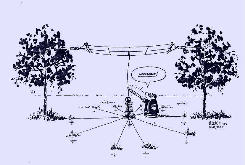 |
| courtesy: Chuck Roblin |
For U.S. amateurs, the 2200 and 630m bands will soon be a reality and I have no doubt that there will be an accompanying surge in interest among large numbers of homebrewers and low band diehards.
It should be an exciting time as new stations gradually start to populate the band from coast to coast.
High on the 'to do' list will be the planning and building (or modifying) of a suitable antenna system for the band(s) of choice. For most, this will be new territory, but the reality is that there has been a long tradition of operation in the LF and MF bands in the U.S. for many years ... all under the Part 15 'Lowfer' and 'Medfer' service.
Although activity in this category has fallen off over the years due to the availability of the much less-restrictive Part 5 experimental licences, there is still a great legacy of literature and information left behind that is every bit as useful today as it was back in the golden years of Lowfer operations.
Here is one such document from Stephen McGreevy's Natural ELF-VLF Radio website that many newcomers to these bands may find very helpful as it covers a wide variety of LF antenna-related basics in a down-to-earth manner.
An even more detailed treatise on virtually all aspects of LF and MF antenna topics is that found on Rik, ON7YD's website. His antenna pages can be found here. Although originally developed for the 2200m band, the principles are equally applicable to 630m as well.
Hopefully both of these sources will help you decide how to get a working antenna system up and running on the new bands. And as always, much help is available via the Internet on the Lowfer Reflector, the RSGB LF reflector or on the 600MRG Reflector.
LF / MF Antenna Planning
|
| courtesy: Chuck Roblin |
For U.S. amateurs, the 2200 and 630m bands will soon be a reality and I have no doubt that there will be an accompanying surge in interest among large numbers of homebrewers and low band diehards.
It should be an exciting time as new stations gradually start to populate the band from coast to coast.
High on the 'to do' list will be the planning and building (or modifying) of a suitable antenna system for the band(s) of choice. For most, this will be new territory, but the reality is that there has been a long tradition of operation in the LF and MF bands in the U.S. for many years ... all under the Part 15 'Lowfer' and 'Medfer' service.
Although activity in this category has fallen off over the years due to the availability of the much less-restrictive Part 5 experimental licences, there is still a great legacy of literature and information left behind that is every bit as useful today as it was back in the golden years of Lowfer operations.
Here is one such document from Stephen McGreevy's Natural ELF-VLF Radio website that many newcomers to these bands may find very helpful as it covers a wide variety of LF antenna-related basics in a down-to-earth manner.
An even more detailed treatise on virtually all aspects of LF and MF antenna topics is that found on Rik, ON7YD's website. His antenna pages can be found here. Although originally developed for the 2200m band, the principles are equally applicable to 630m as well.
Hopefully both of these sources will help you decide how to get a working antenna system up and running on the new bands. And as always, much help is available via the Internet on the Lowfer Reflector, the RSGB LF reflector or on the 600MRG Reflector.
The Artwork Of DK1IS
Recent discussion on the RSGB LF Group reflector about high-powered LF / MF amplifiers brought an interesting response from Tom, DK1IS, and his unique solution.
It's no secret that a Class D / E amplifier using switching MOSFETs is a popular and reasonably inexpensive method of generating some serious RF on the LF and MF bands. Equally well-known is their propensity to gobble-up FETs should the amplifiers encounter much reactance in their output load. Most builders include some form of protection for sudden over-current or unwanted SWR excursions which will shut down the amplifier before any FETs can self-destruct. Those that don't usually end up replacing FETs.
I would venture to guess that over 90% of the transmitters now being employed on LF or MF are using switching MOSFETs in a Class D / E design but there are some amateurs using vacuum tubes to do their heavy-lifting ... and with good results.
DK1IS's beautiful homebrew amplifier is shown below. Tom provided the following description:
Hi Wolf and group,
nice to hear that someone else is thinking about this approach! I´m
content with my homemade tube PA for LF and MF which has provided
reliable service since nearly 4 years now. Only some thoughts about this
concept - I hope not to bore all those hams who are happy with their
semiconductor PAs:
Years ago I had a MOSFET PA for LF, Class B push-pull with 250 W RF. It
worked well at constant conditions, but when I had to retune the antenna
due to larger QSY or made antenna experiments there always was the
danger of blowing up these nervous semiconductors. After 4 or 5 times
changing the MOSFETS I decided to build a new PA - with tubes! Looking a
little bit anachronistic this PA is absolutely good-natured. Designed for
broadband service on LF and MF it makes no problems when changing the
antenna coarse tuning from one band to the other even when the fine
tuning isn't done yet. With my former MOSFET-PA this would have been
impossible.
I wanted to have a linear PA - this usually means class B. You have to
decide between narrow band and broad band (like an audio-amp) design.
For narrow band you can use a single-ended PA but you have to add a
resonance circuit. For broad band you should use a push-pull PA and have
to build a suitable output transformer. I opted for broad band design
because it is usable for LF and MF without changes at the PA. With this
design and sin-driving I reach a total harmonic distortion of about 5 %
at 700 W RF on a pure resistive dummy load. With the usual narrow,
narrow band antennas on LF and MF you don´t need additional filters!
Concerning the tubes: If you take the common TX tubes with plate
voltages of several kV all output circuits have rather high impedances,
that means large coils for the resonance circuits resp. large
transformer windings and very high voltages - potentially a construction
problem. This led me to the choice of 2x 4x PL519 in push-pull, a rugged
colour TV line output tube with low plate voltage and high plate
current. In this way I came down to a plate-to-plate resistance of about
1 kOhm at 600 V DC plate voltage, where you easily can build a ferrite
broad band output transformer down to 50 Ohms. A disadvantage of this
concept is that you have to give individual bias to each tube, that
means for the first start-up you have to align 8 potentiometers
carefully to nearly equal cathode currents for all the tubes. But
according to my experience this alignment remains stable over a long
time. I have inserted 1-Ohm-resistors in each cathode line and have
brought the voltage drops to 8 cinch connectors, where I can monitor the
DC component (with external filtering) as well as the real time current.
With 4 tubes in parallel per branch of course you have to take care for
self oscillations. The extensive use of bypass capacitors, ferrite beads
and parasitic chokes in the plate lines is mandatory as well as good
grounding concepts are. The tubes don´t pull control grid current (this
would even be true in class C!) but you need 3 or 4 W RF input power due
to all the ohmic loads at the tube´s control grids caused by the
individual bias paths. On the other hand this certainly helps to avoid
oscillations. You can see some pictures of this PA at https://www.qrz.com/db/DK1IS
By the way: why not to try these tubes at class D? With DC plate
voltages of perhaps 1200 V you should get a nice QRO-PA ...
Wolf, you are right: building such a PA from scratch is a time consuming
enterprise. I didn´t count the working hours but according to my lab log
the whole project took about 9 months - an adequate time for a new baby!
It was a great experience anyway.
Good luck and 73,
Tom, DK1IS
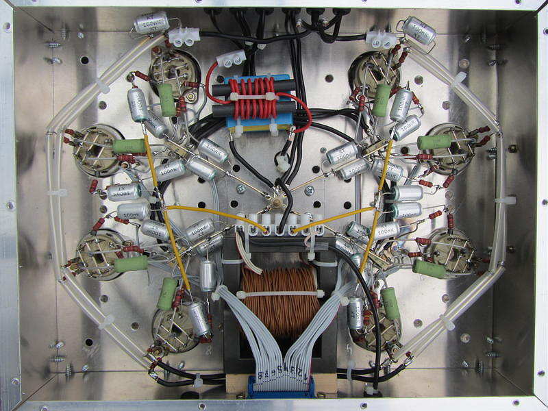
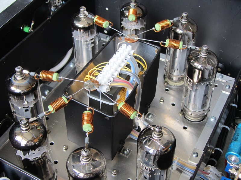 | ||
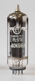
| 2x 4x PL519 Push-Pull |
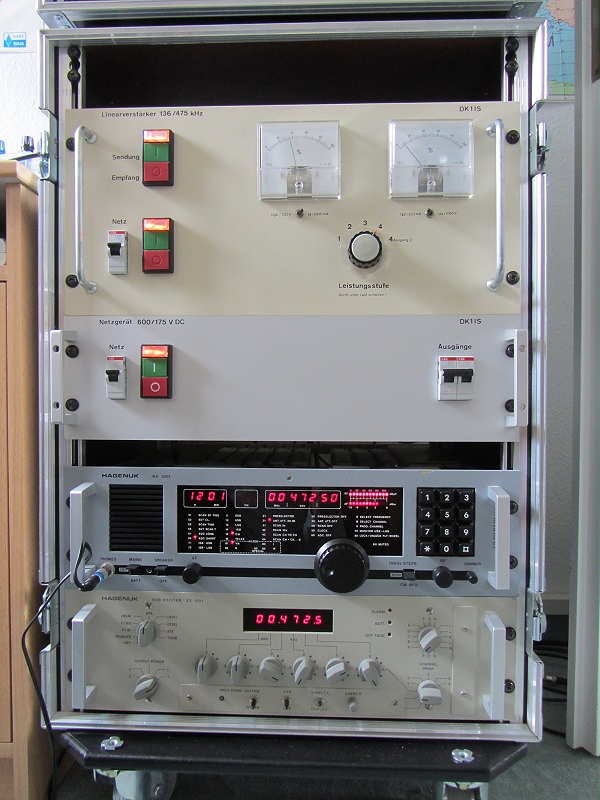 |
| TX, power supply, RX, exciter |
DK1IS has provided an inspiring example of what can be done using vacuum tubes ... they certainly should not be discounted as a viable method of generating your hard-earned LF / MF ERP.
The Artwork Of DK1IS
Recent discussion on the RSGB LF Group reflector about high-powered LF / MF amplifiers brought an interesting response from Tom, DK1IS, and his unique solution.
It's no secret that a Class D / E amplifier using switching MOSFETs is a popular and reasonably inexpensive method of generating some serious RF on the LF and MF bands. Equally well-known is their propensity to gobble-up FETs should the amplifiers encounter much reactance in their output load. Most builders include some form of protection for sudden over-current or unwanted SWR excursions which will shut down the amplifier before any FETs can self-destruct. Those that don't usually end up replacing FETs.
I would venture to guess that over 90% of the transmitters now being employed on LF or MF are using switching MOSFETs in a Class D / E design but there are some amateurs using vacuum tubes to do their heavy-lifting ... and with good results.
DK1IS's beautiful homebrew amplifier is shown below. Tom provided the following description:
Hi Wolf and group,
nice to hear that someone else is thinking about this approach! I´m
content with my homemade tube PA for LF and MF which has provided
reliable service since nearly 4 years now. Only some thoughts about this
concept - I hope not to bore all those hams who are happy with their
semiconductor PAs:
Years ago I had a MOSFET PA for LF, Class B push-pull with 250 W RF. It
worked well at constant conditions, but when I had to retune the antenna
due to larger QSY or made antenna experiments there always was the
danger of blowing up these nervous semiconductors. After 4 or 5 times
changing the MOSFETS I decided to build a new PA - with tubes! Looking a
little bit anachronistic this PA is absolutely good-natured. Designed for
broadband service on LF and MF it makes no problems when changing the
antenna coarse tuning from one band to the other even when the fine
tuning isn't done yet. With my former MOSFET-PA this would have been
impossible.
I wanted to have a linear PA - this usually means class B. You have to
decide between narrow band and broad band (like an audio-amp) design.
For narrow band you can use a single-ended PA but you have to add a
resonance circuit. For broad band you should use a push-pull PA and have
to build a suitable output transformer. I opted for broad band design
because it is usable for LF and MF without changes at the PA. With this
design and sin-driving I reach a total harmonic distortion of about 5 %
at 700 W RF on a pure resistive dummy load. With the usual narrow,
narrow band antennas on LF and MF you don´t need additional filters!
Concerning the tubes: If you take the common TX tubes with plate
voltages of several kV all output circuits have rather high impedances,
that means large coils for the resonance circuits resp. large
transformer windings and very high voltages - potentially a construction
problem. This led me to the choice of 2x 4x PL519 in push-pull, a rugged
colour TV line output tube with low plate voltage and high plate
current. In this way I came down to a plate-to-plate resistance of about
1 kOhm at 600 V DC plate voltage, where you easily can build a ferrite
broad band output transformer down to 50 Ohms. A disadvantage of this
concept is that you have to give individual bias to each tube, that
means for the first start-up you have to align 8 potentiometers
carefully to nearly equal cathode currents for all the tubes. But
according to my experience this alignment remains stable over a long
time. I have inserted 1-Ohm-resistors in each cathode line and have
brought the voltage drops to 8 cinch connectors, where I can monitor the
DC component (with external filtering) as well as the real time current.
With 4 tubes in parallel per branch of course you have to take care for
self oscillations. The extensive use of bypass capacitors, ferrite beads
and parasitic chokes in the plate lines is mandatory as well as good
grounding concepts are. The tubes don´t pull control grid current (this
would even be true in class C!) but you need 3 or 4 W RF input power due
to all the ohmic loads at the tube´s control grids caused by the
individual bias paths. On the other hand this certainly helps to avoid
oscillations. You can see some pictures of this PA at https://www.qrz.com/db/DK1IS
By the way: why not to try these tubes at class D? With DC plate
voltages of perhaps 1200 V you should get a nice QRO-PA ...
Wolf, you are right: building such a PA from scratch is a time consuming
enterprise. I didn´t count the working hours but according to my lab log
the whole project took about 9 months - an adequate time for a new baby!
It was a great experience anyway.
Good luck and 73,
Tom, DK1IS
| ||
| 2x 4x PL519 Push-Pull |
|
| TX, power supply, RX, exciter |
DK1IS has provided an inspiring example of what can be done using vacuum tubes ... they certainly should not be discounted as a viable method of generating your hard-earned LF / MF ERP.


