Posts Tagged ‘homebrew’
 The Everlasting Ameco AC-1
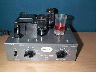 |
| courtesy: WB1GFH's AC-1 site |
I continue to be amazed at the high prices being paid on E-Bay for original Ameco AC-1 transmitters but perhaps I shouldn't ... they've been doing this for several years now.
Few radios that I can think of have elevated themselves to the cult status enjoyed by the AC-1, but the 3-tube Knight Ocean Hopper regen also comes to mind. Both radios typically reach $100- $200 on auction, with some going for much more. There were plenty of AC-1's sold and built over the years so it's not as if they're rare.
They seem to pop up frequently on E-Bay and the auctions are usually very spirited. I see a nice looking one at present, with 23 bids so far and now at $150! I guess the timing is just about right, with a large supply of now-retired ex-50's Novices who once owned an AC-1, looking to turn back the clock and recreate their early radio experience.
As transmitters go, they don't come much simpler, but the well-designed and smartly marketed radio made it extremely popular among the vast numbers of newly-licenced teenaged Novices who likely didn't have much spare change ... the first ones hit the market in the late 50's, right in time for the strongest solar cycle on record, selling for $14.95 in kit form. AC-1's continued to be sold into the early 70's with the price rising to around $25 ... a nice long run for most ham gear. I may be wrong but I don't think they were ever available in anything other than kit form.
Here is what the kit looked like upon arrival ... this one still NIB in 2012!
 |
| courtesy: http://www.wa0itp.com/ac-1.html |
There is also a large builder's interest in making AC-1 'clones' along with a dedicated Yahoo Group for additional support. Several years go I decided to scratch-build my own clone and found that I had everything needed except for the gray hammertone spray paint. Although most AC-1's used black chicken head knobs, some early models used maroon knobs so I decided to go with a red slide switch and red chicken head knobs on my reproduction. The important decal was available at the time from the Yahoo group but I see them now being sold by Radio Daze, for those that may want to try their hand at building a clone themselves.
The AC-1 uses the inexpensive 6V6 elevated from AF to RF duty, in a crystal-friendly Colpitts crystal oscillator. The only departure from the norm is the output circuit. Most inexpensive one-tubers end up with a link-coupled output but the AC-1 uses the more versatile pi-network ... something that no doubt added to its production costs but produced a transmitter able to load a wider range of antenna impedances while providing superior harmonic attenuation, both important in a beginner's rig.
My clone puts out 8 watts on 80m and 7 watts on 40m. Although never intended, doubling to 20m sees a large drop in efficiency, with output power dropping to 2 watts. Swapping to a 6L6 yields an extra couple of watts. Not enough to be noticed at the other end except when doubling or tripling.
I haven't had my clone on the air for a few years and think it's time to spark it up once again for some summertime fun on 40m CW. It would be great to work another clone or even a real AC-1 if you have one, but any contacts will be exciting if you would like to try.
I'll be hanging around 7118 kHz or down near 7040 and ... I won't be loud!
 EME In The ’80s
 |
| VE7SL - my original 2m EME antenna. |
Unlike today's widespread JT65B usage on eme, where signals can be many db into the noise and inaudible by ear, eme contacts could only be completed by actually copying signals that you could hear with your ears. This usually required big antennas and lots of power.
After a year and a half of evening work in my basement shop, my system was pretty much ready to go. I built a kilowatt amplifier, from the ARRL's VHF Handbook, along with its plate and screen power supplies.
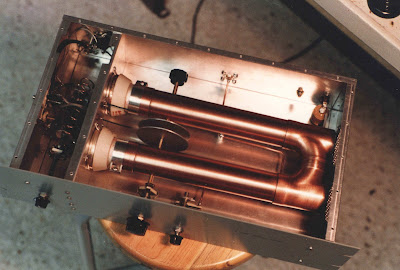 |
| 2m 'Plumbers Delight' handbook amp. |
My antennas (see above), as well as the large H-frame support, were also built in the basement and used all scrap aluminum from one of the numerous scrap yards that were in Vancouver at the time. The system consisted of sixteen separate 6 element NBS-styled yagis, all phased. Many of the two-dozen plus N connectors were bought at Boeing Surplus near Seattle, another interesting source of parts, also now long gone. Keeping water out of the phasing lines and connectors was a real challenge here in the rain forest and if one connector was not done exactly right, would create a lot of headaches.
The antenna took up a large portion of my small, 33'-wide suburban backyard. Pointing was all done by hand, using homemade scales to indicate elevation and azimuth angles, so that it could be pointed accurately even on cloud covered days and nights. A hand-cranked boat winch took care of elevation. I had a switch-box full of surplus VHF relays out at the antenna that protected my JFET preamp and also allowed me to compare sky and sun noise against a 50 ohm load.
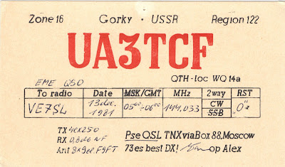
Over the course of a few years, the system was employed to work many Europeans as well as North American VEs' and Ws'. The one contact that stands out memorable for me, was with UA3TCF, east of Moscow. This was because I had to aim the array directly into my two-story house, located about 20' away! The moon was very low as well, so that not much elevation was required.
I eventually found that trying to hold down a full-time high school teaching job and running sked requests at 0300 were not very compatible! It also became a lot of work just to maintain the system properly. I had met and completed my original goals and it became time to move on.
Eventually the array was broken down into smaller sections and sold to local 2m guys, along with the amplifier ... but it was a huge learning experience for me and the fact that I survived building and playing with a 2,000 volt power supply, still scares the heck out of me!
 |
| Plate & screen supply for the 2m amp. |
 |
| The VHF rack with xvrtrs and amps 50mHz-432mHz. |
 |
| My gal Sal adorning the 2m tower on a snowy Sunday morning. |
 EME In The ’80s
 |
| VE7SL - my original 2m EME antenna. |
Unlike today's widespread JT65B usage on eme, where signals can be many db into the noise and inaudible by ear, eme contacts could only be completed by actually copying signals that you could hear with your ears. This usually required big antennas and lots of power.
After a year and a half of evening work in my basement shop, my system was pretty much ready to go. I built a kilowatt amplifier, from the ARRL's VHF Handbook, along with its plate and screen power supplies.
 |
| 2m 'Plumbers Delight' handbook amp. |
My antennas (see above), as well as the large H-frame support, were also built in the basement and used all scrap aluminum from one of the numerous scrap yards that were in Vancouver at the time. The system consisted of sixteen separate 6 element NBS-styled yagis, all phased. Many of the two-dozen plus N connectors were bought at Boeing Surplus near Seattle, another interesting source of parts, also now long gone. Keeping water out of the phasing lines and connectors was a real challenge here in the rain forest and if one connector was not done exactly right, would create a lot of headaches.
The antenna took up a large portion of my small, 33'-wide suburban backyard. Pointing was all done by hand, using homemade scales to indicate elevation and azimuth angles, so that it could be pointed accurately even on cloud covered days and nights. A hand-cranked boat winch took care of elevation. I had a switch-box full of surplus VHF relays out at the antenna that protected my JFET preamp and also allowed me to compare sky and sun noise against a 50 ohm load.
Over the course of a few years, the system was employed to work many Europeans as well as North American VEs' and Ws'. The one contact that stands out memorable for me, was with UA3TCF, east of Moscow. This was because I had to aim the array directly into my two-story house, located about 20' away! The moon was very low as well, so that not much elevation was required.
I eventually found that trying to hold down a full-time high school teaching job and running sked requests at 0300 were not very compatible! It also became a lot of work just to maintain the system properly. I had met and completed my original goals and it became time to move on.
Eventually the array was broken down into smaller sections and sold to local 2m guys, along with the amplifier ... but it was a huge learning experience for me and the fact that I survived building and playing with a 2,000 volt power supply, still scares the heck out of me!
 |
| Plate & screen supply for the 2m amp. |
 |
| The VHF rack with xvrtrs and amps 50mHz-432mHz. |
 |
| My gal Sal adorning the 2m tower on a snowy Sunday morning. |
 1929 QSO Party Weekends
This Saturday as well as the next will be the annual Bruce Kelley 1929 QSO Party, otherwise known as the '1929 BK'.
It's the once a year opportunity to celebrate the sounds of early amateur radio ... only transmitters that are 'era-appropriate' are allowed to be used. More specifically, transmitters must employ tubes that were available in 1929 or earlier, and transmitters must be self-excited. No crystals allowed! Crystals were new and largely unaffordable for most hams back in the depression days.
1929 marked a real turning point in amateur radio as governments finally cracked-down on things such as frequency stability, out of band operations and re-alignment of call districts. In short, hams were henceforth required to behave themselves and to clean up their signals and methods of operation.
 |
| courtesy: http://www.arrl.org/ |
If you tune across the CW bands during the next two Saturday nights, you will have the rare opportunity to hear exactly what the bands must have sounded like back in the early '30s'.
For the most part you will hear single tube Hartley, Colpitts or TNT oscillators with a few two-tube MOPAs' thrown in. Many of them will suffer the same problems encountered by the boys of '29 ... chirp, drift, buzzy notes and frequency instability from antennas swaying in the wind. The MOPAs' will sound much better but some surprisingly nice-sounding signals can be heard coming from properly tuned and optimised single-tube oscillators. I recall being blown away by the lovely sounding signal I heard from such a rig when first tuning into the BK activity several years ago, only to learn that it was a self-excited Hartley using 1/4" copper tubing for the oscillator tank circuit!
The '29 watering-hole on 80m will be around 3550-3580 kilocycles (be careful not to confuse this with kilohertz!) while the early afternoon to sunset 40m activity will be found from 7100-7125 kc. There may even be a few on the very low end of 160m, later on the first Saturday night only. Although many of these transmitter styles were used on 20m and higher, BK rule-makers have wisely decided not to inflict these sounds on the present populace as it would likely keep the 'Official Observer' guys busy for several days writing pink-slips.
You can learn more about amateur radio happenings leading up to and following the 1929 crackdown in my earlier series of 'Why '29' blogs here:
Part 2
Part 3
Part 4
Those wishing to put something together for next year's event can find everything needed here:
Building '29-Style - Part 1
Building '29-Style - Part 2
Unfortunately due to a number of coinciding events, I'll not be on-the-air for the event this year, the first one I've missed since getting in on the fun several years ago.
 More On The PAØRDT E-Probe
 |
| Courtesy: http://www.leeszuba.com/projects/ |
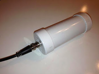
Another recent reflector question about noise mitigation for active e-probe antennas brought further incite from Roelof Bakker, PAØRDT.
I found particular interest in his method of determining if the noise is being picked up by the antenna or being introduced by the feedline. As well, Roelof suggests one of the most important aspects of homebrewing ... keeping detailed notes of all tests or changes. He also suggests maintaining a healthy outlook regarding noise and rather than getting discouraged, take on the challenge of overcoming it!
Hello all,
I have been dealing with this subject for more then 10 years now and
I am pleased to pass on what I did learn so far.
The first item to look at is noise pick up on the feed line. This
can be a coax cable or a CAT5/6/7 network cable. Looking for noise
pick up on the feed line should be done without the active antenna
connected. Otherwise everything should be the same as when using the
antenna.
Ideally the antenna should be replaced by a 50 ohm termination that
can handle the power that is supplied by the DC-power supply feeding
the antenna. However, this is not necessary to achieve good results.
I am fortunate to own a PERSEUS SDR, that besides an excellent
receiver is also a nice piece of test gear. For noise pick-up
measurements I use HF-Span that changes the PERSEUS into a 0-40 MHz
spectrum analyser with a noise floor of -112 dBm. For narrow band
measurements the PERSEUS is used with Linrad, which can provide
accurate results.
Whilst looking at noise pick-up on the cable, one can unplug all
suspect devices and check if the noise is still present.
The most effective measure is grounding the shield of the coax cable
at the bottom of the mast, but I had still noise ingress of about -
100 dBm around 15 MHz. This could be solved by moving the power
supply and interface of the antenna from the operating position to
the location of the cable entry to the house. This minimises the
length of cable inside the house before the a rf-isolating
transformer used in the interface.
It is mandatory to use a separate radio earth, isolated from the
mains earth. My PC is connected to a mains outlet with a mains earth
connection, but no other equipment in the shack is using the mains
earth. This works for me.
There is also a discussion about the use of a common mode choke
versus a rf-isolating transformer. I have tried both and they both
work. However a rf-isolating transformer is much easier (and
cheaper) to build than common mode chokes with a winding of coax
cable.
In this regard, I should mention a source of interference that is
easily overlooked: receivers. It is not uncommon to own more than
one receiver and it appears that the antenna port is often far from
clean. I am using four SDR's which are fed from a balanced Norton
amplifier / four port splitter and these produce noticeable noise.
Using four rf-isolating transformers at the outputs of the splitter
eliminated the noise. My mini-whip is feeding up to 8 receivers
(hardware) via amplifiers /splitters / rf-isolating transformers
without degrading the receiver noise floor by mutual noise ingress.
The last point is about masts. A metal mast will decrease the signal
level when the antenna is mounted close to it. A short PVC extension
mast will help. The reason I am using a non-conductive mast is a
practical one as cheap and sturdy stackable camouflage net mast
sections were and are still available in western Europe. These are
ideal for either testing antennas and for permanent installations.
Metal masts can introduce problems by being resonant at a certain
frequency and receiving noise that can be transferred to the feed
line. However, checking the feed-line as described above will make
clear if this is the case or not. If there are no problems, there is
nothing against the use of a metal mast.
As every location is different, it is no use to provide an exact
recipe to solve noise problems. I believe that a systematic approach
is mandatory; take notes etc. as it is too easy to run in circles.
By all means do measure what you are doing, otherwise you will walk
in the dark for sure.
The good news is that it is still possible to build a low noise
reception system in the city and doing so can be fun! What might
also help is to change the attitude from 'it should not be there
after all' to 'what can I do about it!'
Best regards and 73,
Roelof Bakker, pa0rdt
If you're thinking about having a listen on LF or on 630m, the e-probe antenna can be a very effective solution .... and it takes up very little space. The finer details regarding the PAØRDT active antenna may be found here and here. All previous blog postings related to this topic may be found here.
 A simple approach to VHF contesting
The UK Activity Contests (UKAC) are a series of VHF contests that happen every Tuesday night. There is a different band each week. The general set up is a signal report (genuine, not a 59 default), serial number and locator. The locator is used for multipliers. The calendar is as follows:
Every 1st Tuesday 2000-2230 (Local) 144MHz
Every 2nd Tuesday 2000-2230 (Local) 432MHz
Every 3rd Tuesday 2000-2230 (Local) 1.3GHz
Every 4th Tuesday 2000-2230 (Local) 50MHz & SHF
Every 5th Tuesday 2000-2230 (Local) 70MHz
So, its a pretty full calendar. I participate in the low power section, which is <10w but I actually run 5w from my FT817nd. Almost always portable and at most the 6m, 2m and 70cms sections. Antenna’s have been a mixture with some pretty substantial beam’s (for /p anyway) but my preference is for the now defunct Sotabeams SB270 for 2m and 70cm’s and a Nuxcom lightweight 6m yagi. I have moved away from heavy telescopic poles to a Harris 5m telescopic decorators pole.
The theme is to simplify some things but with a view to focus my spending on lightweight improvements. I find that this keeps my interest in building up as well as operating. Lets make this very clear, I’m not in it to win in, but to make use of the normally quiet VHF spectrum for some fun. DX is unusually no further than the south coast or the north of Scotland and the occasional trip a little bit further but conditions need to be exceptional.
So the latest addition is a more appropriate support for the pole. I was sick of using a drive on plate that was frankly destroying my £16 investment in a decorating pole. My car has a tow bar. I bought a ball attachment several years ago as it was right in front of me and very cheap. I now have a use for it.
The tow bar mount is made from a few off cuts of 47mm x 100mm (or 2″ by 4″ if you prefer) and a piece of rough sawn timber that was being used for shuttering for the summer house foundations. I used a 38mm hole saw so that the base is snug, but the upper support needs some kind of removable wedge.
It has been painted with Wilko’s timber paint left over from some other work (which is very good). I’ve yet to try it out but I’m impressed how quick it was to make. Let’s see how it performs, its certainly a lot simpler than buying an expensive drive on plate.
It remains to be seen if this is a worthwhile addition but it only has to deal with a little over a 1Kg in static mass so chances are even the most severe winds. In which case I won’t be out /p anyway. Next stop the antennas. To increase gain or not to increase gain, that is the question. I kind of know the answer really.
 VE3 – VE7 630m QSO
The 630m band continues to provide interesting challenges for Canadian amateurs ... be they antenna, equipment or propagation related.
Sunday night produced another flurry of excitement on the new band, further demonstrating its potential for small stations operating from the suburbs.
On Sunday evening, VE3CIQ in Carleton Place, Ontario (southwest of Ottawa), and I, completed a two-way JT9 contact, following a short exchange of the required information (and more) just after midnight, Ontario time.
 |
| courtesy: https://www.google.ca/maps/ |
Noting the increased east-west favorability over the past few nights, Phil and I decided to give it a shot and were delighted to cover the 2200 mile / 3500km path while Murphy was sleeping and not messing with propagation.
Rather than randomly beacon on JT9, we both set 'calling each other' messages. Although this continued for some time, the QSO only took 12 minutes to complete once I started to decode Phil's signal out west. He had been decoding me and sending signal reports for a long time before his signal eventually peaked up here for the evening. I suspect that we could have continued the contact for the remainder of the night as his signal was getting stronger and stronger as we worked.
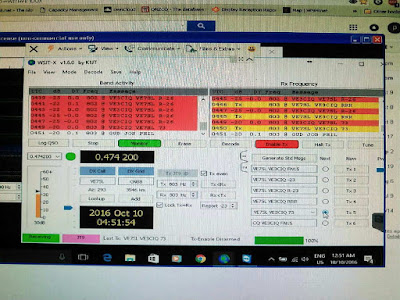 |
| Screen shot of QSO from VE3CIQ's end |
| VE3CIQ - 630m Station |
| VE3CIQ - Homebrew 630m Class-E Transmitter |
| VE3CIQ - 630m Linear-loaded Antenna |
Phil's station stands as yet another fine example of those living in the suburbs without a lot of room for antennas yet still able to successfully operate and explore our new 630m band. With a little ham-radio creativity, it's surprising how well a small station can perform, especially when the propagation co-operates.
Following our contact, I moved back to the WSPR section of the band and continued beaconing overnight.
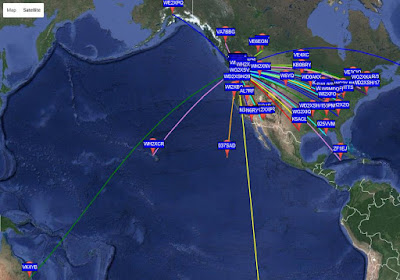
Apparently Phil and I picked a good evening to run a sked as the overnight WSPR map shows it to have been the best night of the new DX season so far, with forty-four individual stations reporting my signal via the WSPRnet website.
 |
| courtesy: http://wsprnet.org/drupal/ |

