Posts Tagged ‘homebrew’
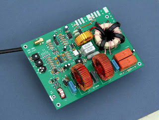
 The GØMRF Class-D 630m Transmitter
 |
| courtesy: www.g0mrf.com/ |
Dave, GØRMF, long time LF proponent and ardent home-brewer has recently posted construction details of his new 630m transmitter.
It is a readily reproducible design that may be of interest to those looking for a transmitter capable of developing full ERP power output.
From Dave's description:
This amplifier is based on the ‘300W Class D Transmitter for 136kHz’ published by the RSGB in Radio Communication and reproduced in the LF Experimenters Handbook by Peter Dodd G3LDO.
This circuit, updated and modified for 630m, uses 2 MOSFETs in push pull driven by square-waves from a CMOS D-type flip flop. The power can be varied from around 25 to 300W by increasing the supply voltage over a 12 to 32V range. Circuits are included to protect against excessive supply current and high reflected RF power.
The amplifier is suitable for any non-linear mode. Examples include CW, QRSS, WSPR, JT-9, JT-65 and FSK.
The circuit has been built on a dedicated double-sided PCB measuring 164 x 120mm. For ease of construction 90% of the components are leaded but it has been necessary to use a few surface mount devices as the normal DIP versions of some ICs are increasingly difficult to find.
In many respects, this circuit is similar to my own homebrew transmitter which can be used on both 630 and 2200m. Although Dave has built his circuit on double-sided PCB, the project would be equally at home on one-sided board or even constructed 'Manhattan' style, the method I chose. This latter style lends itself to easy component swapping to optimize circuit performance.
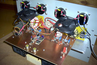 |
| VE7SL 2200m / 630m Manhattan-style Transmitter |
In addition, Dave's website contains several interesting circuits that might be of interest to those getting started on 630m.
 First VK-VE 630m Contact!
 |
| courtesy: https://www.google.ca/maps |
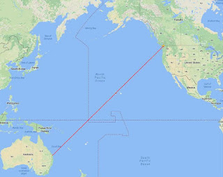
Shortly before sunrise yesterday morning, VK4YB (Roger) and I were able to work each other on 630m ... 475.300 kHz to be exact!
This is the first-ever QSO between North America and Australia on the relatively new 630m MF band. As well, at 11,802km, it presently represents the furthest two-way contact on this band, worldwide ... but I don't expect this record will last very long once the U.S. gets the band as I believe Roger's fine station is very capable of reaching much further afield.
Our contact on JT9, the WSPR QSO mode, was made at 1319Z, about 30 minutes before my local sunrise with the sky surprisingly bright. Blog readers will know that Roger and I have been carefully watching the pre-dawn Trans-Pacific propagation path for the last week. I have been checking-in with him via the ON4KST LF/MF chat page every morning at around 0345 local time at which point a decision is made ... "get out of bed and head for the shack" or "go back to sleep". Each morning's (or in Roger's case, each evening's) propagation quality is assigned a code number by Roger, based upon what he has been hearing during the early evening hours ... a '6' or below is 'sleep-time', a '7' is a 'you decide' while an '8' or above is 'get your butt moving'.
Yesterday, Roger issued a 'code 7' but as I joked with him later, I think he tricked me as it seemed more like a '6.5' from this end! Trans-Pacific conditions were very good about 500 miles to my south but seemed to drop-off quickly much further to the north. I also need to get over a significant obstruction immediately to the SW of me and in line with Roger. That's me directly at the base of the hill on the right while the remaining peaks are on nearby Saltspring Island and then Vancouver Island before reaching the open Pacific.
 |
| courtesy: http://www.heywhatsthat.com/profiler.html |
I believe this requires some enhancement of high-angle arrival (and departure) which often occurs around dawn due to a short period of ionospheric 'tilting'. This is often noted by topband operators near their local sunrise, who regularly observe stronger signals on low (cloud-warming) dipoles than they do on their normal large (low-angle) verticals or beverage antennas.
We enjoyed significantly stronger conditions a week ago, but unlike Thursday when I could run at full 5W EIRP, I was only able to generate a little less than 1W EIRP at the time. So far, this week, conditions have been improving steadily each day, from a 'code 3' to a 'code 7'. Hopefully they will continue to improve and we can do it all over again sometime soon.
With my new antenna / transverter / amplifier relay control box working nicely, it seems that Roger and I can now fully take advantage of TP propagation from 'mediocre' to 'excellent' but we have yet to see just how good it can get.
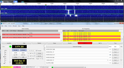 |
| Roger's signal is at +1100Hz |
It is hoped that our contact will inspire new interest among amateurs worldwide and particularly in North America. If you are planning a station, it seems that the main mode of two-way communications will be CW or JT9 ... a simple transverter would allow both modes as well as the use of the WSPR beacon mode. More information may be found here as well as in earlier 630m blogs.
See also: http://www.arrl.org/news/a-record-breaker-on-630-meters
 Transverter-Amp-Antenna Relay Control Box

As mentioned in my last blog, using a transverter to drive a separate amplifier requires some method of switching system in order to automatically handle the antenna, transverter and amplifier input / output ports. To run a relay switching system in the WSPR or JT-9 modes requires that the switching be controlled by the transceiver's PTT line which in turn is controlled by the WSPR software. Using VOX keying is out of the question as it causes the relays to be 'hot-switched' and with higher power will eventually lead to their demise.
For many years I managed PTT line control via my laptop's comm port but these are now things of the past, requiring switching to be done via the USB port. There are many commercial products available that will do this nicely as well as handle the audio feed from radio to computer and vice-versa, but I found that my homebrew version worked just fine. Making it work via the USB port however required a serial-to-usb converter. This was described here, in an earlier blog and for the few dollars invested has proven to be a very reliable interface.
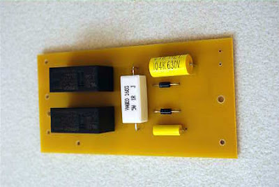
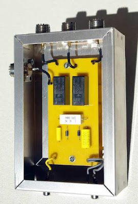
The schematic of the switching control unit is shown below. It uses two inexpensive OMRON G2RL-1-E DC12 relays purchased from Digikey. Although not coaxial, the $3.09 (U.S.) relay will easily handle a kilowatt as decribed by W6PQL. These relays have large contacts, rated at 16A. I added a few extra components that absorb any relay switching transients as well as remove any RF on the control lines.
 |
| Relay Control Unit |
 |
| Keying Line Damper: courtesy: KK5DR |
I must say a few words about Digikey's service. I really am amazed at what a superb job they do in supplying hobbyists with small orders. So many companies nowadays cannot be bothered with such things or demand a large minimum order for the privilege of handling your purchase! From what I can tell, Digikey bends over backwards to help out the little guy, with no minimums as well as dirt-cheap, fast shipping. Living in Canada, I'm used to U.S. dealers making me jump hoops to place an order, only to find out that the cost of shipping is often prohibitively high or they ship only via UPS which I will not accept.
I placed a small two-page order with Digikey via their excellent web site on a Tuesday afternoon. On Friday morning, there was a knock at my door at 0800 hours ... it was a courier service delivering my parts! To put this in context, I live on a small island in the middle of Georgia Strait, accessible only by air or by ferry. To me this service is incredible and the cost of postage was only $6.00 (U.S.). I really have no idea how they do this but they obviously have put into operation a very efficient system ... hats off to them and their skilled management that has figured this all out. A few years ago I sent in orders to both Digikey and to Mouser, each within an hour of each other. Like my recent order, the Digikey parts arrived in just a few days while the Mouser parts took over three weeks ... perhaps things have changed since then but this is the reason I use and recommend Digikey whenever I can.
Once I had the needed parts, I quickly built a PCB for the switcher and put it together in a day so that I might begin 630m skeds with VK4YB as soon as possible.
If you would like a full-size layout suitable for the iron-on toner PCB construction method, I'll be happy to send you one via email.
The first test run with VK4YB at 0300 local time proved problematic. When I fired up at full ERP, I immediately saw some output instability on the scopematch screen. Before I could shutdown however, I had blown a FET in the amplifier, shutting me down and sending me back to bed to worry about the situation.
Having had time to think about the problem made me suspect something in the new relay changeover unit since that was the only new variable in the system. I suspected that perhaps the relays were not fully seated before being hit with full RF output and the possible hot-switching had caused enough short-lived SWR to take out the very reactance-sensitive FET final. In many years of operation with the amplifier, this was the first blown FET I have had. When I built it, I made sure that the FETS would be easily accessible (see below) should such an occasion arise ... unlike my initial transmitter, where replacing a FET was a nightmare.
Fortunately, when FETs go south on a push-pull amplifier, only one FET will blow ... whichever one was conducting at the time, thus preserving the remaining FET. I flipped a coin and unsoldered the source lead of the left hand FET and measured it. Sure enough it had a drain-to-source short. My day was off to a better start. Once replaced, I set out to determine what had caused it to blow in the middle of the night.
Since I didn't want to blow another FET, I could only 'key-up' in very short bursts and see if the instability was still present. I put the amplifier on a dummy load and everything seemed normal but when put onto the antenna, it reappeared. Suspecting an arc in the loading coil, I checked it carefully. I indeed did find a charred blackened section near the top high-voltage end of the coil but that could have been a short-lived event from the past as I'm sure small crawly things often meet their demise between the windings without causing any problems other than a quick puff of smoke or a short-lived arc to the PVC coil form.
After cleaning the coil and removing any carbon paths as well as giving it a few coats of varnish, I was hopeful that the problem would be gone ... but no, the scopematch indicated it was still misbehaving. As well, I could hear a weak but audible high-pitched oscillation coming from somewhere in the amplifier's circuitry. I suspected that it came from one of the output transformers but with the fan noise it was impossible to accurately locate the source of the rogue 'squeal' when briefly keying-up.
Fast forward several hours of pulling out what was left of my hair and I was no further ahead. The amp continued to work fine at high power, via the new relay system, into my dummy load but into the perfectly matched antenna, the problem remained. It was at this point that I decided to look at the input signal from the doubler, a nice squarewave at 950kHz for the amp's divide-by-two input chip. The scope instantly indicated a dual squarewave with more than one frequency present!
 |
| Recently built W1VD 'Frequency Doubler' |
It looked like the doubler was not getting enough 475kHz input to actually double properly and its output was a mixture of 950 and (mostly) 475kHz. The amp's divide-by-two input would then try and turn this into a mixture of 475 and (mostly) 237 kHz which the highly-tuned antenna system would balk at, producing the unwanted FET-killing reactance. Being passive and none-reactive, the dummy load was quite happy to take the signal all day long if I let it.
With the mystery solved, full ERP beaconing and scheduling with VK4YB has begun once again, but the TransPacific path has been stingy for the past few mornings ... hopefully this will change now that I'm ready again, barring any further complications.
 Getting Ready For The ’29 QSO Party

Although the Bruce Kelly 1929 QSO Party is not until December, now is really the time to be putting something together if you've been thinking about getting in on the fun this year!
Like almost all of the operating in 1929, this is a CW only affair and if you've taken a listen in previous years, you know that the chirps, yoops, sudden frequency excursions and musical notes are all part of the original difficulties faced by the boys of '29 as they struggled with the relatively new adventure of 'amateur radio'.
Why 1929 you ask? It was the Radio Act of 1927 that came into effect in 1929 that laid out the foundation and future of amateur radio, with most of the early tenets still in effect today. The BK QSO Party celebrates the turning point in what had been pretty much a radio 'free-for-all' up until that time. Real progress was made quickly once the ground rules were established.
Rules of the BK Party require that all transmitters use tubes that were available in 1929 or earlier and must be self-excited ... no crystals allowed! This might seem to present a daunting task but in reality there are many readily available tubes that will make your transmitter legal.
In three previous blogs I've outlined some of the construction options available to new BK entrants and you can probably find enough information there to get you well on your way to some mid-winter fun. You will find links to these on the sidebar to the right.
Over the past three years I have posted a lot of 1929-related material, covering construction as well as BK Party activity. You can get all of these '29 blogs here and get enough bedtime reading for the week and hopefully, enough inspiration to grab the soldering iron and think about throwing something together for the party ... and it doesn't have to be pretty, as long as it works and is 'legal'! As well, my website has detailed construction information for three of my own '29-style transmitters.
I'm always impressed with the level of operating seen in the BK Party. For some reason, these guys can copy the weakest most awful sounding signals with ease. If you can get something going with a couple of watts or more, I guarantee that you will be heard and will work many of the '29 stations ... just don't wait to late to start building as I'd hate for you to miss all the fun!
 Summer SMT Project
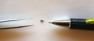
Over the past week, I've been playing with my 630m transverter summer project.
It's not the normal type of transverter that would produce a signal on 630m (~475kHz) but rather, one that will produce a signal on twice this frequency. My630m amplifier, using switching FETs, was designed and built with a 'divide-by-two' input circuit, to allow for greater frequency resolution when first constructed as a 2200m system. I really don't want to modify the transmitter and prefer just to be able to unplug my DDS and plug-in the transverter, allowing me to run WSPR, JT9 and several other digital modes when needed.
So far I've not been able to get the transverter to produce the desired low voltage 950kHz squarewave output, although I'm closer than when I began the troubleshooting.
My circuit is basically a G3XBM 630m transverter, without the FET final amplifier. Instead, the driver feeds a full-wave rectifier frequency doubler for 630m, designed and published a few years ago by Jay, W1VD. Although I can get a squarewave end result, I think harmonics creeping into the process earlier down the mixing chain are causing non-symmetry in the output.
 |
| 3.2MHz signal out of oscillator buffer stage |
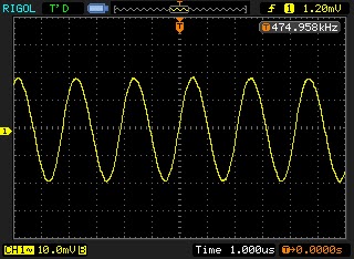 | |||
| 475 kHz signal out of mixer stage |
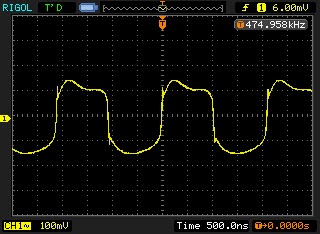 |
| Signal out of 'squarer' stage |
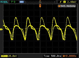 |
| Signal out of full-wave bridge |
 |
| Signal out of LPF |
 |
| Asymmetrical squarewave from 4046 output |
I've tried a 3-section LPF with a cutoff of ~600kHz between the mixer output and the next stage, trying to knock down the 'sum' frequency of 6.875MHz and any crystal harmonics but have since replaced this with a 630m diplexer at the mixer output to pass anything below 1MHz to the squarer and anything above 1.5MHz to ground. I'll keep playing with it ... until it works as it should or I have no hair left to pull out. I may also just rebuild the circuit, Manhattan-style, with normal sized parts, making it much easier to change or modify as I need. The scope grabs shown above are with the diplexer in place at the mixer output. It seems like something in the full-wave frequency doubler is amiss. I've looked at T1, the bifilar transformer several times but don't see anything odd but that's the stage where things seem to go south. Maybe it's an impedance matching-thing, something I'm yet uncomfortable with when it comes to properly matching various stages.
I also now realize that the section of transverter I have chosen will require post-mixer filtering, not shown in the schematic. Not using the last stage (FET PA) and its associated filtering, has no doubt caused more harmonics to appear in the output than anticipated. If I redesign and rebuild, I will add an LPF after the crystal oscillator as well as at the RF input port and pay more attention to post-mixer filtering.
Another route to try, rather than the W1VD doubler, may be this 4069 IC doubler or a similar 4011 doubler.
Although the project outcomes have not yet been achieved, the process has been a positive one in a couple of respects and well worth the time spent so far.
I have learned that working with the 1206-sized SMT parts is much easier than suspected and in fact, populating the board with these tiny parts was a lot of fun. The 1206-sized parts are at the 'large' end of the SMT size-spectrum ... rest assured I won't be going any smaller, at least for now.
The other positive outcome was knowing that my PCB design process can work well with the narrower lines, pads and much smaller IC footprints. I still design my boards using MS Paint and have always been happy with the ease at which it works. I know many might scoff at MS Paint but it really is a very versatile little program, with a short learning curve, unlike many of the more sophisticated PCB design programs.
And one more positive outcome. I used the project as an excuse to purchase a new soldering station ... one that I had been lusting over for a few years as it is very SMT-friendly compared to my old Weller clunker. It also has an electrically isolated tip, unlike my Weller. The Hakko FX-888D turned out to be everything I had hoped and was no doubt part of the reason that I found the SMT process so enjoyable.
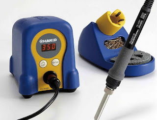 |
| Add caption |
 Field Day – ’29 Style!
 |
| courtesy: WA3TTS & NO3M |
In Eric's own words:
I had a 1920/1930s style Field Day setup this weekend and a bunch of guys over. 80M doublet with homebrew open wire line (approx 550 ohm), the transmitter was a 27-24-24-865 job more or less straight out of July 1931 QST, but with a Hartley instead of crystal oscillator. 27 tuned to 80M, first 24 to 40M, second 24 also 40M, and the 865 on 40M. About 10W. Never did get a chance to try her out on 20M by using the second 24 as a doubler.
I also built the complementary amplifier using a 203A from the August 1931 QST article. I had not even tested the amplifier, only having been finished at 1AM Saturday morning!! It is somewhat different in that the grid circuit is composed of the driving rig's antenna coupling coil/cap, re-wired to be in parallel, not series, of course. It was coined as being a good amp for any existing power oscillator or MOPA, We did a quick job of neutralizing while the gang was here and fired it up..... no modern measurement devices in sight, so we were only going on RF current. 0.9 amps into 50 ohm (pre-tuned the homebrew link coupled, balanced tuner with an analyzer beforehand)... so about 40 watts. I was hoping for 100W.... anyways, after most guys left, a couple of us starting messing around with it more, mainly tightening the output coupling of the MOPA and amp tanks. NICE! 1.45 amps, ie. 105W on 40M.
Anyways, I'll have a full writeup and photos on my website in a few days. We used an HRO5 for a receiver; everyone commented on how good it sounded and well it handled. Of course, this is from a bunch of guys that grew up with this stuff and/or has owned one at one time or another. Everyone had a great time and lots of good discussion and visiting, including 153 QSOs with that pile of junk!
73 Eric NO3M
Most will agree that Eric's station is far from a "pile of junk" as his superb homebrewing skills are clearly evident! Setting up this old style gear can be challenging at any time, but doing it for an outside weekend operation must have been a ton of work. Well done Eric!
For more information about building and operating '29-style transmitters, see the links on my blog sidebar.
 DIY Powerpole voltage and current meters
Powerpole voltage and current monitoring is quite nice to have. One can buy commercial meters, but due to the availability of nice and cheap modules, it is very easy to make them oneself.
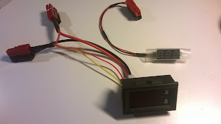
To the right you’ll see my combined voltage and current meter as well as my volt-meter on top of the power supply.
Both of the modules have been bought on Ebay:
- Miniature 0-30 V DC LED 2 wire Digital voltmeter (371333527599) where the display is 22 by 10 mm. Cost slightly more than $1
- 0-100 V, 0-10 A Dual Voltmeter Ammeter (262455987311) costing less than $3. The module size is 48 x 29 x 26 mm and the letters are 7 mm tall just like the miniature voltage display.
- Related post: “New gadget measures negative resistance“

