Posts Tagged ‘homebrew’
 DIY Powerpole voltage and current meters
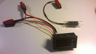
Powerpole voltage and current monitoring is quite nice to have. One can buy commercial meters, but due to the availability of nice and cheap modules, it is very easy to make them oneself.
To the right you’ll see my combined voltage and current meter as well as my volt-meter on top of the power supply.
Both of the modules have been bought on Ebay:
- Miniature 0-30 V DC LED 2 wire Digital voltmeter (371333527599) where the display is 22 by 10 mm. Cost slightly more than $1
- 0-100 V, 0-10 A Dual Voltmeter Ammeter (262455987311) costing less than $3. The module size is 48 x 29 x 26 mm and the letters are 7 mm tall just like the miniature voltage display.
 VE3AB Netty Electronics
 While ordering components for my 630m transverter project, an internet search for some needed FT-37-77 cores brought me to the website run by Earl, VE3AB in NE Ontario.
Purchasing just a small number of parts can usually be expensive, considering the high cost of mailing these days but in this case, the toroids and a few other parts turned into a real bargain. Earl is a retired Defence Department Manager and Technical Specialist and has one of the most colorful and informative sites that I've ever run across. The extensive, somewhat 'eclectic' site, might at first appear to be a bit disorganized but it really all works nicely once you delve a little deeper ... and there are many layers on Earl's site. It really is quite different and one thing that comes through is his passion for doing things the right way!
It seems that Earl's two main passions are fishing and supplying quality components at good prices. His dirt-cheap shipping to both Canada and the U.S. is something not often seen any longer, as shipping costs often make small purchases totally uneconomical. Forgive me if this sounds like a blatant plug for Earl's business ... it is not. It's just that I found his site extremely interesting and very different from most ... the fact that he is offering something that many hams might find helpful, is my main motivation.
The introductory 'ham radio' page contains, among other things, a collection of Earl's articles describing repairs on many solid state transceivers while his 'Netty Electronics' page describes his small home-based component selling and acquisition activities. His 'ham electronics magazine' page contains articles on working with circuit boards (re-capping, repairing, de-soldering), antenna articles as well as numerous articles on components, all authored by VE3AB. Earl's website and free services are all financed by personally using monies obtained through sales of parts and part radios as he sees it is a service to the amateur radio hobby, which he obviously loves deeply.
Earl specializes in solid state devices of all description, from vintage to modern. He offers a vast selection of parts for older radios and has information on repairing dozens of older solid state rigs. All parts are tested or guaranteed to be working within specs.
His pages contain extensive information describing his tests of popular Chinese-made transistors, such as this one describing a batch of dual-gate MOSFET BF981 transistors. His 'test' pages are definitely worthy of your attention and, for many, might be a bit of an eye-opener.
If you are looking for a manual for an older rig, Earl has an extensive offering of free manuals on his site. If it's not there, he can probably get it for you.
He is continually buying up collections of older components, as well as new parts ... if you have stuff to unload you might wish to check with him as so many of these valuable parts end up in the trash as shacks go silent. His extensive list of components can be found here. ... you may just find that special part you've been looking for.
One of Earl's goals for the website is to put up a search-engine for his parts but in the meantime, I found my browser's "Find" function worked well in sorting through the large list.
There is enough interesting information on his pages to keep you reading for hours and I find the random nature of much of it rather attractive. Earl says that changes to the site are coming but I hope they're not too drastic ... I kind of like it just the way it is!
 630m Transverter Project
 I've ordered parts from Digikey for the summer workbench project, a 630m transverter. With the nice 630m WSPR signals received here from Roger (VK4YB) this spring, I think it might be possible for us to work each other using JT9, if the path continues to improve over the next few seasons. On more than one night, Roger's signal was at JT9 QSO levels and had we been on a schedule, a QSO may have happened. Roger's signal was peaking late in his evening, which for me will require making schedules in the wee hours of the morning.
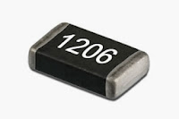
I've been wanting to build another SMD project for some time since making a little SMK-1 40m transceiver several years ago. This was a very inexpensive kit put out by the NorCal QRP Club as a way of introducing SMD construction techniques to beginners. I found working with the 1206 sized parts (basically the largest ones commonly available) to be fairly laborious and would only solder a few parts at a time before setting it aside for the next day. I think my frustration had a lot to do with my positioning and soldering methods and I'm anxious to try doing it with a more refined technique. As I recall, there were 72 SMD components on the board and it took me a couple of weeks to finish it all.
 |
| My SMK-1 40m SMD transceiver |
The parts I have ordered are also 1206 sized but the older I get, the smaller these things seem to look. The transverter will be based partially on the popular G3XBM circuit but will eliminate the PA. Instead, I'll just use a few volts of the transverted squarewave signal and a doubler, so that I can feed the signal directly into my present homebrew amplifier which uses two switching FET modules into a power combiner. Hopefully this system will let me run several of the non-linear digital modes such as WSPR, JT9, JT65 etc.
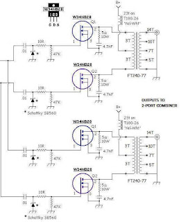 |
| My 630m PA |
As a way of getting back into the SMD-soldering groove, I have ordered and now received, an "SMD Practice Kit" from E-Bay ... a real bargain at $1.78!
 |
| courtesy: Tradeworld2105 |
Although there are many similar practice kits being offered on E-Bay, this was the only one I found that had two IC's to practice with ... all of the others had just one. Since the transverter's doubler circuit has an IC chip, a couple of practice opportunities will be helpful. My only hope is that I don't run out of SMD steam with the practice board before getting down to the actual transverter board.
As soon as the parts arrive from Digikey, I'll start designing the transverter's PCB ... but with all of the usual distractions of summer, as well as trying to maintain vigilance on the magic band once again, my summer project may not progress as quickly as I hope.
All of this assumes that my old eyeballs hold out as well.
 Inverted L
I needed a cheap and relatively unobtrusive solution and I found one in Len Paget's (GM0ONX) design for an inverted L. The full details were printed in the Practical Wireless magazine several years ago and PDFs are available for download from Len's website. The designs make use of coaxial traps, one for the 80m version, two if you want to add a top-band (160m) option.
Opting for the smaller 80m version I set about building one. Using an old fibre-glass fishing pole about 5m high at the far end of the garden tucked behind the summer house which I could collapse down and then retract the wire elements when not in use so hiding it from view.
The fun and interesting part was building the trap. They are formed by coiling some coax, in this case RG58, round a former such as plastic waste pipe. I had a bit of scrap pipe but it was 32mm not the 40mm diameter type described in the article, thinking it couldn't make 'that much difference' I built one using the same number of turns but the resultant antenna wasn't anywhere near resonant according to the analyser.
I decided I needed to test the trap's frequency response. I found a YouTube video by Dave Tadlock (KG0ZZ) where he demonstrates using a MFJ 'Grid Dip Meter' adapter on an MFJ antenna analyser to test coaxial traps.
The adapter consists of nothing more than a coil of wire on a suitable former so I made my own to use with my AW07A analyser. It worked a treat and I discovered my trap was way off frequency. In the mean time I had located a useful PDF document by David Reynolds (G3ZPF) which informed me I actually needed 180cm of RG58 round a 32mm pipe to make a suitable 7MHz trap, so I made another.
I made a small video showing the traps and how I tested them.
The resulting antenna seems to perform well, but it does sag a little due to the weight of the trap and wire and the flimsiness of the pole. But I have made a number of contacts on it and used it during the RSGB 80m CC Datamode contest a few weeks back. It was my first go at this contest but once I got the hang of operating it was great fun.
 VK4YB Lights Up West Coast On 630m
 The past few weeks have seen many of the VK 630m WSPR stations making it into North America's west coast and points east. VK2DDI, VK2XGJ, VK3ELV and VK4YB have been the signals most often seen. Particularly dominant is the signal from Roger, VK4YB, the northern-most station, located in Moorina, Queensland, near the Pacific Ocean.
Roger's signal has been decoded locally by myself as well as VE7BDQ and VA7MM, creating excitement over the more normal nightly spots from the central states.
2016-04-13 11:10 VK4YB 0.475646 -28 QG62ku 5 VA7MM CN89og
2016-04-13 11:20 VK4YB 0.475647 -29 QG62ku 5 VA7MM CN89og
2016-04-13 11:28 VK4YB 0.475647 -28 QG62ku 5 VA7MM CN89og
2016-04-13 11:28 VK4YB 0.475644 -23 QG62ku 5 VE7BDQ CN89la
2016-04-13 11:36 VK4YB 0.475644 -26 QG62ku 5 VE7BDQ CN89la
2016-04-13 11:52 VK4YB 0.475643 -25 QG62ku 5 VE7BDQCN89la
2016-04-13 11:56 VK4YB 0.475643 -28 QG62ku 5 VE7BDQ CN89la
2016-04-07 08:54 VK4YB 0.475643 -25 QG62ku 5 VE7SL CN88iu
2016-04-07 09:36 VK4YB 0.475644 -29 QG62ku 5 VE7SL CN88iu
2016-04-07 10:08 VK4YB 0.475644 -29 QG62ku 5 VE7SL CN88iu
2016-04-07 10:18 VK4YB 0.475644 -29 QG62ku 5 VE7SL CN88iu
2016-04-07 11:04 VK4YB 0.475644 -29 QG62ku 5 VE7SL CN88iu
2016-04-13 11:06 VK4YB 0.475644 -24 QG62ku 5 VE7SL CN88iu
2016-04-13 11:10 VK4YB 0.475644 -23 QG62ku 5 VE7SL CN88iu
2016-04-13 11:20 VK4YB 0.475644 -23 QG62ku 5 VE7SL CN88iu
2016-04-13 11:28 VK4YB 0.475644 -28 QG62ku 5 VE7SL CN88iu
2016-04-13 11:32 VK4YB 0.475644 -25 QG62ku 5 VE7SL CN88iu
2016-04-13 11:52 VK4YB 0.475643 -18 QG62ku 5 VE7SL CN88iu
2016-04-13 11:56 VK4YB 0.475643 -22 QG62ku 5 VE7SL CN88iu
2016-04-13 12:16 VK4YB 0.475643 -27 QG62ku 5 VE7SL CN88iu
2016-04-13 12:28 VK4YB 0.475643 -26 QG62ku 5 VE7SL CN88iu
2016-04-13 12:32 VK4YB 0.475643 -25 QG62ku 5 VE7SL CN88iu
2016-04-13 12:54 VK4YB 0.475644 -24 QG62ku 5 VE7SL CN88iu
2016-04-13 12:58 VK4YB 0.475643 -24 QG62ku 5 VE7SL CN88iu
2016-04-13 13:10 VK4YB 0.475643 -25 QG62ku 5 VE7SL CN88iu
2016-04-13 13:24 VK4YB 0.475643 -27 QG62ku 5 VE7SL CN88iu
2016-04-13 13:28 VK4YB 0.475643 -27 QG62ku 5 VE7SL CN88iu
Roger has sent the following information to me regarding his well-planned system:
My QTH is atop of a stony ridge on 10 acres. The previous owner said there was some soil somewhere, but I haven't found it yet! Ground conductivity is very poor, I think. If you drive in two stakes about six inches apart, an ohmmeter says infinity. That's if you can drive in a stake. Because after the first quarter inch you hit shale rock. Interestingly the shale layers are at about 60 degrees to the horizontal. There are some quartz inclusions. Yes, I have tried crushing the quartz and panning it - no gold!
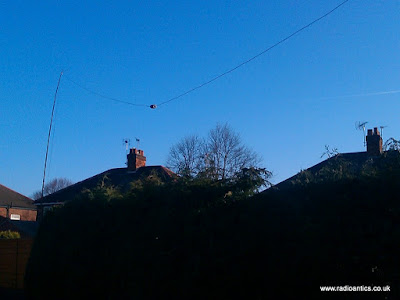
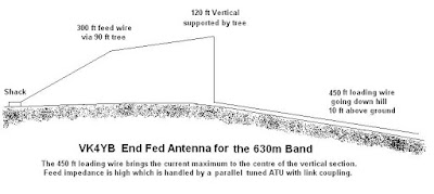
Getting back to my story, I needed to put up a 630m antenna in a hurry. The idea of winding a big loading coil with the rotatable inner coil was a bit daunting. And putting down ground radials or an earth mat was out of the question. So, using only some wire, string and a bow and arrow, this is what I came up with:
I estimate the feed point impedance is about 3000 ohms. The ATU has 48 turns on the secondary, tuned by fixed capacitors of 960 pF in parallel with a 500 pF variable which is about two thirds meshed. The primary is 5 turns fed by the transverter having a 50 ohm nominal output. The impedance at the top of the secondary should be near 5000 ohms, but the antenna feed wire is tapped about two thirds of the way up the secondary coil, which gives 1.03 : 1 SWR. The earthy end of the coil is connected to the mains earth and the metal work of the shed. I haven't tried terminating the far end. I did think about connecting it to the fence wire that runs round the property but I thought that might be a bit dangerous. There would be high voltage points in places. The transverter output is nominally 50 watts, but it is giving about 90 watts in reality.
 |
| Roger - VK4YB |
 Improved GPS reception with a ground plane
My poor-man’s 10 MHz reference based on the Ublox Neo-7M GPS module didn’t always receive GPS satellites reliably enough. Since I rely on reception indoors, conditions were sometimes too marginal to lock the oscillator output to 10 MHz. Inspired by the QRPlabs GPS module of Hans Summers (G0UPL) with its large 6 x 6 cm PCB groundplane, I therefore decided to do something similar.
It definitely helped make indoors reception in my shack much more reliable. The first picture shows the unit with the 8.5 x 6.5 cm single-sided PCB ground plane attached with double-sided tape. The picture below shows it prior to adding the ground plane. I also added a small LED to the right so that I could see from the outside whether the GPS locks properly.
This post is a continuation of these other posts about the 10 MHz reference:
- Just good enough 10 MHz reference (3 Oct 2015)
- Better with SMA (15 Oct 2015)
- Curing amnesia in the 10 MHz GPS reference (19 Nov 2015)
