Posts Tagged ‘homebrew’
 Improved GPS reception with a ground plane
My poor-man’s 10 MHz reference based on the Ublox Neo-7M GPS module didn’t always receive GPS satellites. Since I rely on reception indoors, conditions were sometimes too marginal to lock the oscillator output to 10 MHz. Inspired by the QRPlabs GPS module of Hans Summers (G0UPL) with its large 6 x 6 cm PCB groundplane, I therefore decided to do something similar.
The first picture shows the unit with the 8.5 x 6.5 cm single-sided PCB ground plane attached with double-sided tape. It definitely helped make indoors reception in my shack much more reliable. In addition to the improved conditions for the patch antenna, it probably helps too that the antenna now is shielded from the digital circuitry of the GPS module, the 10 MHz pulse shaper, and the USB interface. I also added a small LED to the right so that I could see from the outside whether the GPS locks properly.
The second picture shows the interior prior to adding the ground plane.
This post is a continuation of these other posts about the 10 MHz reference:
- Just good enough 10 MHz reference (3 Oct 2015)
- Better with SMA (15 Oct 2015)
- Curing amnesia in the 10 MHz GPS reference (19 Nov 2015)
 Single Yagi Moonbounce
 |
| courtesy: JPL/NASA |
In early 2007, I decided to try 2m moonbounce using WSJT's JT65B digital mode. Over the years, moonbounce has gradually drifted away from CW to the much less demanding weak signal digital mode, allowing smaller stations to still explore the excitement of exchanging signals via reflection from the lunar surface. I am fortunate to have an excellent QTH for such an endeavour, being located beside the ocean with a saltwater horizon favoring moonrises, especially during the winter months of more northerly lunar declinations.
 |
| Moonrise from front yard |
I soon realized that the actual numbers appeared very close to predicted values and using an inexpensive 2m FM/SSB 'brick amplifier' (with built-in GasFet preamp) delivering approximately 140 watts, I was able to work 54 different stations over the next twelve months. All of the stations worked were doing the heavy lifting, with the majority running typical 4-yagi H-frame arrays using yagis from 6 to 17 elements each. I did work one station that was using two small yagis during a period of excellent conditions. Somewhat surprisingly, a large majority of the stations I worked were strong enough to be heard audibly from the transceiver's speaker.
I'm always amazed at the truly small amount of RF energy that is actually left, after the round trip to the moon ... yet information can still be exchanged. On 144MHz, the round trip losses are a minimum of 250db. Factoring-in my antenna's gain and ignoring the coaxial losses in 70' of RG213, there is a scant 1.56 x10^-9 W arriving at the moon ... that's .00000000156 W! Considering how much RF is absorbed in the lunar dirt and what's left over for the -125db home trip, it's a miracle that some signals are loud enough to be heard by ear at all. EME is really one of ham radio's most fascinating activities.
Reacquainting myself with the newer version of the JT65B software, and testing out the system, I was ready to go on the next evening's moonrise. Unfortunately the moon was rising just a little too far south to give me a really clear shot and I would be pointing into the next door neighbour's trees. Being unable to track the elevation, my operating time is limited to about two hours per session, over a period of several successive days (or nights).
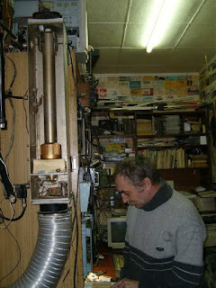
Almost coincidental with the night's moonrise, I heard the strong signals of RX1AS (Alex) in St. Petersburg, calling CQ. I called him and he came right back with my signal report. His station is shown below, along with his large homebuilt strip-line amplifier.
 |
| RX1AS |
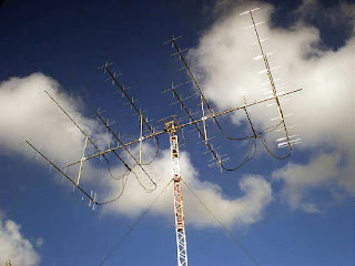
The following evening, the moon was buried even deeper into the trees but initials #56 and #57 were worked ... YL2GD (Gunars), in northern Latvia and RX3A (Nikolay), in Moscow city.
 |
| YL2GD and his EME station |
 |
| RX3A's 2m EME array |
Nikolay was worked with the moon at 11 degrees above the horizon. I'm not sure just what my upper limit for lunar elevation might be with this small antenna but the highest elevation I have worked anyone was at 18 degrees.
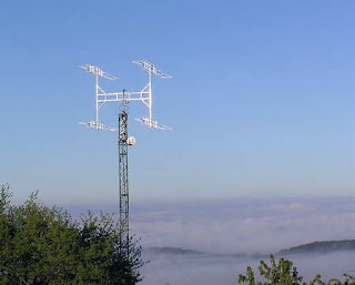
The third night found less activity on the band as well as a more southerly moonrise, burying my target even further into the neighbour's trees. Few signal were heard but one contact was easily completed with I3MEK (Mario), near Venice ... initial #58.
 |
| I3MEK's 4-yagi 2m EME array |
 |
| I3MEK's 2m JT65b signal |
With so many larger (four or more yagis) stations around the world, a huge antenna is not needed to have success on 2m JT65B moonbounce ... nor is an over-the-ocean moonrise. I've also been able to work stations on moonset where I am pointing over hilly terrain and trees, nowhere near the ocean.
The WSJT (JT65B mode) software is freely available and very easy to implement, but spend some time reading the manual and playing with the software first, perhaps getting used to QSO procedures on 20m.
If you are running a small FM/SSB amplifier on 2m, such as the typical 'brick' I have been using, make sure to add a blower to keep the heatsink cool, as JT65 has a 100% duty cycle and these small amplifiers can get hot pretty fast. I use a small squirrel-cage blower from an old microwave oven to direct a blast of air onto the cooling fins.
Wondering where to point your antenna? One handy site that will provide the moon's position in the sky, for any time and any location, is the U.S. Naval Observatory's 'Sun or Moon Altitude/Azimuth Table'. As well, you can keep abreast of real-time activity or set up skeds, via NØUR's Ping Jockey JT65 EME page.
If you do decide to give this a shot, I'd be interested to hear how you do ... maybe your system is big enough already to let us work each other via the moon.
 USB PTT Line Keying

Back in 2007, when I first experimented with single-yagi 2m moonbounce, I constructed an interface that would allow my aging laptop to communicate with my equally aging Icom 821 transceiver.
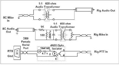
Back then, the shack's old Toshiba laptop (running Win98SE) had a serial (RS-232) communications port and my homebrew interface would let the WSJT software key the PTT line, as well as handle the required 'in' and 'out' audio.
 |
| My Homebrew Radio-Computer Interface |
 |
| Courtesy: KK7UQ |
The 2m Icom has no audio VOX , so to key the radio via the WSJT audio tones, I would need to build a simple VOX system that would key the PTT-line. All things being equal, I didn't really like this idea since it would likely result in 'hot-switching' of the changeover relays and eventually lead to problems.
I investigated the alternative method of hard keying the PTT via the USB port, using a USB-to-serial port adapter, but these were not entirely without problems either. It seems that certain chipsets were worse than others but the FTDI style were less prone to compatibility problems.
I also considered purchasing a Signalink USB interface which would take care of the PTT keying as well as the audio. After researching the Signalink, I found some disturbing reviews that indicated the onboard sound card could create some significant signal-to-noise degradation when used for weak-signal work ... such as EME. The generated noise would likely never be noticed when used on the noisy HF bands, which probably accounts for most Signalink applications, but on weak-signal moonbounce, every db is precious and an elevated noise floor from the sound card would definitely not be helpful.
Further research indicated a really nice line of interfaces being built by Johnny, G3LIV. He offers several models to suit various needs and none seem to include a sound card, which would eliminate the possibility of unwanted noise being introduced ... but before making a decision, I made one final attempt at finding a cheaper solution.
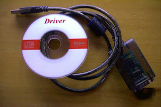
An E-Bay search for an FTDI USB serial port adapter brought up several offerings worldwide, with the majority being in the far east. I found one promising looking low-volume dealer in China, that not only offered the device for $11.99 with free-shipping, but also had a 100% feedback rating and no complaints, ever! What the heck. It was the right chipset, assuming it wasn't counterfeit, the price was right and the dealer looked to be doing his best to offer a good product ... I placed the order and three weeks later the adapter arrived.
The adapter was well packaged and included a small CD containing the necessary USB drivers for several different operating systems, including my newer laptop's Windows 7.
I plugged the adapter into an empty USB2 port and sent the device manager to search the CD for the needed files, which it quickly found and installed. The software created a virtual serial port, assigning the adapter to COM port 3. I then set the WSJT switching tasks to COM3 and connected my homebrew interface to the adapter via its DB9 serial connector. To see if the new adapter would really work, I instructed WSJT's JT65B software to turn on the transmitter before sending a test tone, which hopefully would key the PTT line ... and it did! It seemed that my $11.99 investment was doing the job perfectly. Thankfully, none of the online horror stories that I had encountered regarding USB serial port adapters, had been encountered.
If you need something of this sort, I can recommend this particular product as well as the E-Bay seller. If you are starting from scratch, the entire interface could be easily built, using new parts, including the USB adapter, for just a few dollars and I may, in fact, re-package everything into one compact box, USB adapter and all.
But hold on ... I think I see a big bright moon rising at the moment ... (cont'd)
 PAØRDT E-Probe Improved VLF Noise Performance
 |
| courtesy: http://www.leeszuba.com/projects/ |
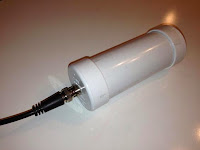
A recent blog posting of four videos showing the installation of a new (Roelof-made) PAØRDT active E-probe antenna revealed that there appeared to be a difference between his earlier model and his latest. It was noticed that the noise ingression levels were different between them, with one showing less noise on LF than on HF, while the other one behaved just the opposite. The newer PFU has the antenna ground isolated from the receiver's ground while the older one does not. Noise coupling, with the new one was higher on HF and lower on LF, which was just the opposite of what was noted with the older unit with its un-isolated ground ... overall LF performance over the newer system was deemed to be better as seen in the final video here.
The only difference seemed to be in the coupling isolation transformer, used in the power feed unit (PFU), likely similar to the one shown at the bottom of this page.
Roleof's transformers are wound on a Magnetics 0W40705TC toroid, whose high mu ferrite has an Al value of ~8350. I mentioned to Roelof that is seemed unusual that the noise levels would be greater on HF than on LF, with the new transformer, as usually it's the other way around when it comes to noise. The changes noted in the video lead to further transformer testing by Roelof, who indicated :
The isolating transformer consists of two bifilar windings on a high mu core. My guess is that the interwinding capacitance spoils the isolation at HF. I have just tested an isolating transformer with two separate windings opposite each other on the tiny core. Sure enough, this solves the feedthrough at HF and VLF performance is not impaired at all.
I have never given this a second thought as I believed it was specific for my location. Never too old to learn!
found the following.
The current transformer with a twisted bifilar winding is a
transmission line transformer. In a 50 ohm system, it covers 4 kHz (!) to 200 MHz at -3dB. Which is very good.
The new one, using the same core and separate windings is an other
story. It covers just 4 kHz to 8 MHz at -3dB. At 30 MHz the loss is
13 dB. So, excellent for VLF / LF/ MF, it won't do for upper HF.
I will try other core material and see if a feasible compromise is
possible.
To be continued.
further...
I first tried a FT-37-43 toroid with 10 turns for each winding.
This core is suitable for higher frequencies and I expected it to
work better than my high mu (8300) cores.
Nope, it was far worse and at 30 MHz the loss was already > 20 dB.
I reverted back to my magical cores and reduced the number of turns
to 3. This yielded a nice bandwidth (-3dB)from 50 kHz to 50 MHz.
Used in the mini-whip interface, there is no more a difference
between shared grounds and isolated grounds on either VLF / LF or
HF.
Though the lower -3dB point is at 50 kHz, I still have excellent
reception of the Russian Alpha stations between 10 and 15 kHz.
It looks like this transformer is an excellent compromise for this
purpose.
I have often found that in practice, high mu cores are excellent for
wideband transmission line transformers. They are good for
traditional rf transformers as well!
and:
I just have tested a binocular core, the BN-73-202, available from
W8DIZ.
With two windings of two turns each of insulated hook up wire (to
keep interwinding capacitance low), gives a transformer from 80 kHz
to over 100 MHz. In practice reception down to 10 kHz is still
excellent.
There is no difference between isolated or common grounds either.
The coupling with this binocular core is a little better than with a
toroid. At LF / MW, I don't find any loss at all.
The FT-50-75 will do fine with two windings of 4 turns each.
I have some FT-50-77 cores at hand and will see how they work out.
I am surprised at the wide bandwidth that can be achieved.
and:
I have been testing a FT-50-77 ferrite toroid for use as wideband
isolation transformer.
Three turns on the Magnetics (aka magical) cores, give an inductance
of 60 uH. Used as a wideband Isolation transformer, the -3dB
bandwidth ranges from 80 kHz to 50 MHz.
For about the same inductance, the FT-50-77 core needs 6 windings.
Used as wideband isolation transformer, the lower - 3dB point is 100
kHz, the upper is 12 MHz. At 30 MHz the loss is already 8.5 dB.
Though not suitable as wideband isolating transformer, it still can
be used for the range 100 kHz - 3 MHz.
It looks that for good wideband performance the Al value must be >
5000 and the number of turns should be =< 3.
Interesting stuff and the best thing is that it has really lowered
my noise floor!
A summary posting to the RSGB's LF reflector indicates that the new transformer scheme is providing quieter VLF reception and good performance up to 200MHz
For years, I have been using a rf - isolating transformer to
separate antenna and receiver ground.
This is a home made transmission line transformer, consisting of 11
bifilar turns on a small high mu toroid (AL=8300). The inductance is
1.2 mH. The measured -3dB bandwidth in a 50 ohm system covers 4 kHz
- 200 MHz.
It appeared that the isolation was not perfect, due to the
inter-winding capacitance. I have made a new transformer on the same
core with two windings of each tree turns. The windings are opposite
each other on the core. The bandwidth is now 45 kHz - 50 MHz. The
loss is 1.3 dB.
Despite the raise in the lower -3dB point, reception at VLF is much
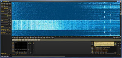
improved due to lower noise ingress. See attachment.
The screen runs from 1 kHz - 13 kHz. At the right hand the dashes
from the Russian Alpha system can be seen. The white band is with
common ground. Harmonics of the 50 Hz mains can be easily spotted.
In reality the picture will be better,as the sensitivity of the
PERSEUS drops considerable below 10 kHz.
The level of interference on 380 kHz caused by a plasma TV in the
neighbourhood is also much reduced.
An excellent video demonstrating the dramatic effects of isolating the ground in the e-probe antenna system on LF was posted today by PY3CRX. Marcus used the Magnetics hi-mu core with 5 + 5 turns (~ 390 + 390 uh).
For those not having access to the Magnetics material, it looks like the BN-73-202 binocular core is a good performer, from 10kHz - 100MHz. The FT-75 and 77 material also fair well but with differing bandwidths. Cores are available from Amidon as well as from W8DIZ's Kits & Parts.
 Making Weak Signal QSO’s On 630m

As much as I love CW and try and promote its use on 630m, one cannot deny the growing interest and use of the WSPR mode on our newest ham band.
Its ability to dig deep into the noise and successfully decode signals as weak as -30db makes it an attractive method of watching the night-to-night and hour-to-hour propagation magic.
One only needs to check the number of stations logged into the WSPRnet Activity-page, uploading 630m spots each night ... a typical evening will see 60-80 calls listed.
The main problem with WSPR is that it's a one-way, beacon-only mode and it's not possible to utilize it for a valid two-way contact. It's nice to know that station 'A' is able to hear station 'B', and vice-versa, but the only way for both stations to know this is for them to both be monitoring the internet uploads ... if both stations were able to confirm their respective receptions all via radio, then a two-way contact could be claimed. Thankfully, there is another mode that solves this dilemma, without internet intervention and that's JT9.
JT9, developed by K1JT, is a spin off from his JT65 weak signal QSO-mode software developed for EME. JT9 has been tailored for the noisier HF and MF bands and is apparently, about 2db more sensitive than JT65. In the past, I have made several single-yagi EME contacts on 2m using JT65, with many of these QSO's being in the -27 to -29 db range. This would suggest that 630m JT9 contacts could be made at signal levels as weak as -30db!
A recent "630m Activity Weekend" in Europe turned out be a "630m JT9 QSO Party" with dozens of Europeans working each other throughout the event using this weak signal mode with great success. It looks very much as if JT9 may now be the go-to mode for two-way work on 630m when, as is often the case, signals can be easily seen on a visual waterfall display, but are too weak to be heard on CW.
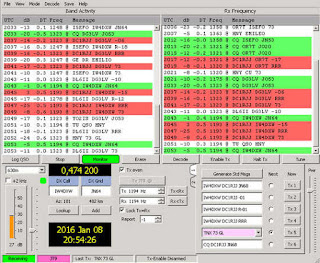 |
| DC1RJJ's 630m JT9 action courtesy: KB5NJD |
On this side of the Atlantic, recent JT9 contacts have been made between several of the U.S. experimental stations. WH2XCR in Hawaii (K9FD/KH6) and WG2XIQ in Texas (KB5NJD) worked on Dec 9th, while WH2XGP (W7IUV), WG2XSV (W0YSE/7) and others have been exploiting the power of JT9 to work around the country.
Such has been the case for me recently, with the arrival of VE3OT on 630m. Since beginning his nightly slow speed CW, QRSS6 beaconing, his signals have been easily visible here every night but only strong enough to hear aurally, on two occasions. It is likely that we could work each other fairly routinely on JT9 but will need to wait for very good conditions to work on CW.
The good thing about modes such as WSPR and JT9 is that they can be used without the need for linear amplifiers in the PA ... class D or E amplifiers, fairly universal in the LF/MF world, can be employed. The most popular route at present seems to be via a homebrew transverter that will allow the use of the station's main HF transceiver (using the tone-generating JT9 / WSPR software) to generate the required 630m RF.
I've been looking for a new radio workbench project to catch my interest and building a 630m transmitting converter is beginning to look more attractive, now that we have another DX target in VE3 land ... of course, if and when the U.S.A. gets the band, there will be an entire new crew of stations spread across the continent to keep the transverter busy!
 GW3UEP 630m Transmitter Tweaks
 |
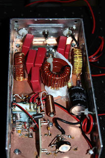
| DF8UO's GW3UEP 630m Tx |
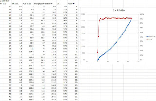
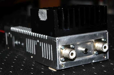
From Daniel's test data, it looks as though the IRF540's are quite happy as long as you keep the transmitter at 100W or less ... anything higher would certainly benefit from the switch to IRF630's as the high efficiency is maintained at least to the 300W level. Something at this level would no doubt benefit from higher-voltage capacitors and heavier inductors as well as a little more heatsinking, enough to shed at least 25 watts of heat between the two FETs.
Daniel drives his amplifier with an Ultimate3, followed by a 10db attenuator, a squarer and into the totem pole driver stage. His own version uses toroidal inductors rather than the original air wound coils.
A pair of GW3UEP amplifiers using IRF630's at ~40V into a small power combiner, should provide ~550W of useful output at >90% efficiency ... more than enough power to do some serious work on 630m.
 Great Circle Map Generator
The map generator is the brainchild of Tom, NS6T, and can be found on his 'HAM STUFF' website along with some other interesting bits. The actual map generator can be found here.The user interface is simple and map generation times are fast. Anyone with a beam will likely be interested in this, should they not already have a great circle map for their present QTH.
I used my six-letter grid square identifier for centering the map. Depending on the 'distance' value used, one can tailor the map for local / regional work or for a worldwide setting.
This is the map generated for a distance unit of 500km and would be helpful for local VHF'ing:
This map was produced when a distance unit of 4500km was used ... nice for the 6m grid square hunter:
This worldwide map was produced with an input of 18000km:
Hopefully you might find the map generator of some value in your own shack.
