Posts Tagged ‘LF’
 Special 630m Activity Night This Fall
"Special Event Planned this Fall on 630 Meters
Experimental operators on 600/630 meters will conduct a special event operation October 31-November 2. The Maritime Radio Historical Society (MRHS), which maintains the KPH/KSM commercial coast stations, will take part in the event.
“This event marks the 106th anniversary of the Berlin Treaty that created the international distress frequency at 500 kHz,” said ARRL 600 Meter Experimental Group Coordinator Fritz Raab, W1FR. “This will be a CW event.”
Raab said some stations will operate beacons on the experimental band, transmitting anniversary messages, while others will simulate the sort of maritime communication that once occurred in this part of the medium-wave spectrum. They will call CQ on a designated calling frequency and then change frequency to complete the contact. Silent periods will be observed.
The activity will occur between 465 and 480 kHz and between 495 and 510 kHz. “Different licensees have different frequency authorizations,” Raab noted. “The designated calling frequencies are 475 kHz for the lower band, and 500 kHz for the upper band.”
Raab noted that this may be the last such event that includes operations on 500 kHz itself. “This band is not being included on new experimental licenses, as it is supposedly reserved for a new maritime-data service,” he explained. He said he anticipates that more information will be released as the event draws closer. "
Not seeing any mention for Canadian activities in the event, I contacted the organizer and ARRL 600m Experimental Group Coordinator, Fritz Raab (W1FR). I asked Fritz if it would be possible for the three active Canadian 630m stations (VE7BDQ, VO1NA and myself) to 'officially' become part of the planned activities. I suggested to Fritz that the three of us could offer the chance for amateurs in both Canada and the U.S. to actively communicate with some of the 630m Canadian stations by working in the 'crossband' mode. Each of the three stations would have their own assigned transmit frequency and, following CQ's, would listen on specified HF frequencies for any answering stations. Fritz was delighted to add us to the program and the next '630 m Activity Night' announcement will include all of the details including exact frequencies.
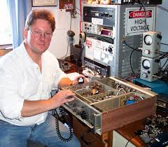 | |||
| Joe - VO1NA |
VO1NA will be transmitting from Torbay, Newfoundland and should be very well heard throughout eastern North America. Joe will be listening for replies on both 80 and 40m CW.
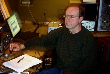 |
| John - VE7BDQ working 2200m - 160m crossband at VA7LF |
VE7BDQ will be transmitting from Delta, B.C., south of Vancouver. John will be listening for callers on 80m CW only. Being a retired Canadian Coast Guard RO, John has many years of experience manning the 500kHz watch when 600m maritime activity was in its prime.
VE7SL will be transmitting from Mayne Island B.C., midway between Vancouver and Victoria, on Vancouver Island. Like Joe, I plan to listen for callers on both 80 and 40m CW.
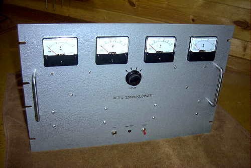 |
| VE7SL - 2200m / 630m TX |
All three Canadian stations are able to muster the maximum allowed eirp for 630m and with the improved propagation of late October, the opportunity for some interesting crossband contacts should be realized on both ends of the continent.
There will be more details well before the event but hopefully you can become part of the fun by giving some of the crossbanders a call on their HF 'QSX' frequencies....and if you know of anyone that might like to participate, please let them know about the upcoming event as, like so many on-the-air activities, the more the merrier!
Your LF Station’s Best Friend – The Scopematch PT.II
 As mentioned in Part I, my construction of the MØBMU-designed Scopematch has proven to be the most valuable piece
of test gear in my LF station. If you plan to become active on our new 630m
band, it is well worth taking a few hours to build as it will make antenna
tuning much, much easier than trying to get your antenna tweaked using other
methods.
As mentioned in Part I, my construction of the MØBMU-designed Scopematch has proven to be the most valuable piece
of test gear in my LF station. If you plan to become active on our new 630m
band, it is well worth taking a few hours to build as it will make antenna
tuning much, much easier than trying to get your antenna tweaked using other
methods.After building and installing the new Scopematch, a quick check of what I thought had been a properly-tuned system, surprisingly revealed that my 2200m antenna was neither matched correctly nor tuned to resonance! In spite of my poor-tuning (using the system shown in my last post), I had still received a number of encouraging reception reports from VE6, Washington and Oregon, giving me false and undeserved confidence in my earlier tuning attempts. The Scopematch soon changed all that.
The complete building instructions and operating description for the Scopematch may be found in "Tuning Aids for the 136kHz and 500kHz Bands" by Jim Moritz, MØBMU.
 |
| Source: Tuning Aids for the 136kHz and 500kHz Bands by Jim Moritz, MØMBU |
As can be seen, a small RF sample taken by the Scopematch is coupled to the inputs of a dual-trace oscilloscope...one channel displaying the antenna current waveform and the other displaying the voltage waveform. When the antenna system has been tuned to resonance and matched to 50 ohms, both sine waves will be equal, in both phase and magnitude as shown below.
Such a condition is ideal and virtually guarantees that your transmitter is looking into a non-reactive 50 ohm load. Many transmitter designs utilized on LF employ inexpensive switching MOSFETs operating in either class-D or class-E modes that cannot tolerate any reactance in their output load. The end result of such a condition quickly produces a growing pile of dead MOSFETs!
 | |||
| Source: Tuning Aids for the 136kHz and 500kHz Bands by Jim Moritz, MØMBU |
If the system is not tuned to resonance, the phase of the waveforms will not be the same and one waveform will lead the other. Whichever waveform is doing the leading indicates whether the antenna is tuned above or below the desired frequency so that proper corrective measures can be taken to achieve resonance.

| Source: Tuning Aids for the 136kHz and 500kHz Bands by Jim Moritz, MØMBU |
The condition shown above illustrates the smaller waveform (V) lagging the larger current waveform (I) which indicates the antenna is capacitive or too high in frequency.With 'I' being greater than 'V', the resistive component of the load measures about 20 ohms.
The condition shown below indicates resonance but with 'V' being greater than 'I', the resistive component of the load measures about 80 ohms.
 |
| Source: Tuning Aids for the 136kHz and 500kHz Bands by Jim Moritz, MØMBU |
The impedance match will be indicated by the amplitude of the two waveforms. Depending on which waveform is higher or lower indicates if the resistive impedance component is higher or lower than 50 ohms. Actual impedance values can be calculated from Ohm's Law using the sampled
waveform values.
It is fascinating to watch the scope patterns during windy conditions when the antenna's large tophat section is being blown around, causing slight changes in impedance and resonance. The two waveforms will expand and contract as well as shift phase slightly...almost as if the system is alive and breathing!
 |
| My 2200m antenna - resonant and matched & a thing of beauty! |
Jim's article goes into much more depth as well as showing alternative methods of construction and is very much worth studying. Over the last few years I have suggested the Scopematch to several LFers who, like me, now wonder how they ever lived without it!
Your LF Station’s Best Friend – The Scopematch PT. I
 If you're planning to get on Canada's newest ham band (630m), or are in the U.S. A. and building for when that day arrives, then you'll probably be interested in today's chatter.
Several years ago, when I first set up my 2200m (136KHz) station under Industry Canada's Amateur Experimental Licensing Program, I utilized a fairly simple method shown in the LF Handbook, of attempting to tune and load my antenna. I had built a small top-loaded wire vertical consisting of a two-wire 50' flattop at the top end of a 30' vertical wire. A large loading coil of about 3 mH at the base of the antenna took care of getting the system close to resonance. As shown below, a variometer was used to fine-tune the system to resonance while the antenna impedance was matched to 50 ohms by tapping up from the base of the loading coil.
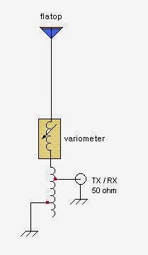
A 2A RF ammeter was used to monitor antenna current, with the plan being to tune and tap for maximum antenna current. It was the first time I had done any LF antenna work like this so it was a true 'learn as you go' project. It sounded fairly simple in theory but actual implementation was more challenging than I thought. What I also should have had was an LF SWR meter in the 50 ohm line as tuning and tapping for maximum antenna current did not guarantee that my system was indeed resonant or impedance matched. As you can imagine, there was much interaction between the two adjustments and I often found myself chasing my tail.
There were some tuning combinations that would peg the RF ammeter, indicating more current than my system was even capable of producing into a 50 ohm load. No doubt my settings were sufficiently 'off track' to create some diabolical impedance / off-resonance combination. I eventually settled on something that looked close but I was never really sure. Several weeks later I built the 'Scopematch' (designed by Jim Moritz -'MØBMU) and have not had a problem tuning and matching ever since.
Of all the devices in my LF toolbox, the most valuable by far is my Scopematch. Basically, it is a coupling device that allows you to monitor the tuning parameters of your LF antenna system. In real time, you are able to see both the impedance condition and the resonance tuning condition by observing the antenna current and voltage waveforms on a dual-trace oscilloscope. It is immediately apparent if your system is impedance matched (or not) and how close to resonance the system is. It will even tell you if your antenna is capacitive and requires more inductance to lower the frequency or if it is inductive and requires less loading inductance to bring it up in frequency.
Besides the dual-trace scope, the Scopematch requires only three parts and is fairly non-frequency critical. I am able to use it on both 2200m and 600m without any changes. More details to follow.
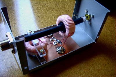 |
| My homebrew Scopematch |
Using The KØLR ‘Antenna Meter’ on 630m
If you plan to become active on Canada's new 630m ham band, one of the first things you're probably thinking about is an antenna and how to make it resonant. Without the proper instruments, determining antenna resonance below the broadcast band can sometimes require a combination of good luck and black magic!
One of the most useful pieces of gear for me has been a simple 'antenna meter' designed by Lyle Koehler, KØLR, who was very active at one time on the 185KHz 'lowfer' band. Although the original circuit was designed to cover a lower frequency range, it can easily be modified to cover the 2200m and 630m bands.
The device is actually a low power (~1/2w) VFO-controlled transmitter designed to look into a 50 ohm antenna system. Since most LF antennas are matched to 50 ohms, either through a separate matching transformer or by tapping up from the bottom of the antenna's loading coil, the 50 ohm feedline from the antenna system is simply connected to the antenna meter's output and the VFO tuned for maximum deflection of the meter. The resonant frequency is then directly read from the calibrated scale of the antenna meter's dial. With most backyard LF antennas having a very narrow bandwidth along with a high-Q, the meter peak is quite sharp and easy to find. Look for a peak meter reading between 50-70ma as you sweep the VFO across the antenna. Normal current values will be very low until resonance is hit.
KØLR's original article gives more details and can be found here.
The 470pf capacitor (C in my diagram) determines the basic frequency range. To modify the circuit for dual range (both 2200m and 630m), I added a SPDT switch at pin 1 of the IC so that I could switch the value of "C". For coverage down to and below 136KHz, I used ~ 725pf (a 680pf + 47pf in parallel) while high end coverage up past 500KHz required just 250pf (220pf + 27pf in parallel). These values should get you very close to the required ranges and once installed it is an easy task to calibrate the tuning scale by listening to the signal on a receiver or measuring it with a frequency counter. I also chose to install the 1M 'modulation' resistor that gives the signal a distinctive FSK note.
The meter will quickly tell you if your antenna is too high in frequency (capacitive) or if it is too low (inductive) so that the proper corrective measures may be taken to resonate it within the 630m band. Once resonant, attention can then be paid to bringing the impedance match as close as possible to 50 ohms and a 1:1 match. Depending on your method of impedance matching, there may be some interaction between tuning for resonance and impedance matching but a perfectly resonant 50 ohm system can be achieved with a little juggling.
Although not updated for several years, KØLR's website contains much good information regarding simple backyard LF antenna systems (both transmitting and receiving), preamps and weak signal receiving techniques. It is well worth a close look if you are designing a new 630m station.
One of the most useful pieces of gear for me has been a simple 'antenna meter' designed by Lyle Koehler, KØLR, who was very active at one time on the 185KHz 'lowfer' band. Although the original circuit was designed to cover a lower frequency range, it can easily be modified to cover the 2200m and 630m bands.
 |
| The KØLR LF Transmitter |
The device is actually a low power (~1/2w) VFO-controlled transmitter designed to look into a 50 ohm antenna system. Since most LF antennas are matched to 50 ohms, either through a separate matching transformer or by tapping up from the bottom of the antenna's loading coil, the 50 ohm feedline from the antenna system is simply connected to the antenna meter's output and the VFO tuned for maximum deflection of the meter. The resonant frequency is then directly read from the calibrated scale of the antenna meter's dial. With most backyard LF antennas having a very narrow bandwidth along with a high-Q, the meter peak is quite sharp and easy to find. Look for a peak meter reading between 50-70ma as you sweep the VFO across the antenna. Normal current values will be very low until resonance is hit.
KØLR's original article gives more details and can be found here.
The 470pf capacitor (C in my diagram) determines the basic frequency range. To modify the circuit for dual range (both 2200m and 630m), I added a SPDT switch at pin 1 of the IC so that I could switch the value of "C". For coverage down to and below 136KHz, I used ~ 725pf (a 680pf + 47pf in parallel) while high end coverage up past 500KHz required just 250pf (220pf + 27pf in parallel). These values should get you very close to the required ranges and once installed it is an easy task to calibrate the tuning scale by listening to the signal on a receiver or measuring it with a frequency counter. I also chose to install the 1M 'modulation' resistor that gives the signal a distinctive FSK note.
The meter will quickly tell you if your antenna is too high in frequency (capacitive) or if it is too low (inductive) so that the proper corrective measures may be taken to resonate it within the 630m band. Once resonant, attention can then be paid to bringing the impedance match as close as possible to 50 ohms and a 1:1 match. Depending on your method of impedance matching, there may be some interaction between tuning for resonance and impedance matching but a perfectly resonant 50 ohm system can be achieved with a little juggling.
Although not updated for several years, KØLR's website contains much good information regarding simple backyard LF antenna systems (both transmitting and receiving), preamps and weak signal receiving techniques. It is well worth a close look if you are designing a new 630m station.
NDB DXing & The CLE183 Results
 |
| WC - 332KHz White Rock, B.C. |
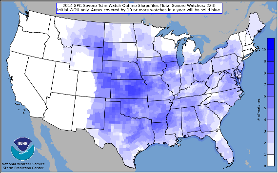 |
| source:http://www.spc.noaa.gov |
One of the beacons in my log this weekend is pictured above - 'WC' in White Rock, B.C. The beacon is located in a residential neighborhood, with homes on both sides...not a typical NDB location.
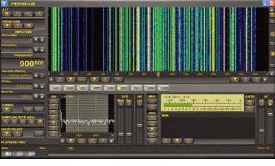
Here is my short log, all captured using Perseus:
06 21 0600 323 W4 Jenpeg, MB
06 21 0600 325 YJQ Bella Bella, BC
06 21 0500 326 DC Princeton, BC
06 21 0600 326 XJ Fort St. John, BC
06 21 0500 328 5J Coronation, AB
06 21 0600 328 LAC Fort Lewis, WA
06 21 0701 328 YTL Big Trout Lake, ON
06 22 0846 329 PJ Whitehorse, YT
06 21 0600 329 TAD Trinidad, CO
06 21 0600 329 X2 Athabasca, AB
06 21 0600 329 YEK Arviat, NU
06 21 0500 329 YHN Hornepayne, ON
06 21 0600 330 3G Peggo, BC
06 21 0600 332 LBH Portland, OR
06 23 1130 332 POA Pahoa, HI
06 21 0600 332 VT Buffalo Narrows, SK
06 21 0500 332 WC White Rock, BC
06 21 0500 332 XH Medicine Hat, AB
06 21 0700 332 XT Terrace, BC
06 21 0600 333 STI Mountain Home, ID
06 21 0600 334 P2 Wetaskiwin, AB
06 21 0700 334 YER Fort Severn, ON
Some might wonder why listening for NDB's would be of any interest. For me, there are a number of reasons:
- the challenge of hearing distant low-powered transmitters below the broadcast band, particularly from one region...for me it is Alaskan NDBs
- the necessity to develop an efficient receiving antenna has led to numerous antenna trials using loops and wires in various configurations
- learning about LF propagation and how it compares with HF
- the ability to compare what is being heard at my location with what is heard just a few hundred miles away can often be surprising (and humbling)
If you are planning a 630m station, listening for NDB's is a good way to test your system's receive capability as there are hundreds of signals to be heard, many of them very close to our new 472KHz band.
An informative Introduction To Beacon DXing by Alan Gale may be found here. To find the location of any NDB's that have been heard in North America, check the always accurate RNA database by Martin Francis.


