Posts Tagged ‘low band receivers’
 Don’t play Ingress at Radio Observatories
A few weeks ago, the IPG got some curious email from some ABQ-ians asking if they could play Ingress at the VLA to capture some GPS-based portals. If you’ve never heard of Ingress, think of it as geocaching with a Virtual Reality spin. Check out their website here.
Ingress is played on smart devices, which require data connections to operate. These data connections are fine and dandy unless you’re at the world’s greatest radio observatory; here they aren’t so dandy.
RF-EMS
Below is a screencap of our RF-EMS (Radio Frequency-Environmental Monitoring System) which captured two WiFi access points (the darker blotches) from an RV containing a Verizon 4G hotspot and another router for something else.
| Your VLA on WIFI |
In the last blog I described the 10′ dish for pinpointing RFI. We also have a (usually) 24/7 monitor that uses some pretty nifty antennas and preamps on a 50′ tower, sending it to an HP 70000 Spectrum Analyzer in a RF-shielded room from which we can record and upload plots like the one above, every day for the past 5+ years.
| RF-EMS Tower and Bunker |
The biggest downfall is adequate locating of interfering transmitters. Currently, I’m designing a method which will allow the IPG to quickly and accurately pinpoint people with any kind of transmitter, be it a cell phone, hotspot, or vehicle keyfob (if we wanted to locate such things). My idea is based on multilateriation, which uses multiple receivers around the site which compare arrival times to calculate a four dimensional location. Keeping the bill of materials as low as possible, simplicity, ease-of-use and network integration (without causing RFI itself) a prime focus.
It may be overkill, but it gives me something to do in the free time.
Other Doin’s: Testing out and Debugging the 74 MHz System
When I’m not having free time, this is what I’m doing. A new feature of the Expanded-VLA is observations on the 4 meter band. The current system in place uses these simple crossed dipoles hoisted a few meters below the sub-reflector.
The cross dipoles connect to our receiver, which hooks up to the rack that magically digitizes the signal and turns it into pulses of light which the correlator feeds upon.
One of the problems we face are things broken that don’t have to do with our antennas and receivers. For example, the first test we do to examine the receivers performance is a band pass plot. Often times, we see something like this:
 |
| A bad bandpass plot caused by a faulty relay in the T301. |
This is ugly! What we want to see is this:
 |
| A beautiful bandpass! You can see 4 band on the left, and P-band in the middle with RFI spikes all over. |
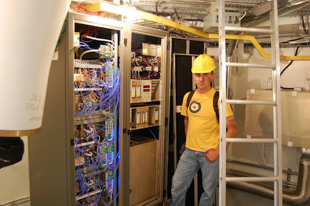
First we go digging in the LO-IF and FE racks for a place to stick a spectrum analyzer to…
| Eric the BAMF next to the LOIF and FE rack. Our culprit is on the left, in the middle of the top rack of modules |
And from that we figure its’ this T301 which does the first IF up-conversion from 0-1GHz to 1-2GHz.
We get a new one, stick it in, turn it on and voila, it’s alive!


