Posts Tagged ‘MF’
 630m Loading Coil & Variometer Update
I've managed to complete my new 630m loading coil / variometer combination but will need to wait for the completion of my impedance matching transformer before I can test it out on the antenna. From earlier tests on 475kHz, it seems that my inverted 'L' needs about 190uH for resonance on 630m so just a small loading coil was needed. The built in variometer will allow the system to be tuned to resonance easily, without the need for playing with taps. Once I had started to wind the main coil, I decided to put on a few more turns than I had originally planned, reasoning that it would be easier to remove turns if less inductance was needed than it would be to add more turns if I fell short.
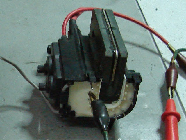
To avoid core saturation at 1kW, my 2200m transformer was wound on two pieces of 'street ferrite', a phrase coined by VE7TIL to describe the abundance of these free flyback cores often to be found in discarded TV's and computer monitors. The ferrite usually has a very high permeability and works well in this application as well as for switching FET amplifier output transformers...and, the price is right!
The challenge is removing the core from its encapsulated shroud without damaging the core. Once you get the hang of it, it is fairly easy to do, but you must work carefully with the brittle ferrite. With the proliferation of LED TV's and monitors, this source of free cores will not be around much longer so grab them while you can ....this ferrite is just too good to throw away!
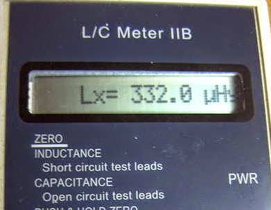
Originally planning for something in the 130-230uH range, the final result produced 177-332uH...certainly more than enough and perhaps a little too much more. I may end up removing a few turns from the main coil as apparently the best variometer efficiency is realised when operated towards the maximum end of inductance, rather than at the low end or when the inner coil is bucking the main coil.
My matching transformer will be similar to the one used on my 2200m system for the past several years. Construction details may be found on the GW4ALG web site. This method of matching, rather than tapping up from the grounded end of the loading coil to find the correct impedance match, is much easier to use and readily allows for changes to be made as the seasons change from winter (wet) to summer (dry).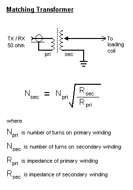 |
| Source: http://www.alg.myzen.co.uk/radio/136/ant_xformer.htm |
 | ||
| Source: http://www.alg.myzen.co.uk/radio/136/ant_xformer.htm |
 |
| Source: http://leoricksimon.blogspot.ca/2007/05/flyback-driver.html |
 A New 630m Loading Coil & Variometer
I've decided, for the time being, to keep my 2200m (136kHz) antenna tuning system separate from the 630m system. This means that I'll need to build a new loading coil, variometer and impedance matching transformer. I'm not really sure why I should maintain the 2200m capability since there is not really much activity here. The only two excuses that I have at present are the fact that it took a heck of a lot of work to get to this point (but it was mostly "fun work") and that the U.S. may be getting the band soon. I'm also not convinced that even if the U.S. does get the band that it would translate into much new activity....so, for the time being, I will keep the system intact.
I've used an online coil calculator to design the coils needed for loading and for the variometer....it will be interesting to see how close the finished values compare with the calculated values. I hope they're not too far off! Here is what the plan calls for:
The main loading coil will be built on a low-loss 6" styrene pipe coupler using #16 solid copper transformer wire, spaced at 3mm. The coil will be elevated above the main form by strips of styrene rod that I have filed small notches into, every 3mm. The rod height will be staggered around the form, gradually stepping down one full turn every 360 degrees. Inside the main coil, the smaller variometer coil will be wound with poly-covered #18 stranded wire on a short length 3 1/2" PVC pipe.
Hopefully I'll get something that tunes from 130-230uH, approximately....if so, I'll not only be happy, but really surprised!
 Smoke Testing The GW3UEP 630m Transmitter
 |
| Drain (top) vs Gate (lower) on testbed Class-E GW3UEP TX |
I've just completed the Muppet-styled printed circuit version of my previously breadboarded GW3UEP 630m transmitter. The earlier version was built "ugly style" in order to optimize part values and measure circuit parameters.
 |
| Testbed (Ugly-Style) |
 |
| Final Version (Muppet-Style) |
Running the TX at 12.8VDC on the drain(s) at 2.3A produces an input power of 29W. The measured power out, after the LPF, is 23W into a 50 ohm load. This represents an efficiency of 80%. When run in the normal speed CW mode, the FETs run cool enough that they would probably not even need a heatsink but if run in any of the QRSS (long keydown periods) modes, would certainly benefit from heatsinking.
Running the TX at a higher voltage of 22.6VDC (on the amplifier only) yields a current of 4A for an input of 90W. Measured output power is 71W for an efficiency of 79%.
Heatsinking would be required at this power level, even for normal speed CW but the finals seem to run just slightly warm. A larger heatsink or possibly a small fan as well would be required for any QRSS CW modes.
I suspect that the efficiency could be further improved yet with very fine tweaking of the output circuit L/C network but the extra few watts gained would not be significant.
At either power level, this easy-to-build transmitter would make a great "first 630m transmitter" for anyone wanting to get started on our new band.
 Wellbrook Loop Plans
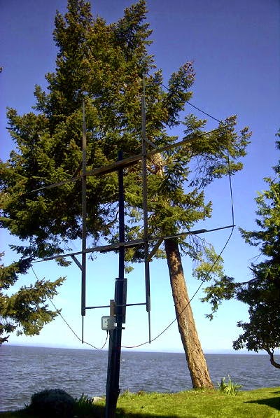 |
| My present 9.5' active loop |
During last winter's DX season I built and played with a number of different preamps for use with my (almost) 10' diameter shielded loop. I had been hoping to get the Burhans Preamp to play-nice above 500KHz so that I might use it for DXing the broadcast band with my new Perseus SDR radio. By bypassing the preamp's LPF, the level of BCB signal delivered by the 10' loop was just too much for the preamp's JFET front end to handle with the consequence being various strong intermod products showing up at several places inside the band. Several different toroidal input transformers produced varied results but none were satisfactory. Although I didn't try it, a smaller aperture loop might do just fine with the LPF removed and even better if there were no blowtorch BCB signals in the vicinity. My particular location, on the east coast of Mayne Island, looks directly across Georgia Strait to several 50KW BCB transmitter sites near the points of nearest landfall. Luckily, this direction is usually in the loop's null when pointing in my favorite target direction of SE/NW for the central U.S. Even so, it would be nice to not have to worry about loop orientation in order to guarantee intermod-free performance.
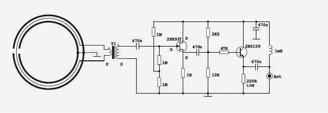
I did have much better success on the BCB using a version of the PA0RDT active antenna preamp, modified with transformer input to match the shielded loop's low impedance to the JFET amplifier input.
 |
| Courtesy: Aldo Moroni |
Gain of the system was adjusted by swamping the transformer's output with various levels of 'R' until there were no signs of intermod products with the loop pointing away from the Vancouver blowtorch signals. The end result was a preamp that had good performance throughout the BCB, even with the big loop, as this recording of French language station, CJBC (860KHz) in Toronto(identifying as 'Radio Canada') demonstrates.
....but unless the loop was oriented in my favored SE/NW direction for most North American targets of interest, there were still a few frequencies that produced some very low-level intermod products. Again, had the loop been just slightly smaller, I think this preamp would do a great job as a wideband loop amplifier for the BCB and above. Although still usable down at 540KHz, performance dropped off rapidly as I went lower in frequency and was not considered usable for the LF NDB band. Perhaps more inductance in the input transformer as well as higher value coupling capacitors would improve LF performance. There is still room for further development of this circuit for LF use with a medium-sized shielded loop.
I recently ordered and received a Wellbrook ALA-100LN loop preamp, which I am anxious to install for the upcoming DX season. With its front-end of 8 JFETS in push-pull parallel, the Wellbrook boasts extremely good strong-signal handling capability within the BCB and below.
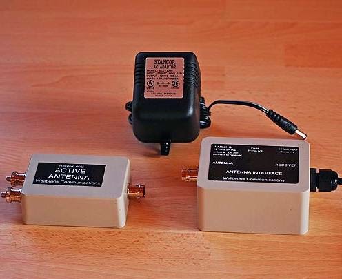 |
| Please visit: http://www.wellbrook.uk.com/ |
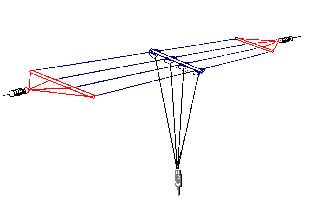
My present plans call for a new and lighter loop frame, this time using PVC tubing in some sort of H-frame. I will aim to make the loop as large as possible while keeping within the Wellbrook's circumference limit of about 21m. Mid-summer doodling has produced one possible front-runner but no final decisions have been made.
 |
| 10' x 20' LF / BCB Loop |
I always savour the design and 'what-if' phase of any new project and the new loop is no exception. Any other ideas for possible frame configurations would be most appreciated.
 VE7 630m CW Beacons Report
 Saturday night's CW beaconing by myself and VE7BDQ on 630m CW produced a number of interesting heard reports from various directions. It seems as though most receiving stations were bothered by the high level of thunderstorm QRN, very common at this time of the year and usually the limiting factor in reception. The Vaisala lightning map indicated various pockets of lighting in the PNW and a solid wall further to the east. Being located near any of these cells would make it difficult to hear anything at all and all but impossible nearer the wall.
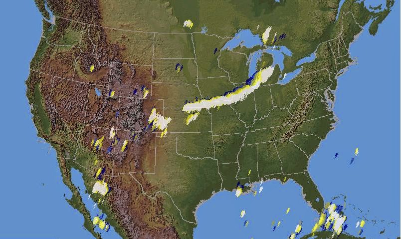 |
| Courtesy: vaisala.com |
Nevertheless, reception reports, often of both beacons, were received from Washington, Oregon, Utah, British Columbia, Alberta and as far east as Saskatoon, SK. It seemed like stronger signals were reported from the east rather than from the south or south-east which is more often the case. I suspect that the lower level of lightning in this direction, rather than enhanced E-W propagation, was the main reason for the nice 'over the Rockies' reception.
Thanks to the following enthusiasts who were kind enough to listen and to report on Saturday night's activities, hopefully I haven't missed anyone:
KK7UV (Steve) MT *
W7SWL (Bob) AZ *
VE6TA (Grant) Alberta
AA7U (Steve) OR
VA5LF (Sean) Saskatchewan
VA7JX (Jack) British Columbia
WY3B (Mike) HI *
W7WKR (Dick) WA
K7WV (Tom) WA
KU7Z (Mark) UT
W7OIL (Dan) WA
G0NSL (Brian) UK *
Colin Newell, British Columbia
* stations reporting no reception
It appears that even under fairly severe conditions (mid-summer QRN), small backyard antenna systems and 100W can propagate well enough for CW contacts on the 630m band. The band is certainly much more prop-friendly than 2200m and quiet winter conditions will be even better. In the meantime I hope to make some crossband contacts with anyone that might like to try that mode.
 “Night of Nights” + VE7 CW Beacons – tonight
As many of you are aware, tonight from 0001Z-0700Z (1701- midnight PDT) is the annual 'Night of Nights' reactivation of many maritime CW MF stations operating near the 630m band. With Canadian amateurs recently getting 472-479KHz operating privileges, VE7BDQ and myself will both be operating CW beacons during the event.
VE7BDQ will transmit on 474.00 KHz while VE7SL will be on 473.00KHz. Both stations will be at the 100W power level.
Reception reports of either station would be gratefully received and confirmed by QSL if requested. Hopefully the usual noisy summer conditions will not detere listener activity.
I have more information on the 'Night of Nights' activity posted in an earlier blog if you are not aware of the event.
 500KHz Lives Again – 2014 Night of Nights
 |
| Courtesy: Maritime Radio Historical Society |
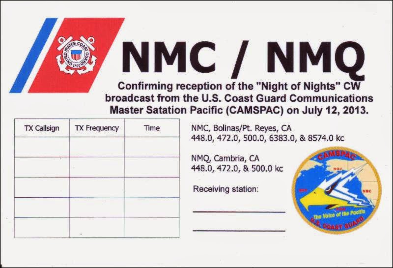
This year's annual Maritime Radio Historical Society's event, to mark the anniversary of the end of maritime CW in 1999, will take place Sunday, July 13, from 0001Z until 0700Z (Saturday, July 12, from 1701 until midnight PDT). This year's event may be historic in itself in that it will likely be the final year for any of the U.S. Coast Guard stations to ever be heard again on CW, as the equipment and wiring for this mode is now being dismantled.
 |
| Courtesy: Maritime Radio Historical Society |
Commercial CW land station transmitters from WLO (Mobile, AL), KLB (Seattle, WA), KFS (San Francisco, CA), KPH (Bolinas, CA) and KSM (Pt. Reyes, CA) should be active near 500KHz as well as on HF.
(late update: due to operator illness, KLB will not be participating)
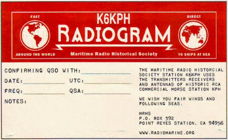
USCG stations NMC (Bolinas/Pt. Reyes), NMQ (Cambria /Pt. Reyes) and NMW (Astoria / Pt. Reyes) will also be transmitting below 500KHz as well as on HF. QSL's confirming reception of CG stations as well as for K6KPH and KSM will be available following the event.
K6KPH, the MRHS's amateur radio station located at the Pt. Reyes, CA site, will also be active on the HF bands during the event.
For a nice historical 'look back', the MRHS has some great stories associated with HF and MF maritime operations. Further details of the event detailing times and exact frequencies are available from MRHS newsletter #45.
Lastly, if you never had the opportunity to listen to '500' back in its heyday then you will surely enjoy this recording made by K2NP in March,1966 and presented with thanks to N1EA. Listening to this 500KHz action reminds me of 20m CW during the annual DX contest! What land stations can you identify in the pileups? Hopefully, when all North American amateurs gain access to the band, it will sound like this once again.


