Posts Tagged ‘TEN-TEC Century 21’
 Making use of Elecraft Mini-module Kits
Connecting the bits and bobs
I have enjoyed building Elecraft Mini-Module kits. Now to put them to use...
 |
| Elecraft Mini-Module Kits |
What to do?
I built the kits as part of my learning adventure and to improve my soldering skills. It's also helped me learn to follow instructions better (my wife says I need to work on learning to follow instructions). But ultimately these modules are intended to be useful, and in my case they work nicely to when operating my old Ten-Tec Century/21.
My Ten Tec Century/21 is a 1970s CW-only, low(ish) power rig originally intended for Novice license holders of the time. It has no RF output meter or SWR meter. It has poor filtering/selectivity compared to modern radios and its analog tuning dial is a bit vague so you generally only know your frequency within 5 kHz.
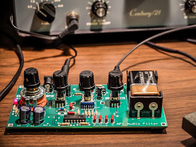
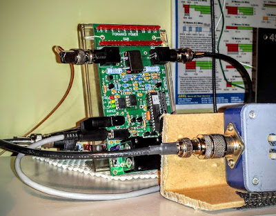
The mini-module kits prove useful. I employ the W1 Wattmeter to determine my power output and SWR; the CP1 directional coupler is used to send a 20db attenuated signal to a frequency counter to determine operating frequency, and the AF1 Audio Filter makes operating near adjacent CW signals more pleasant by providing a narrow audio-band-pass filter. The result signal can be transmitted through a LDG tuner into the BL2 switchable balun connected to my attic Doublet.
Bring out your cables
All these independent modules need to be connected, so tying the bits and bobs together requires a few coax jumpers to route the RF around:
- UHF to BNC from the radio to the W1 Power meter
- BNC to BNC From the W1 Power meter to the CP1 coupler
- BNC to UHF From the CP1 coupler J1 input to switched T1 output to frequency counter
- BNC to UHF From the CP1 coupler J2 output to the tuner
And other cables:
- Serial cable from the W1 Power meter to the computer
- 12v power cables for the W1 and AF1 (unless I want to use 9V batteries)
- Audio cable from the TenTec C21 to the AF1
 |
| AF1 Audio Filter making crowded band operations pleasurable |
 |
| CP1 Directional Coupler sending off 20dB attenuated signal to the frequency counter |
 |
| Frequency Counter fed by the CP1 directional coupler. |
 |
| W1 Power Meter sending its measurement off to the computer |
W1 Power Meter Output to Computer
The W1 has a serial output to a PC for use with the Elecraft W1 software. The software can both configure the meter and display more detail than can be determined from the LEDs. Source code is supplied and the command set is documented so it would be easy to write your own software for this.
The W1 power meter LEDs give you relatively discrete output information for the lower two ranges (0.1w to 1.4w) and (1.5w to 14w). But in the high range (over 14w) the LEDs are only displaying 10 watt intervals. For instance in the high range, when the second LED is lit you don't know if your operating just 20 watts or 29 watts. It won't trip the next LED until it crosses the 10 watt boundary in the high range so it can be useful to look at the measurement on the computer if you are operating QRO. I'm not complaining. I understand that the meter is primarily intended as a QRP meter and for QRP power (less than 15 watts) it offers plenty of information.
Here I brought the TenTec Century/21 up to nearly full input drive (55-60 watts) to see what it could output. The rig probably had a few more watts left in there but I didn't want to push it because I haven't gotten around to replacing some of the out of spec components in the internal power supply. I normally use this radio under 10 watts (I look for about 30 watts input on the drive meter) but I was curious to see what the old girl could do since I had the meter hooked up to the computer display.
| Measuring maximum RF output from the Ten Tec Century/21 |
Nits and Quibbles
My antenna's native SWR at 15m (~21.08MHz) is around 2.5 so it requires tuning (impedance matching). After my LDG auto tuner spends a ridiculous amount of time trying to find a match it settles at 1.7 SWR according to the W1 Wattmeter, while the indication on the Autotuner is that it believes the SWR is 1.5 or better, while the radio on the other side of the W1 meter sees a SWR over 2.5. I only see this behavior on 15m so I think there is some strange impedance reaction occurring in the W1 wattmeter that is changing the reactance on the jumper to the radio. I've tried a few different jumpers, swapping jumpers, etc. But it always presents an abnormally high SWR to the radio at 15m. Now when I transmit into a dummy load I don't see this behavior, so it is some combination of SWR / reactance present at W1 that causes a impedance mismatch downstream toward the radio. I have more investigating to do but for now I am choosing to not use the W1 Wattmeter in-line when operating on 15m.
The CP1 directional coupler is not entirely transparent and raises the SWR by a bit as signal passes through it. You would expect there to be losses according to the -20 db taps (one forward and one reverse). This should work out to about 0.08% loss but I wouldn't expect it to raise the SWR. It adds about 0.1 to your SWR and occurs even if the forward and reverse couplers are switched "off" and shunt their respective loads to the on-board 50 ohm resistors. I'm unsure what accounts for that slight SWR bump but be aware that CP1 contributes some very small losses.
Summary
So the Elecraft Mini-modules are fun to build; and with enough jumper cables, can be combined for experiments and general augmentation of other equipment in your shack. So go out there, build some kits and experiment. It's a rewarding experience.
I'm trying to decide what I'm going to build next.
That's all for now...
So lower your power and raise your expectations
73/72
Richard, N4PBQ
 Get a taste of the RF coming and going
Elecraft CP1 - A tasty RF treat
I had some time this afternoon to assemble another Elecraft mini-module kit. This time it was the Elecraft CP1 directional coupler.
| Elecraft CP1 Kit |
Couple what?
Ah, so if your new to this like me you might be asking what does a coupler do? Well it sorta listens in on the signal going out (forward) and reflected (back) and is able to send an attenuated sample of the signal to other devices. It attenuates the sample by either 20db or 30db depending on how you build the kit.The 20db version is good for signals 25 watts and less so that's the way I built it. It was easy to build but my glue under the second toroid wasn't strong enough and you can see it popped up a bit. Also the Elecraft instructions had one confusing instruction concerning mounting the toroids. The instructions say "... When wound and mounted correctly, the enamel wire will emerge from the top of each core and connect to the top hole at each inductor location". Well when you wind a toroid only one of the wires can "emerge from the top of the core" while the other comes from underneath. This confused me for a minute until I finally just went on with the install. Anyway, if you're a stickler for following instructions that one may cause a moment of pause...
The switches for the two outputs forward, reflected (J3, J4) are in the up position when they are not in use. When the switch(es) are in the up position the 50 ohm 3 watt resistor(s) take the place of the switched off output. Don't disconnect an output and leave the switch in the bottom position. I'm not sure what will happen... maybe nothing, probably a bit of a mismatch on the SWR, or maybe it could be like "Crossing the streams" in Ghostbusters. Your mileage may vary.
My uses for a coupler
My old Ten-Tec Century 21 has an analog VFO dial that gives me a good guess at where I'm at but I use an external frequency counter to give me more information. I had it sorta rigged my frequency counter to sample the signal from RF leaked on the shield but I didn't really know how much power I was sending to the counter so this coupler allows it, as well as other devices, to be safely connected to the transmitted signal.I also plan to use the coupler for IMD tests using a oscilloscope and other projects. It's handy device to have in your collection.
My confusion
I will admit I am still such an idiot when it comes to understanding how this stuff works. After I built it I was testing continuity and saw that input/output (J1, J2) both showed a short from ground to center pin on both BNC connectors. I thought I'd mis-soldered something and spent the next two hours unsoldering components and trying to trace the fault...
There was no fault. The way this thing works is a bit of mystery to me but as best I can tell it simply reverses the phase of the signal coming in one side (J1) and leaving the other (J2) and as far as continuity tests go, EVERYTHING has almost zero impedance. I'm still bewildered but it's AC not DC so my continuity tests don't mean much.
But in the end - It works
I finally just resoldered it, scratched my head and thought I'd give it a try. I connected the coupler between my radio and a dummy load and transmitted a watt and noted that the SWR on the radio was fine. Then I hooked up my frequency counter and it worked like a charm sending an attenuated signal to J3 for the frequency counter.
My MFJ watt meter doesn't seem to be all that accurate but I did a power test with it both in-line and absent. My MFJ watt meter measures 300w / 30w so it isn't very accurate at QRP levels. But I noted a slight difference in power reported when the coupler was in-line. If I had to guess by "Mark-One-Eyeball" I'd say the coupler was stealing about 1/2 watt. Maybe a bit more so that's something to consider. I'll know better once I build my Elecraft watt meter since it's accurate down to a tenth of a watt.
That's all for now
So lower your power and raise your expectations
72/73
Richard, N4PBQ
 Finer than a frog’s hair split twice
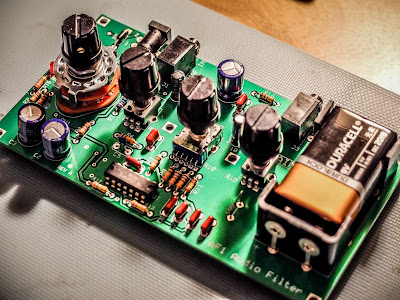
Elecraft AF-1 Audio Filter Kit
I've been working a lot of SKCC CW stations during the holidays and adjacent stations really interfere with my ability to use the vintage Ten-Tec Century/21. Its built-in audio filter is relatively effective if the band isn't too crowded but if I'm working a station and others pop up within a 1kHz on either side I have a real hard time keeping track of which QSO to listen to. I wanted some relief from the relatively porous audio filtering provided by the old girl.
A kit from Elecraft seemed to be the ticket to better signal isolation for my old radio.
 |
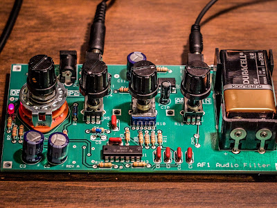
| Elecraft AF-1 Audio Filter Kit |
Building the kit
This kit is about $60 and is pretty easy to build There are a couple of ICs to solder so it will be easier if you have a temperature controlled, fine tipped soldering iron. Santa brought me a nice soldering iron for Christmas so this was my first chance to make some use of it. Everything about the kit is very straightforward and Elecraft has wonderful build instructions along with a well laid out board. Their instructions list components in the order that you will be installing them on the board, left to right and even include the color coding or numbering for resistors and capacitors right there in the instructions so you don't have to keep going back to look up the coding. I've only built one other kit previously and the Elecraft instructions are better.
My only gripe is that this kit has been out for quite some time, but for some reason they shipped me a Version "A" board that required a trace to be cut and a couple of jumpers installed to correct a board error. I would hope that they would ship new versions of the board but apparently you can get an old version. Next time I order a kit from them I may specify that I want the latest revision of the kit.
Performance
The board powered up and worked right as the last of the solder smoke was wafting away. I connected it to the Ten-Tec and tried to find some adjacent station operations to test against but the bands were not terribly busy tonight. I did manage to get a decent audio test on a calling station and created a video to demonstrate the board's capabilities.
Summary
This is the first kit I've built from Elecraft. It was a simple one. The instructions were excellent, the silkscreen layout on the board was straightforward and all the parts were in the bag. The kit does not come with an enclosure so it looks a bit unfinished and the knobs are a bit wobbly on their tall, plastic shafts. That is my only negative concern regarding the finished kit. Putting it in an enclosure would also require the battery holder to be moved to the bottom of the board to clear the shafts exiting the top of an enclosure. Certainly not a big deal but I would be willing to pay an extra $10 for a ready made enclosure because when I've tried to make them they look like junk.
But the bottom line is that if you have an older radio that lacks good filtering or you've built a homebrew radio that you want to be more usable on the air, the Elecraft AF-1 is an excellent addition. I think it is going to serve me well with my vintage radio. Now to find a project box to fit it.
That's all for now
So lower your power and raise your expectations
73/72
Richard, N4PBQ


