Posts Tagged ‘Uncategorized’
 CQRLog CAT control for FT-857D
My last post, I talked about getting Linux setup for my new ham laptop. This is a short post to cover another small step in that process.
Tonight I was working on getting Rig Control working for my FT-857D and CQRLog on Linux. A lot of times, when I read posts like this, or watch youtube videos, people ignore the hardware side and just focus on the software side of things. I am going to try and cover both.
The hardware setup is simple. I am using the programing cable (CT-62B cable) that came with my RT Systems software to connect the CAT port of the FT-857D to a USB port on the laptop. Windows will see this cable a COM port, in my case, COM3 when I booted to Windows.
I found I had to install a couple things in Linux in order to get this working properly. When I intalled CQRLog, hamlib was installed along with it. I also had to install a package called libftdi1. When I look at the output of “dmesg” I see that the CT-62B cable shows up as ttyUSB0 which is the name of the serial port in Linux that I am going to use to communicate with the radio.
In CQRLog I set the following:
- RIG Model = 122 FT-857
- Device = /dev/ttyUSB0
- Serial Speed = 4800 (This is what the radio is set to)
- Check the box for “Run rigctld when program starts”
Everything else on the TRX control setup in CQRLog is set as default and not changed from the installed values.
One last Linux setting, in the /etc/group file, I had to add my user name to the “dialout” group. This can be done with the command usermod from a terminal. In openSUSE which is what I am running, I ran the command “usermod -G dialout k5unx”. I then logged out and back in and started up CRLog. When I opened the TRX control window the frequency matched what was one the radio and when I spun the radio dial, CQRLog changed with it.
More to come as I get up and running with Linux on my ham radio laptop.

New Shack PC – Linux
The last few years, I have been using an old hand me down laptop for my ham radio activities. The old one had little memory, the battery that didn’t last very long, was starting to boot unreliably, even after a Windows reinstall, and a few other issues. So I bought an open box Dell laptop at a discount from a local retailer. It has 8GB of RAM and a 1 TB disk drive and i5 processor. While it’s not a top of the line laptop, it’ll work for what I have intended. Also the screen isn’t the highest resolution but since it’s dedicated to ham radio usage only it won’t be a problem.
My main goal with this project is to use Linux more for my ham radio activities. I now work professionally in the Linux world so I would like to carry that experience into my ham radio hobby. I am setting this up as a dual boot system, keeping Windows 10 that came on it, and then installing OpenSUSE Leap 42.2 as my Linux distribution. I know Ubuntu seems to be the most popular distribution, but I am most familiar with SUSE Enterprise Linux, so OpenSUSE draws on that experience. I run openSUSE 42.2 on my work laptop on a daily basis so I am very familiar with it.
I thought I would post about the steps I am taking to achieve this so if anyone else decides to do something similar, I will have shared what I went through. I will try to follow this up later with posts about using various Linux applications for ham radio like CQRLog, WSJT-X and other things I find useful.
I will use the Windows install for a few things. My old ham radio laptop was running Windows so I can duplicate it’s capabilities if needed. One of those jobs is some Windows software that I bought from RT Systems for programming my radios. I’ll eventually investigate Linux alternatives such as Chirp but that will be low on the priority list.
The first steps I took in the process are:
- Boot into BIOS/uefi and disable Secure Boot. I don’t need this.
- Boot up Windows, create user account, and fully make sure all updates are installed, and any initial setup.
- Make a Windows 10 recovery USB thumb drive. This is built into Windows 10.
- Download the restore image from Dell to restore the laptop if needed.
- Run the Windows Disk Cleanup utility to remove all unneeded files including any previous version of Windows left behind after the updates, and all update related files. I check all the boxes in the cleanup utility including system files.
- Defragment the C: drive. This is needed so I can shrink the C: partition
- Use diskmgmt.msc to shrink the main Windows 10 partition to about 450GB. That will leave about 430GB of free space to use for Linux installation. I had to disable system protection, pagefile and hibernation in order to get the drive to shrink to where I wanted it. These are unmovable files and might hamper the ability to shrink the disk. After shrinking, I reenabled all of those.
- VERY IMPORTANT STEP: Use Clonezilla to make a complete cloned backup of the entire disk drive so I can put Humpty back together if something bad happens or I make a mistake. This will backup all the partitions to a set of files on a USB drive, and allow me to completely restore the drive and partitions. I now have 3 ways to restore the system. Clonezilla backup, restore image I downloaded, and the Windows Recovery thumb drive I created.
- Install Dropbox as I’ll use that to transfer some things from the old laptop to the new one.
BACKUPS are very IMPORTANT as is the ability to UNDO something even if it means a full restore. NOTE: Clonezilla doesn’t backup empty space to the resulting backup is smaller that the drive that’s being cloned.
Now it’s time to install Linux. I made a bootable thumb drive from the openSUSE Leap 42.2 iso. This was done using dd on my work Linux laptop. The website to download openSUSE from is: http://www.opensuse.org. There are two openSUSE distributions. Leap is a point release and Tumbleweed is a rolling release and always at the bleeding edge. If you want something stable then Leap is the way to go. It’s also what I run on my work laptop as my primary OS.
I booted from the Leap thumb drive, and went through a normal install. From the free space I created by shrinking the Windows partition, I made a 4GB swap partition, a 50GB / (root) partition and assigned the rest of the space to /home which is where all my data will reside.
When Linux is installed, it installs the Grub2 bootloader which is able to detect Windows 10 and make it a selection at boot time. When you boot the system, a Grub2 menu will display allowing the choice of which operating system to boot. You can also choose which one boots as default when the grub2 timer expires.
One thing I found . . . When I booted back into Windows, it assigned drive letters to the Linux partitions which is something I did not want. I started up diskmgmt.msc in Windows and removed the drive letter associations from the 3 Linux partitions. That way Windows won’t mount the Linux partitions and possibly cause an issue.
At this point, I have a dual boot system and am ready to go. So far on the Linux side I have installed the following:
- Terminator – A nice terminal program
- cqrlog & mysql – Popular Linux Ham Radio Logging program. I exported my log from HRD (ver 5.24) on the old computer and imported it into cqrlog.
- tqsl – I made a backup of my certificate using tqsl on the old Windows computer and was able to restore it using tqsl on the new Linux installation.
One last thing before moving on. I took another Clonezilla backup of the entire laptop drive. Now I have two Clonezilla backups and could restore either one if I desired.
Just a note on Virtual Machine vs Dual boot. I use VM’s daily on my work laptop and my other personal laptop so I am very accustomed to their use. On my work laptop I run Linux full time with Windows 10 in a virtual machine along with about 10 other Linux VM’s (not all running at once). For the ham laptop I wanted two things. To run Linux as full time as possible for my ham radio hobby, and for the operating system to have direct access to the hardware without the virtualization layer in the middle.
More to come!

A little pre Christmas present
For less than a fiver. CPC shows how far I haven’t come with my minima build. Still the PCB stand looks good. That should make it easier at least.
Available here

Smartlock
The Smartlock is an accessory for my SGC SG-239 HF Smartuner, and other ATUs they make. It can be bought ready made or built.


“I wanted to build a SmartLock to use with my SG-239. After studying the SmartLock schematic, I couldn’t figure out why SGC put in the transistor and zener diode. The ST-TNE input on the SG-239 is just a 1.5K resistor to an open collector transistor to ground. So I eliminated Q1, R3, D1 and C3 on the SGC SmartLock schematic. My final circuit is shown below. I used a DB9S connector to interface with the SGC tuner (I attached a DB9P to the tuner interface wires), and a PowerPole interface for 12VDC. This way I could use a standard DB9 extension cable as necessary for interfacing between the tuner and SmartLock. I used ultra-bright LEDs (3000mcd or so) to provide plenty of visibility.”


SGC Smartlock control


Opportunity
A Maker Faire is a gathering of makers, essentially anyone who builds stuff such robots, electronics, clothes, tools, and equipment. It’s a very heterogeneous culture of people young and old, and includes do-it-youselfers (DIYs), teachers, engineers, scientists, hackers, and geeks. Think of Maker Faires as hamfests for makers. I attended Maker Faire New York City this year, my first Maker Faire. Think of Maker Faire NYC as the Dayton Hamvention of hamfests.

Any drive into The City, as we call it around here, is adventurous. This Faire was located at the New York Hall of Science (NYSCI) in Queens. You couldn’t park anywhere near the event, but there were numerous public mass transit options and two offsite parking areas with shuttle buses. We chose to park at Queens College and take the shuttle in.

The Faire consisted of mostly outdoor and some indoor exhibits, including ones that are part of NYSCI. I can’t do this event justice with the pictures I took, but there’s a pretty good slideshow on the Maker Faire site.

The most popular area, at least judging by the line of people awaiting to enter, was the Radio Shack booth, believe it or not. They had a build your own drone activity that people seemed to be falling all over themselves to get in. If only Radio Shack could get lines like this in their stores.
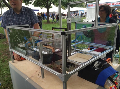
The coolest contraption in my humble opinion was a toasted cheese sandwich machine.
On the Faire map I was pleased to see an area labeled Amateur Radio. I donned my baseball cap embroidered with my callsign, normally reserved for the annual Dayton pilgrimage. The way the map was labeled, I expected to find a whole row of amateur radio stuff. There was one booth with two pop up canopies, manned by perhaps four hams. One side of the booth had a portable rig mounted in a plywood enclosure with some accessory boxes, perhaps a digital station. The other side of the booth had two tables with components and some kids soldering.
I want to be careful not to diminish or criticize the efforts of these amateurs and the organization they represented. After all, these guys made the effort and had an amateur radio booth (which is more than I can say for other organizations). But admittedly I was disappointed. I was really dismayed there weren’t more booths, especially considering the number of amateur radio operators there are in NYC, probably more in a five mile radius than I have in my entire rural county in PA. This is undoubtedly the largest gathering of people on the east coast who are interested in how things work, how to build things, and they’re smart people. Wireless for many makers is just a shield that you buy and plop on an Arduino or a USB dongle you plug into a Raspberry Pi. Amateur radio has so much to offer.
ARRL needs to have an exhibit at this event, in a big way, and not in the fashion they do at Dayton. There needs to be interactive hands-on displays by enthusiastic high energy amateurs. Not hardcore contesters or DXers, but amateurs who build stuff and can talk about practical applications that these makers can relate to and integrate into their existing projects and pursuits. Even CW displays would be interesting for this audience, it just needs to not be presented as a code proficiency course or a rite of passage, but something that is fun. Retro tech intrigues these people. Vacuum tubes would be considered cool by many makers, especially if you had some homebrew rigs built on plywood with filaments lit up and some RF meters dancing around or big old speakers crackling with the sounds of code or sideband coming from a direct conversion receiver. Fox hunts. This crowd would eat that up. Make a crystal radio with six components. There are plenty of high power AM stations in NYC that you can receive on a simple crystal radio. Kids holding Arrow antennas and listening to a satellite passing over. There’s just so much that could be done to showcase amateur radio at this and other Maker Faires, and draw people into the hobby. We’re missing a huge opportunity. Huge.
This article was originally posted on Radio Artisan.
Success!
Great moment this afternoon when the Automatic Loop Controller fired up as it should. Happy days.

When I first fired it up, after loading up the Arduino program, all I could see was a dull green glow on the screen. It wasn’t until I remembered a comment from another builder about adjusting the potentiometer on the PCB that controls the LCD contrast.
It was a great relief that my slow and deliberate build – double checking all component values and joints – paid off. Next step is to build the SWR bridge and connect to the stepper motor on the loop.
NPOTA – First Pile Up
NPOTA as most reading this will know by now, stands for National Park On The Air. It is an ARRl year long event helping the National Park Service celebrate their 100th anniversary. It operates a lot like SOTA in that there are activators and chasers. I was able to participate last Saturday as an activator when I visited some other hams that had setup at the Pea Ridge National Military Park for an activation.

The battle at Pea Ridge was a pivotal Civil War battle that took place March 7-8 1862. The battlefield was spread across 4,300 acres where 26,000 soldiers fought. Today it is still one of the most intact remaining battlefields from the Civil War left in the United States. If you are a history buff and would like more information about the park, you can visit the nps.gov website. Here is the wikipedia page about the battle.
The radio setup consisted of a Yaseu FT-450, a Carolina Windom antenna, and laptop all being powered by a small generator. The team made over 400 contacts for the day. We worked stations fairly constantly most of the day.
I watched the operators for a little while, then jumped in to log for the operator working the radio. After a while they asked me to take the microphone. This was my fist time on the receiving end of a pile up. Someone had spotted us and there were a lot of people all at once trying to contact us. I got flustered and made a lot of mistakes. After a bit, I turned the microphone over to Don, K5DB who was a lot more experienced at working this style of operation. He has been doing NPOTA all year. I went back to login but watching and listening to Don work the pileup, trying to learn. After a while I got back on the mic and tried again. I simply tried to emulate what Don did. I actually was better at it the second time. When I called QRZ or CQ, I would write down 2-4 partial callsigns or even a complete call, as I was able. Then I worked down that small list, calling for the partials. Don got it across to me that I needed to control the pileup. Ask for specific partials, ignore the ones that don’t match that are just trying to barge their way in. I was in charge! I say that not as a control freak but as someone who learned a lot this weekend, working his first pileup.
A few tips for anyone who tackles a NPOTA pileup for the first time. The more experienced ops already know this!
- It’s not a real contest, it’s NPOTA. So relax!
- If you have someone logging for you, you should have paper & pencil for notes, partial callsigns as you operate. I can’t speak to doing this by yourself as I have not done that yet.
- Call the stations you hear, calling back partials as needed.
- Don’t let bully stations barge in when you are calling a specific station. Ignore them.
- Maintain control of the pileup! You are the boss for the moment.
- You can only work one station at a time. You will get to most of them in time.
- You will make mistakes the first time, just deal with it a move on.
- Relax! it’s not a real contest!
I definitely need to get out and operate more in this the of situation.
73 and good luck!


