Posts Tagged ‘variometer’
 A New ‘VE’ on 630m!
 Interest in Canada's newest ham band, 630m, continues to slowly grow. Toby (VE7CNF) in Burnaby, BC, has made his first and second CW contacts on the new band!
 Both myself and John (VE7BDQ) had the pleasure of working Toby on 473.000 CW on Thursday afternoon. Here is Toby's description of his station at present:
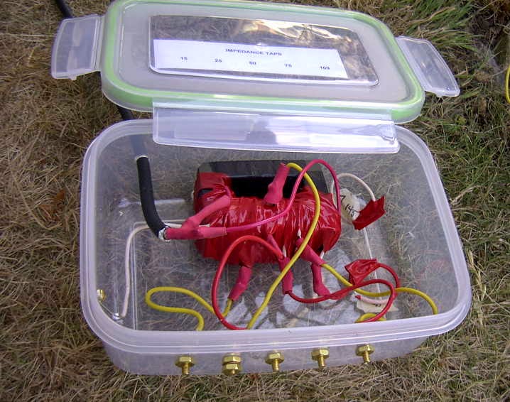
"I have put together a low-power 630m WSPR transmitter here. I have a USB-TG44A signal generator clocking a phasing-type SSB modulator with WSPR audio coming from a laptop. The modulator gives 45db suppression of the carrier and lower sideband. This drives a ZHL-32A 1-watt linear amplifier. I have a matching transformer and loading coil at the base of my 80-meter inverted-L antenna. Wire height is 10m.
John VE7BDQ has weakly received my WSPR signal. Are you able to receive WSPR?
The antenna series resistance is much higher than I expected, probably due to 10 year old antenna wire and only 4 ground radials. Right now the antenna match is poor and efficiency is very low. I may rewind the matching transformer tomorrow and gain a few dB. Maybe soon I’ll have enough signal to complete a 2-way CW QSO with you.
I have attached pictures of the hardware. After I determine the proper configuration I’ll make a more efficient loading coil."
 |
| Courtesy: VE7CNF |
 |
| Courtesy: VE7CNF |
 630m Resources – Part 3
Probably the most-often discussed ham radio topic is that of 'antennas' and with LFers it is no different.
When it comes to antennas used for receiving,
you might be surprised to learn that even small, simple antennas, can be very effective on 630m. Small loops are easy to build and work well as they are often quieter than wire antennas and with preampflication, will usually yield a better signal-to-noise ratio.
The shielded Burhan's loop described here, is a good performer on 630m and below, while a tuned wire loop can be just as effective if resonated to 630m.
Easily built active antennas are also popular and once situated in a quiet spot in your backyard, can work extremely well, considering their size and simplicity. The PAØRDT active antenna is popular worldwide and offers good performance, if properly placed, as shown in this LF bandscan from Japan.
Several of the stations that I recently worked on crossband, from 630m to HF, were using their normal HF dipoles to listen on 630m. Often times a non-resonant antenna, such as an 80m dipole, can give reasonably quiet performance and is worth trying should you just want to listen. Others have used HF dipoles with the feedline shorted and fed as a top-loaded vertical (T), and resonated to 630m against a small radial ground. Try what you presently have and you may be surprised at what you can hear.
Transmitting antennas need not be large to enjoy 630m propagation. For most backyards, an inverted 'L' antenna would probably be the easiest to configure.
If you have a tower, the vertical portion of the 'L' could be hung from a support arm off of the tower, with the horizontal portion as long and as high as possible. If you have some trees to hang wires from, a center-fed 'T' antenna would also be effective.
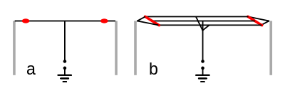 |
| Top-loaded 'T' Antennas. Courtesy: http://en.wikipedia.org/wiki/T-Antenna |
In both of these examples, try and get as much 'vertical' as possible and then work on the top-hat portion. Top-hats with multiple wires will also increase antenna efficiency. An interesting paper by VK2DX, explains the process that he used to build and match a simple inverted 'L'.
 | |
| Courtesy: VK2DX |
As well, JUMA publishes an informative application note on building an 'L' for 630m.
If you don't have room for one of these types of antennas, effective results can also be had with short top-loaded radiators as used at many NDB installations. Try to go as high as you can and make the top-hat as large as possible.
Any of the transmitting antennas described above will require sufficient series inductance (base loading usually) to bring them to resonance as well as some form of variometer to fine-tune exactly. As well, they all require some form of ground system to radiate.
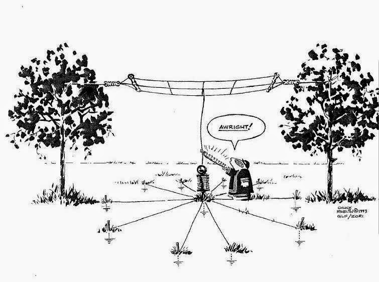
Since most backyards will never be large enough for an efficient ground system on 160m, let alone on 630m, just do the best that you can. You might be surprised at the results achieved with just a simple system of a few buried radials but the more you can lay down, the better. Radials can be effectively hidden beneath the grass with a few days of effort. Some have noted an increase in antenna current when ground rods were driven in at the far end of the radials.
 |
| Courtesy: http://www.auroralchorus.com/ |
This well-written series of articles describing simple antenna systems for the 1750m band is chalk-full of neat ideas and practical information...all applicable to the 630m band.
For an even more in-depth look at practical LF and MF antennas, the ON7YD site is hard to beat...again, all applicable to 630m.
Canada's new 630m band is a wonderful opportunity to build and experiment with all aspects of your station and it's crying out for activity!
It's still not too late to be the first station on 630m from most parts of Canada and the VE7's are waiting to work you!
 630m – Locked & Loaded

Several hours were spent yesterday finishing off the new 630m antenna matching transformer and installing the new loading coil with built-in variometer.
I decided to remove two turns from the bottom half of the coil, lowering the tuning range from 177-330uH to 165-313uH. Still not ideal but slightly more efficient. In reality, any losses from the variometer inefficiency are minuscule compared to the overall ground-system losses and probably unmeasurable. As it stands, the inverted 'L' resonates on 473kHz with 185uH of inductance and ideally the variometer should be operated closer to its total maximum inductance.
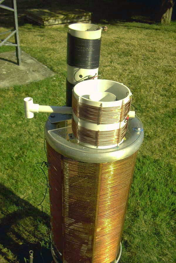
The new coil can be seen mounted on top of the much larger 2200m loading coil, a real monster by comparison. It was removed from one of the local NDB transmitters and saved from going to the scrap yard by an alert technician, who kindly donated it to me when I began operations on 2200m. I can only guess at what this must have cost to purchase when new, as the construction quality is superb.
The new matching transformer is similar to the one that works so well on the 2200m system and wound on two TV flyback ferrite cores.
Once everything was cabled-up, I returned to the shack and plugged the coax into the KØLR antenna meter (VFO) and tuned it to 473kHz. I then went back to the variometer and tuned it while watching the meter through the shack window, looking for the sharp rise in current that would indicate resonance. I swept from one end to the other but saw no change! I eventually realized that I had not attached the antenna downlead to the top of the loading coil...duhh!
Once in place, the sweet-spot was quickly located and I returned to the shack to switch to the transmitter and scope match. For starters I had set the matching transformer to the 50ohm tap but the Scopematch indicated a resistive impedance of about 25 ohms. Moving to the 25 ohm tap resulted in a perfect match as can be seen here with both the current and voltage waveforms in exact phase and amplitude.
The Scopematch truly makes things easy, once you remember to attach the antenna!
The antenna tuning systems for 2200m and 630m are now separate and independent of each other, each with their own coaxial feedline and tuning system but I really wonder if I'll ever be active at all on 2200m again as there just appears to be no real interest amongst Canadian amateurs in our new 'topband'. It's really a shame since so many people worked very hard to obtain 2200m for Canadian amateurs...for me, its been a wonderful learning-ground for building and experimenting, as is 630m.
With the 630m system all ready to go at maximum EIRP, things are all set for the late October 630m Activity Night (hope you will be there). In the meantime, while awaiting new Canadian activity (come on guys!), I'm open for business.
Anyone wishing to try a two-way crossband contact please let me know. Both myself and VE7BDQ would love to work you!
 630m Loading Coil & Variometer Update
I've managed to complete my new 630m loading coil / variometer combination but will need to wait for the completion of my impedance matching transformer before I can test it out on the antenna. From earlier tests on 475kHz, it seems that my inverted 'L' needs about 190uH for resonance on 630m so just a small loading coil was needed. The built in variometer will allow the system to be tuned to resonance easily, without the need for playing with taps. Once I had started to wind the main coil, I decided to put on a few more turns than I had originally planned, reasoning that it would be easier to remove turns if less inductance was needed than it would be to add more turns if I fell short.
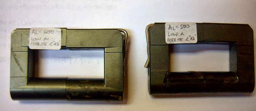
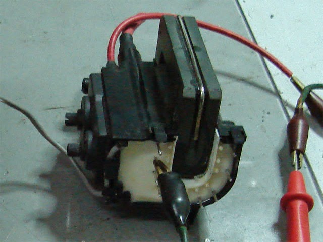
To avoid core saturation at 1kW, my 2200m transformer was wound on two pieces of 'street ferrite', a phrase coined by VE7TIL to describe the abundance of these free flyback cores often to be found in discarded TV's and computer monitors. The ferrite usually has a very high permeability and works well in this application as well as for switching FET amplifier output transformers...and, the price is right!
The challenge is removing the core from its encapsulated shroud without damaging the core. Once you get the hang of it, it is fairly easy to do, but you must work carefully with the brittle ferrite. With the proliferation of LED TV's and monitors, this source of free cores will not be around much longer so grab them while you can ....this ferrite is just too good to throw away!
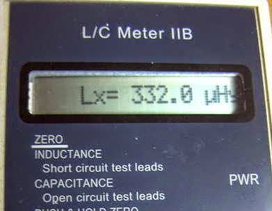
Originally planning for something in the 130-230uH range, the final result produced 177-332uH...certainly more than enough and perhaps a little too much more. I may end up removing a few turns from the main coil as apparently the best variometer efficiency is realised when operated towards the maximum end of inductance, rather than at the low end or when the inner coil is bucking the main coil.
My matching transformer will be similar to the one used on my 2200m system for the past several years. Construction details may be found on the GW4ALG web site. This method of matching, rather than tapping up from the grounded end of the loading coil to find the correct impedance match, is much easier to use and readily allows for changes to be made as the seasons change from winter (wet) to summer (dry).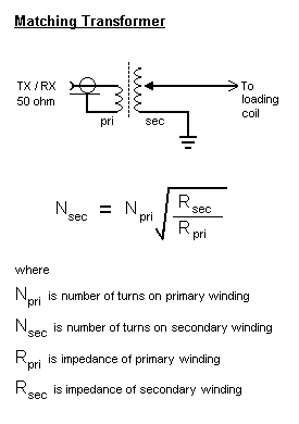 |
| Source: http://www.alg.myzen.co.uk/radio/136/ant_xformer.htm |
 | ||
| Source: http://www.alg.myzen.co.uk/radio/136/ant_xformer.htm |
 |
| Source: http://leoricksimon.blogspot.ca/2007/05/flyback-driver.html |


.jpg)
